diris a40/a41 rs485 â profibus® dp - SOCOMEC Group
diris a40/a41 rs485 â profibus® dp - SOCOMEC Group
diris a40/a41 rs485 â profibus® dp - SOCOMEC Group

You also want an ePaper? Increase the reach of your titles
YUMPU automatically turns print PDFs into web optimized ePapers that Google loves.
<strong>SOCOMEC</strong> GROUP switchiNG PROtEctiON & uPs<br />
DIRIS A40/A41<br />
RS485 – PROFIBUS ® DP<br />
Operating instructions<br />
F GB D I NL E P
2 DIRIS A20 - Réf. : 536 182 A GB<br />
876_786_A_gb.indd 2 3/04/09 10:50:47
GB<br />
contents<br />
PRELIMINARY OPERATIONS 4<br />
GENERAL INFORMATION 4<br />
INSTALLATION 5<br />
PROGRAMMING 6<br />
CONFIGURATION 10<br />
USE OF PROFIBUS ® -DP MODULES 15<br />
MODULE 1 : MAIN MEAsUREMENTs 15<br />
MODULE 2 : ADDITIONAL MEAsUREMENTs 20<br />
MODULE 3 : TROUGh/pOwER CUT/ MEAN pOwER 22<br />
MODULE 4 : OvERvOLTAGE/MEAN vOLTAGE<br />
AND FREqUENCIEs/MAxIMUM IN AND MEAN IN 23<br />
MODULE 5 : CURRENT hARMONICs 24<br />
MODULE 6 : phAsE TO phAsE vOLTAGE 25<br />
MODULE 7 : phAsE TO NEUTRAL vOLTAGE 26<br />
MODULE 8 : INsTANTANEOUs MIN/MAx 27<br />
MODULE 9 : spECIAL FRAME 28<br />
MODULE 11 : LIMITED spECIAL FRAME 36<br />
DIAGNOSTICS 37<br />
TECHNICAL CHARACTERISTICS 39<br />
DIRIS A20 - Réf. : 536 182 A GB<br />
876_786_A_gb.indd 3 3/04/09 10:50:47<br />
3
DIRIs 699 A GB<br />
DIRIS A40/A41 - RS485 - PROFIBUS ® DP<br />
PRElimiNaRy OPERatiONs<br />
For personnel and product safety please read the<br />
contents of these operating instructions carefully<br />
before connecting.<br />
Check the following points as soon as you receive<br />
the Diris A40/A41 package:<br />
• the packing is in good condition,<br />
• the product has not been damaged during transit,<br />
GENERal iNfORmatiON<br />
Functions<br />
This optional module must be connected to the<br />
DIRIS A40/A41 (ref. 4825 0A40, 4825 0A41, 4825 1A40,<br />
4825 1A41). It provides an Rs485 serial link (2 or 3<br />
wires) with pROFIBUs ® Dp protocol for the use of<br />
DIRIS A40/A41 from a PC or PLC.<br />
Recommendations:<br />
You should use a garantieed cable PROFIBUS.<br />
4 DIRIS A20 - Réf. : 536 182 A GB<br />
• the product reference number conforms to your<br />
order,<br />
• the package contains the product,<br />
• a CD-Rom.<br />
General points<br />
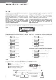
In a standard configuration, an RS485 link allows 1 to 32<br />
DIRIS A40/A41 to be linked to 1 to 32 pieces of equipment<br />
using the PROFIBUS ® -DP protocol. The maximum<br />
communication speed is 1.5 Mbauds over 200 m.<br />
This distance can be increased if the speed is reduced<br />
(standards: EN50170).<br />
NB :<br />
An active termination must be fitted at both ends of<br />
the connection, which can be found either on the<br />
RS485 module (attached by moving the 2 switches<br />
to ON), or directly on the PROFIBUS-DP connector<br />
(D-Sub 9-pin).<br />
876_786_A_gb.indd 4 3/04/09 10:50:47
DIRIS A40/A41 - RS485 - PROFIBUS ® DP<br />
iNstallatiON<br />
cONNEctiON<br />
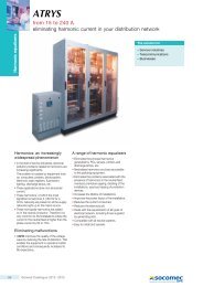
The option modules are installed on the rear panel of the DIRIS A40/A41 in one of the four positions provided.<br />
DIRIs 342 A <br />
DIRIs 469 B <br />
The DIRIS A40/A41 must be switched off<br />
Note :<br />
Correspondence with a HAN BRID connector<br />
+ = B (red)<br />
- = A (green)<br />
DIRIs 469 B<br />
DIRIs 343 A Fix the option modules next to each other<br />
Follow indications when connecting the terminal<br />
switch on voltage supply<br />
Sub D-9<br />
DIRIS A20 - Réf. : 536 182 A GB<br />
876_786_A_gb.indd 5 3/04/09 10:50:51<br />
5<br />
GB
DIRIS A40/A41 - RS485 - PROFIBUS ® DP<br />
PROGRammatiON<br />
6 DIRIS A20 - Réf. : 536 182 A GB<br />
Previous menu<br />
Following menu<br />
876_786_A_gb.indd 6 3/04/09 10:50:52<br />
p.7<br />
p.8<br />
p.9
cOmmuNicatiON addREss<br />
> Example : COM ADR = 7<br />
x 3<br />
x 2<br />
x 1<br />
confirm<br />
DIRIS A40/A41 - RS485 - PROFIBUS ® DP<br />
PROGRammatiON<br />
DIRIS A20 - Réf. : 536 182 A GB<br />
876_786_A_gb.indd 7 3/04/09 10:50:53<br />
7<br />
GB
DIRIS A40/A41 - RS485 - PROFIBUS ® DP<br />
PROGRammatiON<br />
diaGNOstiQuE<br />
> Example : COM DIAG = NO<br />
8 DIRIS A20 - Réf. : 536 182 A GB<br />
x 1<br />
NB :<br />
This function allows switching the diagnosis function<br />
or off. (see p. 37)<br />
x 1 (NO)<br />
x 2 (YES)<br />
x 1<br />
confirm<br />
876_786_A_gb.indd 8 3/04/09 10:50:53
activatiON Of thE PROGRammE via thE PROfiBus mastER<br />
> Example : COM PARA = YES<br />
x 1<br />
Nb :<br />
This function allows activating or deactivation of the<br />
DIRIS programming by the PROFIBUS DP master. If<br />
this function is deactivated please note that in case of<br />
loss of the slave (DIRIS) the master will not send the<br />
GSD file parameters and thus won’t re-programme<br />
the DIRIS A with the factory parameters.<br />
x 1 (YES)<br />
x 2 (NO)<br />
x 1<br />
confirm<br />
DIRIS A40/A41 - RS485 - PROFIBUS ® DP<br />
PROGRammatiON<br />
DIRIS A20 - Réf. : 536 182 A GB<br />
876_786_A_gb.indd 9 3/04/09 10:50:54<br />
9<br />
GB
DIRIS A40/A41 - RS485 - PROFIBUS ® DP<br />
cONfiGuRatiON<br />
The table below gives the configuration of the DIRIS A40/A41 used when starting a PROFIBUS ® -DP cycle.<br />
Name Size<br />
(bytes)<br />
Manufacturer parameter 1<br />
Always equal to zero<br />
Network type 1<br />
0 : 1 BL<br />
1 : 2 BL<br />
2 : 3 BL<br />
3 : 3 NBL<br />
4 : 4 BL<br />
5 : 4 NBL<br />
CT secondary (A) 1<br />
1 : 1 A<br />
5 : 5 A<br />
CT primary (A) 2<br />
voltage input on pT 1<br />
0 : No<br />
1 : Yes<br />
PT primary (V) 4<br />
pT secondary (v) 1<br />
60 : 60 v<br />
100 : 100 v<br />
110 : 110 v<br />
115 : 115 v<br />
120 : 120 v<br />
173 : 173 v<br />
190 : 190 v<br />
synchronisation of I AvG / MAx 1<br />
5 : 5 mn<br />
8 : 8 mn<br />
10 : 10 mn<br />
15 : 15 mn<br />
20 : 20 mn<br />
30 : 30 mn<br />
60 : 60 mn<br />
synchronisation of p / q / s AvG / MAx 1<br />
5 : 5 mn<br />
8 : 8 mn<br />
10 : 10 mn<br />
15 : 15 mn<br />
20 : 20 mn<br />
30 : 30 mn<br />
60 : 60 mn<br />
OUT 1 allocation 1<br />
0 : kwh+<br />
1 : kvarh+<br />
2 : kvAh<br />
3 : kwh-<br />
4 : kvarh-<br />
OUT 1 impulse value (kWh / kvarh / kVAh) 1<br />
0 : 0,1<br />
1 : 1<br />
2 : 10<br />
10 DIRIS A20 - Réf. : 536 182 A GB<br />
876_786_A_gb.indd 10 3/04/09 10:50:55
DIRIS A40/A41 - RS485 - PROFIBUS ® DP<br />
cONfiGuRatiON<br />
Name Size<br />
(bytes)<br />
3 : 100<br />
4 : 1000<br />
5 : 10000<br />
OUT 1 impulse duration (ms) 1<br />
1 : 100<br />
2 : 200<br />
3 : 300<br />
4 : 400<br />
5 : 500<br />
6 : 600<br />
7 : 700<br />
8 : 800<br />
9 : 900<br />
OUT 2 allocation 1<br />
0 : kwh+<br />
1 : kvarh+<br />
2 : kvAh<br />
3 : kwh-<br />
4 : kvarh-<br />
OUT 2 impulse value (kWh / kvarh / kVAh) 1<br />
0 : 0,1<br />
1 : 1<br />
2 : 10<br />
3 : 100<br />
4 : 1000<br />
5 : 10000<br />
OUT 2 impulse duration (ms) 1<br />
1 : 100<br />
2 : 200<br />
3 : 300<br />
4 : 400<br />
5 : 500<br />
6 : 600<br />
7 : 700<br />
8 : 800<br />
9 : 900<br />
Analog output type OUT 1 1<br />
0 : 0 / 20 mA<br />
1 : 4 / 20 mA<br />
2 : Alim<br />
Allocation of analog output OUT 1 1<br />
0 : I1<br />
1 : I2<br />
2 : I3<br />
3 : In<br />
4 : U12<br />
5 : U23<br />
6 : U31<br />
7 : p<br />
8 : q<br />
9 : s<br />
DIRIS A20 - Réf. : 536 182 A GB<br />
876_786_A_gb.indd 11 3/04/09 10:50:55<br />
11<br />
GB
DIRIS A40/A41 - RS485 - PROFIBUS ® DP<br />
cONfiGuRatiON<br />
Name Size<br />
(bytes)<br />
10 : pF<br />
11 : v1<br />
12 : v2<br />
13 : v3<br />
14 : F<br />
Value at 0 or 4 mA from analog output OUT 1 2<br />
Unit at 0 or 4 mA from analog output OUT 1 1<br />
0 : /<br />
1 : k<br />
2 : M<br />
Value at 20 mA from analog output OUT 1 2<br />
Unit at 20 mA from analog output OUT 1 1<br />
0 : /<br />
1 : k<br />
2 : M<br />
Analog output type OUT 2 1<br />
0 : 0 / 20 mA<br />
1 : 4 / 20 mA<br />
2 : Alim<br />
Allocation of analog output OUT 2 1<br />
0 : I1<br />
1 : I2<br />
2 : I3<br />
3 : In<br />
4 : U12<br />
5 : U23<br />
6 : U31<br />
7 : p<br />
8 : q<br />
9 : s<br />
10 : pF<br />
11 : v1<br />
12 : v2<br />
13 : v3<br />
14 : F<br />
Value at 0 or 4 mA from analog output OUT 2 2<br />
Unit at 0 or 4 mA from analog output OUT 2 1<br />
0 : /<br />
1 : k<br />
2 : M<br />
Value at 20 mA from analog output OUT 2 2<br />
Unit at 20 mA from analog output OUT 2 1<br />
0 : /<br />
1 : k<br />
2 : M<br />
Analog output type OUT 3 1<br />
0 : 0 / 20 mA<br />
1 : 4 / 20 mA<br />
2 : supply<br />
12 DIRIS A20 - Réf. : 536 182 A GB<br />
876_786_A_gb.indd 12 3/04/09 10:50:56
DIRIS A40/A41 - RS485 - PROFIBUS ® DP<br />
cONfiGuRatiON<br />
Name Size<br />
(bytes)<br />
Allocation of analog output OUT 3 1<br />
0 : I1<br />
1 : I2<br />
2 : I3<br />
3 : In<br />
4 : U12<br />
5 : U23<br />
6 : U31<br />
7 : p<br />
8 : q<br />
9 : s<br />
10 : pF<br />
11 : v1<br />
12 : v2<br />
13 : v3<br />
14 : F<br />
Value at 0 or 4 mA from analog output OUT 3 2<br />
Unit at 0 or 4 mA from analog output OUT 3 1<br />
0 : /<br />
1 : k<br />
2 : M<br />
Value at 20 mA from analog output OUT 3 2<br />
Unit at 20 mA from analog output OUT 3 1<br />
0 : /<br />
1 : k<br />
2 : M<br />
Analog output type OUT 4 1<br />
0 : 0 / 20 mA<br />
1 : 4 / 20 mA<br />
2 : supply<br />
Allocation of analog output OUT 4 1<br />
0 : I1<br />
1 : I2<br />
2 : I3<br />
3 : In<br />
4 : U12<br />
5 : U23<br />
6 : U31<br />
7 : p<br />
8 : q<br />
9 : s<br />
10 : pF<br />
11 : v1<br />
12 : v2<br />
13 : v3<br />
14 : F<br />
Value at 0 or 4 mA from analog output OUT 4 2<br />
Unit at 0 or 4 mA from analog output OUT 4 1<br />
0 : /<br />
1 : k<br />
2 : M<br />
DIRIS A20 - Réf. : 536 182 A GB<br />
876_786_A_gb.indd 13 3/04/09 10:50:56<br />
13<br />
GB
DIRIS A40/A41 - RS485 - PROFIBUS ® DP<br />
cONfiGuRatiON<br />
Name Size<br />
(bytes)<br />
Value at 20 mA from analog output OUT 4 2<br />
Unit at 20 mA from analog output OUT 4 1<br />
0 : /<br />
1 : k<br />
2 : M<br />
CT In secondary (A) 1<br />
1 : 1 A<br />
5 : 5 A<br />
CT In primary (A) 2<br />
Length: 54 bytes<br />
NB:<br />
All this information is integrated in the GSD file<br />
(User-Prm-Data).<br />
14 DIRIS A20 - Réf. : 536 182 A GB<br />
Check that the parameterisation data are identical to the data programmed<br />
in the device.<br />
When the PROFIBUS ® master loses a slave, it re-injects the parameters from<br />
the GSD file which will re set the factory configuration.<br />
There are two solutions to inhibit this function:<br />
- Deactivate the master’s DIRIS A programming (see also page 9)<br />
- Configure the DIRIS A through the master, then open and close the DIRIS<br />
A programming menu directly by the keypad (code =100).<br />
876_786_A_gb.indd 14 3/04/09 10:50:57
DIRIS A40/A41 - RS485 - PROFIBUS ® DP<br />
usE Of thE PROfiBus ® -dP mOdulEs<br />
The modules contain the inputs (display) and outputs<br />
(configuration).<br />
mOdulE 1: MAIN MEASUREMENTS<br />
This module contains the currents, powers, frequencies,<br />
power factor, positive energies and hour meter.<br />
Output frame<br />
Example:<br />
Modification of relay 1:<br />
• set bit 4 (relay configuration change),<br />
• set bit 0 (relay 1 to 1),<br />
• modify the status byte on relay 1 break (next byte).<br />
Name Size<br />
(bytes)<br />
Change of relay status<br />
if bit on 1, then taken into account, otherwise bit on 0 1<br />
bit 0: Relay 1<br />
bit 1: Relay 2<br />
bit 2: Relay 3 (second option relay 1)<br />
bit 3: Relay 4 (second option relay 2)<br />
bit 4: Change in relay configuration<br />
bit 5: Resetting of one measurement<br />
bit 6: not used<br />
bit 7: not used<br />
Relay 1 on break 1<br />
0: open<br />
1: closed<br />
Relay 2 on break 1<br />
0: open<br />
1: closed<br />
Relay 3 on break 1<br />
0: open<br />
1: closed<br />
Relay 4 on break 1<br />
0: open<br />
1: closed<br />
Allocation OUT 1 1<br />
0: Cde<br />
1: I<br />
2: U<br />
3: p+<br />
4: q+<br />
5: s<br />
6: F<br />
7: pFL<br />
8: Thd 3I<br />
9: Thd 3U<br />
10: In<br />
11: time<br />
12: v<br />
13: Thd In<br />
14: Thd 3v<br />
15: p-<br />
16: q-<br />
17: pFC<br />
Lower threshold OUT 1 2<br />
Lower threshold unit OUT 1 1<br />
0: /<br />
1: k<br />
2: M<br />
Upper threshold OUT 1 2<br />
DIRIS A20 - Réf. : 536 182 A GB<br />
876_786_A_gb.indd 15 3/04/09 10:50:57<br />
15<br />
GB
DIRIS A40/A41 - RS485 - PROFIBUS ® DP<br />
usE Of thE PROfiBus ® -dP mOdulEs<br />
mOdulE 1: MAIN MEASUREMENTS<br />
Output frame<br />
Name Size<br />
(bytes)<br />
Upper threshold unit OUT 1 1<br />
0: /<br />
1: k<br />
2: M<br />
hysteresis 0 to 99 OUT 1 (%) 1<br />
Time delay OUT 1 (s) 2<br />
Allocation OUT 2 1<br />
0: Cde<br />
1: I<br />
2: U<br />
3: p+<br />
4: q+<br />
5: s<br />
6: F<br />
7: pFL<br />
8: Thd 3I<br />
9: Thd 3U<br />
10: In<br />
11: time<br />
12: v<br />
13: Thd In<br />
14: Thd 3v<br />
15: p-<br />
16: q-<br />
17: pFC<br />
Lower threshold OUT 2 2<br />
Lower threshold unit OUT 2 1<br />
0: /<br />
1: k<br />
2: M<br />
Upper threshold OUT 2 2<br />
Upper threshold unit OUT 2 1<br />
0: /<br />
1: k<br />
2: M<br />
hysteresis 0 to 99 OUT 2 (%) 1<br />
Time delay OUT 2 (s) 2<br />
Zero reset 2<br />
bit 0: Max 3I<br />
bit 1: Max P+<br />
bit 2: Max P-<br />
bit 3: Max Q+<br />
bit 4: Max Q-<br />
bit 5: Max S<br />
bit 6: hour meter<br />
bit 7: kwh+<br />
bit 8: kvarh+<br />
bit 9: kvA<br />
bit 10: kwh-<br />
bit 11: kvarh-<br />
bit 12: all the parameters<br />
bit 13: Input 1<br />
bit 14: Input2<br />
bit 15: not used<br />
16 DIRIS A20 - Réf. : 536 182 A GB<br />
876_786_A_gb.indd 16 3/04/09 10:50:58
mOdulE 1: MAIN MEASUREMENTS<br />
Output frame<br />
DIRIS A40/A41 - RS485 - PROFIBUS ® DP<br />
usE Of thE PROfiBus ® -dP mOdulEs<br />
Name Size<br />
(bytes)<br />
Zero reset, supplementary options 2<br />
bit 0: Input 1<br />
bit 1: Input 2<br />
bit 2: Input 3<br />
bit 3: Input 4<br />
bit 4: Not used<br />
bit 5: Not used<br />
bit 6: Min Max I<br />
bit 7: Min Max In<br />
bit 8: Min Max U<br />
bit 9: Min Max Frequency<br />
bit 10: Min Max PF<br />
bit 11: Min Max P<br />
bit 12: Min Max Q<br />
bit 13: Min Max Thd I<br />
bit 14: Min Max Thd In<br />
bit 15: Min Max Thd U<br />
Length: 29 bytes<br />
DIRIS A20 - Réf. : 536 182 A GB<br />
876_786_A_gb.indd 17 3/04/09 10:50:58<br />
17<br />
GB
DIRIS A40/A41 - RS485 - PROFIBUS ® DP<br />
usE Of thE PROfiBus ® -dP mOdulEs<br />
mOdulE 1: MAIN MEASUREMENTS<br />
Frame of inputs not allocated for current and voltage transformation ratios<br />
Name Size<br />
(bytes)<br />
Phase 1 current (mA) 2<br />
Phase 2 current (mA) 2<br />
Phase 3 current (mA) 2<br />
Neutral current (mA) 2<br />
phase to phase voltage U12 (v / 10) 2<br />
phase to phase voltage U23 (v / 10) 2<br />
phase to phase voltage U31 (v / 10) 2<br />
phase to neutral voltage phase 1 (v / 10) 2<br />
phase to neutral voltage phase 2 (v / 10) 2<br />
phase to neutral voltage phase 3 (v / 10) 2<br />
Frequency (hz / 100) 2<br />
∑ Active power + /- (kw / 10) 2<br />
∑ Reactive power + /- (kvar / 10) 2<br />
∑ Apparent power + /- (kva / 10) 2<br />
∑ power factor L / C 2<br />
-: capacitive and +: inductive (0.001)<br />
I1 max (mA) 2<br />
I2 max (mA) 2<br />
I3 max (mA) 2<br />
Maximum value active power + (W) 2<br />
Maximum value active power – (W) 2<br />
Maximum value reactive power + (var) 2<br />
Maximum value reactive power – (var) 2<br />
Maximum apparent power (VA) 2<br />
Active energy + < 10000 (kwh) 2<br />
Active energy + > 10000 (kwh) 2<br />
Reactive energy + < 10000 (kvarh) 2<br />
Reactive energy + > 10000 (kvarh) 2<br />
Apparent energy < 10000 (kvAh) 2<br />
Apparent energy > 10000 (kvAh) 2<br />
System I (mA) 2<br />
System U (V / 10) 2<br />
System V (V / 10) 2<br />
Hour meter < 10000 (H / 100) 2<br />
Hour meter >10000 (H / 100) 2<br />
Length: 68 bytes<br />
18 DIRIS A20 - Réf. : 536 182 A GB<br />
876_786_A_gb.indd 18 3/04/09 10:50:58
Calculation of the values allocated:<br />
The currents must be multiplied by the CT ratio, the voltages<br />
by the PT ratio (in HV) and the powers by the ratio<br />
CT x PT.<br />
Example:<br />
CT = 100 = 20 VT = 20000 = 200<br />
5 100<br />
CT x VT = 20 x 200<br />
= 4000<br />
Powers will be multiplied by 4000 (if there is no VT,<br />
then VT = 1), currents by 20 and voltages by 200.<br />
NB :<br />
I system = I1 + I2 + I3<br />
3<br />
U system = U12 + U21 + U31<br />
3<br />
V system = V1 + V2 + V3<br />
3<br />
Transformation of signed values into unsigned<br />
values<br />
If the currents, voltages or energies are negative, the<br />
following rule must be applied:<br />
• take the opposite bit by bit of the datum<br />
• add 1 to this opposite<br />
Example:<br />
• negative datum - 28864mv<br />
or in binary : 0111 0000 1100 0000<br />
• opposite is equal to : 1000 1111 0011 1111<br />
• opposite + 1 is equal to : 1000 1111 0100 0000<br />
or in decimal 366,72.<br />
DIRIS A40/A41 - RS485 - PROFIBUS ® DP<br />
usE Of thE PROfiBus ® -dP mOdulEs<br />
DIRIS A20 - Réf. : 536 182 A GB<br />
876_786_A_gb.indd 19 3/04/09 10:50:59<br />
19<br />
GB
DIRIS A40/A41 - RS485 - PROFIBUS ® DP<br />
usE Of thE PROfiBus ® -dP mOdulEs<br />
mOdulE 2: SUPPLEMENTARY MEASUREMENTS<br />
This module contains the measurements by phase,<br />
average values, negative energies, impulse meters<br />
(on / off inputs) and statuses (on / off inputs).<br />
The output frame is identical to module 1.<br />
Input frame<br />
Name Size<br />
(bytes)<br />
Active power phase 1 + /- (kw/10) 2<br />
Active power phase 2 + /- (kw/10) 2<br />
Active power phase 3 + /- (kw/10) 2<br />
Reactive power phase 1 + /- (kvar/10) 2<br />
Reactive power phase 2 + /- (kvar/10) 2<br />
Reactive power phase 3 + /- (kvar/10) 2<br />
Apparent power phase 1 (kvA/10) 2<br />
Apparent power phase 2 (kvA/10) 2<br />
Apparent power phase 3 (kvA/10) 2<br />
power factor phase 1 (0.001)<br />
-: capacitive and +: inductive<br />
2<br />
power factor phase 2 (0.001)<br />
-: capacitive and +: inductive<br />
2<br />
power factor phase 3 (0.001)<br />
-: capacitive and +: inductive<br />
2<br />
Average value I1 (mA) 2<br />
Average value I2 (mA) 2<br />
Average value I3 (mA) 2<br />
Average value active power + (w) 2<br />
Average value active power - (w) 2<br />
Average value reactive power + (var) 2<br />
Average value reactive power - (var) 2<br />
Average value apparent power (vA) 2<br />
Active energy - < 10000 (kwh) 2<br />
Active energy - >10000 (kwh) 2<br />
Reactive energy - < 10000 (kvarh) 2<br />
Reactive energy - > 10000 (kvarh) 2<br />
Input pulse meter 1 < 10000 2<br />
Input pulse meter 1 > 10000 2<br />
Input pulse meter 2 < 10000 2<br />
Input pulse meter 2 > 10000 2<br />
Input pulse meter 3 < 10000 2<br />
Input pulse meter 3 > 10000 2<br />
Input pulse meter 4 < 10000 2<br />
Input pulse meter 4 > 10000 2<br />
Status inputs 1, 2, 3, 4. 2<br />
Length: 66 bytes<br />
20 DIRIS A20 - Réf. : 536 182 A GB<br />
876_786_A_gb.indd 20 3/04/09 10:51:00
Calculation of the values allocated:<br />
The currents must be multiplied by the CT ratio, the<br />
voltages by the PT ratio (in HV) and the powers by the<br />
CT x PT ratio.<br />
Example:<br />
CT = 100 = 20 VT = 20000 = 200<br />
5 100<br />
CT x VT = 20 x 200<br />
= 4000<br />
Powers will be multiplied by 4000 (if there is no VT,<br />
then VT = 1), currents by 20 and voltages by 200.<br />
Status of the inputs :<br />
input 1 = bit 0<br />
input 2 = bit 1<br />
input 3 = bit 2<br />
input 4 = bit 4<br />
If active the bit is on 1.<br />
If inactive the bit is on 0.<br />
Transformation of signed values into unsigned<br />
values<br />
If the currents, voltages or energies are negative, the<br />
following rule must be applied:<br />
• take the opposite bit by bit of the datum<br />
• add 1 to this opposite<br />
Example:<br />
• negative datum - 28864mv<br />
or in binary : 0111 0000 1100 0000<br />
• opposite is equal to : 1000 1111 0011 1111<br />
• opposite + 1 is equal to : 1000 1111 0100 0000<br />
or in decimal 366,72 V.<br />
DIRIS A40/A41 - RS485 - PROFIBUS ® DP<br />
usE Of thE PROfiBus ® -dP mOdulEs<br />
DIRIS A20 - Réf. : 536 182 A GB<br />
876_786_A_gb.indd 21 3/04/09 10:51:00<br />
21<br />
GB
DIRIS A40/A41 - RS485 - PROFIBUS ® DP<br />
usE Of thE PROfiBus ® -dP mOdulEs<br />
mOdulE 3: DIPS/INTERRUPTION/TREND POWERS AND FREQUENCY<br />
Name Size<br />
(bytes)<br />
Last voltage dips<br />
Residual phase to phase voltage involved: 0: none, 5: U12, 6: U23, 7: U31 1<br />
value (v/100) 4<br />
Residual phase to neutral voltage involved: 0: none, 22 : V1, 23: V2, 24: V3 1<br />
value (v/100) 4<br />
Length (ms) 4<br />
Month 1<br />
Day 1<br />
Year 1<br />
hour 1<br />
Minute 1<br />
second 1<br />
Last power interruption<br />
Month 1<br />
Day 1<br />
Year 1<br />
hour 1<br />
Minute 1<br />
second 1<br />
Last average power<br />
Last p+ value (kw/10) 2<br />
Last p- value (kw/10) 2<br />
Last q+ value (kvar/10) 2<br />
Last q- value (kvar/10) 2<br />
Last average frequency<br />
Last frequency value (hz/100) 2<br />
Length: 36 bytes<br />
22 DIRIS A20 - Réf. : 536 182 A GB<br />
876_786_A_gb.indd 22 3/04/09 10:51:00
mOdulE 4: SWELL/TREND VOLTAGES/IN MAXIMUM AND AVERAGE<br />
DIRIS A40/A41 - RS485 - PROFIBUS ® DP<br />
usE Of thE PROfiBus ® -dP mOdulEs<br />
Name Size<br />
(bytes)<br />
Last swell<br />
Maximum phase to phase voltage involved: 0: none, 5: U12, 6: U23, 7: U31 1<br />
value (v/100) 4<br />
Maximum phase to neutral voltage involved: 0: none, 22 : V1, 23: V2, 24: V3 1<br />
value (v/100) 4<br />
Length (ms) 4<br />
Month 1<br />
Day 1<br />
Year 1<br />
hour 1<br />
Minute 1<br />
second 1<br />
Average voltage<br />
Last phase to phase voltage value U12 (v/10) 2<br />
Last phase to phase voltage value U23 (v/10) 2<br />
Last phase to phase voltage value U31 (v/10) 2<br />
Last phase to neutral voltage value v1 (v/10) 2<br />
Last phase to neutral voltage value v2 (v/10) 2<br />
Last phase to neutral voltage value v3 (v/10) 2<br />
Average and maximum neutral current<br />
Average In (mA) 2<br />
Average maximum In (mA) 2<br />
Length: 36 bytes<br />
DIRIS A20 - Réf. : 536 182 A GB<br />
876_786_A_gb.indd 23 3/04/09 10:51:01<br />
23<br />
GB
DIRIS A40/A41 - RS485 - PROFIBUS ® DP<br />
usE Of thE PROfiBus ® -dP mOdulEs<br />
mOdulE 5: CURRENT HARMONICS<br />
This module contains the thd Is, the thd INs and the<br />
individual harmonics up to number 15.<br />
The output frame is identical to module 1.<br />
Input frame<br />
Name Size<br />
(bytes)<br />
Thd I1 (0.1 %) 2<br />
Thd I2 (0.1 %) 2<br />
Thd I3 (0.1 %) 2<br />
Thd In (0.1 %) 2<br />
Harmonic I1 row 3 (0.1 %) 2<br />
Harmonic I2 row 3 (0.1 %) 2<br />
Harmonic I3 row 3 (0.1 %) 2<br />
Harmonic In row 3 (0.1 %) 2<br />
Harmonic I1 row 5 (0.1 %) 2<br />
Harmonic I2 row 5 (0.1 %) 2<br />
Harmonic I3 row 5 (0.1 %) 2<br />
Harmonic In row 5 (0.1 %) 2<br />
Harmonic I1 row 7 (0.1 %) 2<br />
Harmonic I2 row 7 (0.1 %) 2<br />
Harmonic I3 row 7 (0.1 %) 2<br />
Harmonic In row 7 (0.1 %) 2<br />
Harmonic I1 row 9 (0.1 %) 2<br />
Harmonic I2 row 9 (0.1 %) 2<br />
Harmonic I3 row 9 (0.1 %) 2<br />
Harmonic In row 9 (0.1 %) 2<br />
Harmonic I1 row 11 (0.1 %) 2<br />
Harmonic I2 row 11 (0.1 %) 2<br />
Harmonic I3 row 11 (0.1 %) 2<br />
Harmonic In row 11 (0.1 %) 2<br />
Harmonic I1 row 13 (0.1 %) 2<br />
Harmonic I2 row 13 (0.1 %) 2<br />
Harmonic I3 row 13 (0.1 %) 2<br />
Harmonic In row 13 (0.1 %) 2<br />
Harmonic I1 row 15 (0.1 %) 2<br />
Harmonic I2 row 15 (0.1 %) 2<br />
Harmonic I3 row 15 (0.1 %) 2<br />
Harmonic In row 15 (0.1 %) 2<br />
Length: 64 bytes<br />
NB:<br />
The individual harmonics are available if the harmonic<br />
module is connected.<br />
24 DIRIS A20 - Réf. : 536 182 A GB<br />
876_786_A_gb.indd 24 3/04/09 10:51:01
mOdulE 6: PHASE TO PHASE VOLTAGE HARMONICS<br />
This module contains the thd 3U and the individual harmonics<br />
up to number 15.<br />
The output frame is identical to module 1.<br />
DIRIS A40/A41 - RS485 - PROFIBUS ® DP<br />
usE Of thE PROfiBus ® -dP mOdulEs<br />
Input frame<br />
Name Size<br />
(bytes)<br />
Thd U12 (0.1 %) 2<br />
Thd U23 (0.1 %) 2<br />
Thd U31 (0.1 %) 2<br />
Harmonic U12 row 3 (0.1 %) 2<br />
Harmonic U23 row 3 (0.1 %) 2<br />
Harmonic U31 row 3 (0.1 %) 2<br />
Harmonic U12 row 5 (0.1 %) 2<br />
Harmonic U23 row 5 (0.1 %) 2<br />
Harmonic U31 row 5 (0.1 %) 2<br />
Harmonic U12 row 7 (0.1 %) 2<br />
Harmonic U23 row 7 (0.1 %) 2<br />
Harmonic U31 row 7 (0.1 %) 2<br />
Harmonic U12 row 9 (0.1 %) 2<br />
Harmonic U23 row 9 (0.1 %) 2<br />
Harmonic U31 row 9 (0.1 %) 2<br />
Harmonic U12 row 11 (0.1 %) 2<br />
Harmonic U23 row 11 (0.1 %) 2<br />
Harmonic U31 row 11 (0.1 %) 2<br />
Harmonic U12 row 13 (0.1 %) 2<br />
Harmonic U23 row 13 (0.1 %) 2<br />
Harmonic U31 row 13 (0.1 %) 2<br />
Harmonic U12 row 15 (0.1 %) 2<br />
Harmonic U23 row 15 (0.1 %) 2<br />
Harmonic U31 row 15 (0.1 %) 2<br />
Length: 48 bytes<br />
NB:<br />
The individual harmonics are available if the harmonic<br />
module is connected.<br />
DIRIS A20 - Réf. : 536 182 A GB<br />
876_786_A_gb.indd 25 3/04/09 10:51:02<br />
25<br />
GB
DIRIS A40/A41 - RS485 - PROFIBUS ® DP<br />
usE Of thE PROfiBus ® -dP mOdulEs<br />
mOdulE 7: PHASE TO NEUTRAL VOLTAGE HARMONICS<br />
This module contains the thd 3V and the individual harmonics<br />
up to number 15.<br />
The output frame is identical to module 1.<br />
Input frame<br />
Name Size<br />
(bytes)<br />
Thd v1 (0.1 %) 2<br />
Thd v2 (0.1 %) 2<br />
Thd v3 (0.1 %) 2<br />
Harmonic V1 row 3 (0.1 %) 2<br />
Harmonic V2 row 3 (0.1 %) 2<br />
Harmonic V3 row 3 (0.1 %) 2<br />
Harmonic V1 row 5 (0.1 %) 2<br />
Harmonic V2 row 5 (0.1 %) 2<br />
Harmonic V3 row 5 (0.1 %) 2<br />
Harmonic V1 row 7 (0.1 %) 2<br />
Harmonic V2 row 7 (0.1 %) 2<br />
Harmonic V3 row 7 (0.1 %) 2<br />
Harmonic V1 row 9 (0.1 %) 2<br />
Harmonic V2 row 9 (0.1 %) 2<br />
Harmonic V3 row 9 (0.1 %) 2<br />
Harmonic V1 row 11 (0.1 %) 2<br />
Harmonic V2 row 11 (0.1 %) 2<br />
Harmonic V3 row 11 (0.1 %) 2<br />
Harmonic V1 row 13 (0.1 %) 2<br />
Harmonic V2 row 13 (0.1 %) 2<br />
Harmonic V3 row 13 (0.1 %) 2<br />
Harmonic V1 row 15 (0.1 %) 2<br />
Harmonic V2 row 15 (0.1 %) 2<br />
Harmonic V3 row 15 (0.1 %) 2<br />
Length: 48 bytes<br />
NB:<br />
The individual harmonics are available if the harmonic<br />
module is connected.<br />
26 DIRIS A20 - Réf. : 536 182 A GB<br />
876_786_A_gb.indd 26 3/04/09 10:51:02
mOdulE 8: MIN / MAX INSTANTS<br />
This module contains the storage of the minimum and<br />
maximum values (if the 2 input / 2 output module is<br />
installed).<br />
The output frame is identical to module 1.<br />
DIRIS A40/A41 - RS485 - PROFIBUS ® DP<br />
usE Of thE PROfiBus ® -dP mOdulEs<br />
Input frame<br />
Name Size<br />
(bytes)<br />
Min. current (mA) 2<br />
Min. neutral current (mA) 2<br />
Min. phase to phase voltage (v/10) 2<br />
Min. frequency (hz/100) 2<br />
Min. power factor (0.001) 2<br />
Min. active power (w) 2<br />
Min. reactive power (var) 2<br />
Thd I min (0.1 %) 2<br />
Thd In min (0.1 %) 2<br />
Thd U min (0.1 %) 2<br />
Max. current (mA) 2<br />
Max. neutral current (mA) 2<br />
Max. phase to phase voltage (V/10) 2<br />
Max. frequency (Hz/100) 2<br />
Max. power factor (0.001) 2<br />
Max. active power (W) 2<br />
Max. reactive power (var) 2<br />
Thd I max (0.1 %) 2<br />
Thd In max (0.1 %) 2<br />
Thd U max (0.1 %) 2<br />
Length: 48 bytes<br />
DIRIS A20 - Réf. : 536 182 A GB<br />
876_786_A_gb.indd 27 3/04/09 10:51:03<br />
27<br />
GB
DIRIS A40/A41 - RS485 - PROFIBUS ® DP<br />
usE Of thE PROfiBus ® -dP mOdulEs<br />
mOdulE 9: SPECIAL FRAME<br />
This module allows the creation of a personalised module.<br />
Input frame<br />
If bit 7 is on 0, then the output frame is a normal frame<br />
Name Size<br />
(bytes)<br />
Change of relay status<br />
if bit on 1, then taken into account, otherwise bit on 0 1<br />
bit 0: Relay 1<br />
bit 1: Relay 2<br />
bit 2: Relay 3 (second option relay 1)<br />
bit 3: Relay 4 (second option relay 1)<br />
bit 4: change in relay configuration<br />
bit 5: resetting of one measurement<br />
bit 6: not used<br />
bit 7: 0 -> configuration frame<br />
Relay 1 on break 1<br />
0: open<br />
1: closed<br />
Relay 2 on break 1<br />
0: open<br />
1: closed<br />
Relay 3 on break 1<br />
0: open<br />
1: closed<br />
Relay 4 on break 1<br />
0: open<br />
1: closed<br />
Allocation OUT 1 1<br />
0: Command<br />
1: I<br />
2: U<br />
3: p+<br />
4: q+<br />
5: s<br />
6: F<br />
7: pFL<br />
8: Thd 3I<br />
9: Thd 3U<br />
10: In<br />
11: time<br />
12: v<br />
13: Thd In<br />
14: Thd 3v<br />
15: p-<br />
16: q-<br />
17: pFC<br />
Lower threshold OUT 1 2<br />
Lower threshold unit OUT 1 1<br />
0: /<br />
1: k<br />
2: M<br />
Upper threshold OUT 1 2<br />
28 DIRIS A20 - Réf. : 536 182 A GB<br />
Example:<br />
Modification of relay 1 :<br />
• set bit 4 (relay configuration<br />
change),<br />
• set bit 0 (relais 1 à 1),<br />
• modify the status byte on relay 1<br />
break (next byte).<br />
876_786_A_gb.indd 28 3/04/09 10:51:03
mOdulE 9: SPECIAL FRAME<br />
Input frame<br />
DIRIS A40/A41 - RS485 - PROFIBUS ® DP<br />
usE Of thE PROfiBus ® -dP mOdulEs<br />
Name Size<br />
(bytes)<br />
Upper threshold unit OUT 1 1<br />
0: /<br />
1: k<br />
2: M<br />
hysteresis 0 to 99 OUT 1 (%) 1<br />
Time delay OUT 1 (s) 2<br />
Allocation OUT 2: – 1<br />
0: Cde<br />
1: I<br />
2: U<br />
3: p+<br />
4: q+<br />
5: s<br />
6: F<br />
7: pFL<br />
8: Thd 3I<br />
9: Thd 3U<br />
10: In<br />
11: time<br />
12: v<br />
13: Thd In<br />
14: Thd 3v<br />
15: p-<br />
16: q-<br />
17: pFC<br />
Lower threshold OUT 2 2<br />
Lower threshold unit OUT 2 1<br />
0: /<br />
1: k<br />
2: M<br />
Upper threshold OUT 2 2<br />
Upper threshold unit OUT 2 1<br />
0: /<br />
1: k<br />
2: M<br />
hysteresis 0 to 99 OUT 2 (%) 1<br />
Time delay OUT 2 (s) 2<br />
Zero reset 2<br />
bit 0: Max 3I<br />
bit 1: Max P+<br />
bit 2: Max P-<br />
bit 3: Max Q+<br />
bit 4: Max Q-<br />
bit 5: Max S<br />
bit 6: hour meter<br />
bit 7: kwh+<br />
bit 8: kvarh+<br />
bit 9: kvA<br />
bit 10: kwh-<br />
bit 11: kvarh-<br />
bit 12: all the parameters<br />
bit 13: Input 1<br />
DIRIS A20 - Réf. : 536 182 A GB<br />
876_786_A_gb.indd 29 3/04/09 10:51:04<br />
29<br />
GB
DIRIS A40/A41 - RS485 - PROFIBUS ® DP<br />
usE Of thE PROfiBus ® -dP mOdulEs<br />
mOdulE 9: SPECIAL FRAME<br />
Input frame<br />
Name Size<br />
(bytes)<br />
bit 14: Input2<br />
bit 15: not used<br />
Zero reset, supplementary options 2<br />
bit 0: Input 1<br />
bit 1: Input 2<br />
bit 2: Input 3<br />
bit 3: Input 4<br />
bit 4: Input 5<br />
bit 5: Input 6<br />
bit 6: Min Max I<br />
bit 7: Min Max In<br />
bit 8: Min Max U<br />
bit 9: Min Max Frequency<br />
bit 10: Min Max PF<br />
bit 11: Min Max P<br />
bit 12: Min Max Q<br />
bit 13: Min Max Thd I<br />
bit 14: Min Max Thd In<br />
bit 15: Min Max Thd U<br />
Not used 4<br />
Length: 33 bytes<br />
If the bit is on 1, then the output frame is as follows<br />
Name Size<br />
(bytes)<br />
Frame number<br />
bit 0-6: frame number<br />
bit 7: 1 -> address frame<br />
1<br />
Address of value 1 2<br />
Address of value 2 2<br />
Address of value 3 2<br />
Address of value 4 2<br />
Address of value 5 2<br />
Address of value 6 2<br />
Address of value 7 2<br />
Address of value 8 2<br />
Address of value 9 2<br />
Address of value 10 2<br />
Address of value 11 2<br />
Address of value 12 2<br />
Address of value 13 2<br />
Address of value 14 2<br />
Address of value 15 2<br />
Address of value 16 2<br />
NB:<br />
The frame number is an identification number. It is<br />
used to check if the answer coming from the slave<br />
device corresponds to the PLC’s request.<br />
The list of values is available p. 31 to 35.<br />
30 DIRIS A20 - Réf. : 536 182 A GB<br />
876_786_A_gb.indd 30 3/04/09 10:51:04
mOdulE 9: SPECIAL FRAME<br />
List of values<br />
DIRIS A40/A41 - RS485 - PROFIBUS ® DP<br />
usE Of thE PROfiBus ® -dP mOdulEs<br />
Name Decimal Hexa.<br />
address address<br />
Phase 1 current (mA) 0 0000<br />
Phase 2 current (mA) 1 0001<br />
Phase 3 current (mA) 2 0002<br />
Neutral current (mA) 3 0003<br />
phase to phase voltage U12 (v/10) 4 0004<br />
phase to phase voltage U23 (v/10) 5 0005<br />
phase to phase voltage U31 (v/10) 6 0006<br />
phase to neutral voltage phase 1 (v/10) 7 0007<br />
phase to neutral voltage phase 2 (v/10) 8 0008<br />
phase to neutral voltage phase 3 (v/10) 9 0009<br />
Frequency (hz/100) 10 000A<br />
Active power (w) 11 000B<br />
Reactive power (var) 12 000C<br />
Apparent power (vA) 13 000D<br />
power factor L / C (0.001) 14 000E<br />
Max. value I1 (mA) 15 000F<br />
Max. value I2 (mA) 16 0010<br />
Max. value I3 (mA) 17 0011<br />
Maximum value active power + (W) 18 0012<br />
Maximum value active power - (W) 19 0013<br />
Maximum value reactive power + (var) 20 0014<br />
Maximum value reactive power - (var) 21 0015<br />
Maximum value apparent power (VA) 22 0016<br />
Active energy + < 10000 (kwh) 23 0017<br />
Active energy + > 10000 (kwh) 24 0018<br />
Reactive energy + < 10000 (kvarh) 25 0019<br />
Reactive energy + > 10000 (kvarh) 26 001A<br />
Apparent energy < 10000 (kvAh) 27 001B<br />
Apparent energy > 10000 (kvAh) 28 001C<br />
Active power phase 1 (w) 29 001D<br />
Active power phase 2 (w) 30 001E<br />
Active power phase 3 (w) 31 001F<br />
Reactive power phase 1 (var) 32 0020<br />
Reactive power phase 2 (var) 33 0021<br />
Reactive power phase 3 (var) 34 0022<br />
Apparent power phase 1 (vA) 35 0023<br />
Apparent power phase 2 (vA) 36 0024<br />
Apparent power phase 3 (vA) 37 0025<br />
power factor phase 1 (0.001) 38 0026<br />
power factor phase 2 (0.001) 39 0027<br />
power factor phase 3 (0.001) 40 0028<br />
Average value I1 (mA) 41 0029<br />
Average value I2 (mA) 42 002A<br />
Average value I3 (mA) 43 002B<br />
Average value active power + (w) 44 002C<br />
Average value active power - (w) 45 002D<br />
Average value reactive power + (var) 46 002E<br />
Average value reactive power - (var) 47 002F<br />
Average value Apparent power (vA) 48 0030<br />
Active energy - < 10000 49 0031<br />
Active energy - >10000 50 0032<br />
DIRIS A20 - Réf. : 536 182 A GB<br />
876_786_A_gb.indd 31 3/04/09 10:51:05<br />
31<br />
GB
DIRIS A40/A41 - RS485 - PROFIBUS ® DP<br />
usE Of thE PROfiBus ® -dP mOdulEs<br />
mOdulE 9: SPECIAL FRAME<br />
List of values<br />
Name Decimal Hexa.<br />
address address<br />
Reactive energy - < 10000 51 0033<br />
Reactive energy - > 10000 52 0034<br />
Input pulse meter 1 < 10000 53 0035<br />
Input pulse meter 1 > 10000 54 0036<br />
Input pulse meter 2 < 10000 55 0037<br />
Input pulse meter 2 > 10000 56 0038<br />
Input pulse meter 3 < 10000 57 0039<br />
Input pulse meter 3 > 10000 58 003A<br />
Input pulse meter 4 < 10000 59 003B<br />
Input pulse meter 4 > 10000 60 003C<br />
status inputs 1 2 3 4 61 003D<br />
Thd I1 62 003E<br />
Thd I2 63 003F<br />
Thd I3 64 0040<br />
Thd In 65 0041<br />
Harmonic I1 row 3 66 0042<br />
Harmonic I2 row 3 67 0043<br />
Harmonic I3 row 3 68 0044<br />
Harmonic IN row 3 69 0045<br />
Harmonic I1 row 5 70 0046<br />
Harmonic I2 row 5 71 0047<br />
Harmonic I3 row 5 72 0048<br />
Harmonic IN row 5 73 0049<br />
Harmonic I1 row 7 74 004A<br />
Harmonic I2 row 7 75 004B<br />
Harmonic I3 row 7 76 004C<br />
Harmonic IN row 7 77 004D<br />
Harmonic I1 row 9 78 004E<br />
Harmonic I2 row 9 79 004F<br />
Harmonic I3 row 9 80 0050<br />
Harmonic IN row 9 81 0051<br />
Harmonic I1 row 11 82 0052<br />
Harmonic I2 row 11 83 0053<br />
Harmonic I3 row 11 84 0054<br />
Harmonic IN row 11 85 0055<br />
Harmonic I1 row 13 86 0056<br />
Harmonic I2 row 13 87 0057<br />
Harmonic I3 row 13 88 0058<br />
Harmonic IN row 13 89 0059<br />
Harmonic I1 row 15 90 005A<br />
Harmonic I2 row 15 91 005B<br />
Harmonic I3 row 15 92 005C<br />
Harmonic IN row 15 93 005D<br />
Thd U12 94 005E<br />
Thd U23 95 005F<br />
Thd U31 96 0060<br />
Harmonic U12 row 3 97 0061<br />
Harmonic U23 row 3 98 0062<br />
Harmonic U31 row 3 99 0063<br />
Harmonic U12 row 5 100 0064<br />
Harmonic U23 row 5 101 0065<br />
32 DIRIS A20 - Réf. : 536 182 A GB<br />
876_786_A_gb.indd 32 3/04/09 10:51:05
mOdulE 9: SPECIAL FRAME<br />
List of values<br />
DIRIS A40/A41 - RS485 - PROFIBUS ® DP<br />
usE Of thE PROfiBus ® -dP mOdulEs<br />
Name Decimal Hexa.<br />
address address<br />
Harmonic U31 row 5 102 0066<br />
Harmonic U12 row 7 103 0067<br />
Harmonic U23 row 7 104 0068<br />
Harmonic U31 row 7 105 0069<br />
Harmonic U12 row 9 106 006A<br />
Harmonic U23 row 9 107 006B<br />
Harmonic U31 row 9 108 006C<br />
Harmonic U12 row 11 109 006D<br />
Harmonic U23 row 11 110 006E<br />
Harmonic U31 row 11 111 006F<br />
Harmonic U12 row 13 112 0070<br />
Harmonic U23 row 13 113 0071<br />
Harmonic U31 row 13 114 0072<br />
Harmonic U12 row 15 115 0073<br />
Harmonic U23 row 15 116 0074<br />
Harmonic U31 row 15 117 0075<br />
Thd v1 118 0076<br />
Thd v2 119 0077<br />
Thd v3 120 0078<br />
Harmonic V1 row 3 121 0079<br />
Harmonic V2 row 3 122 007A<br />
Harmonic V3 row 3 123 007B<br />
Harmonic V1 row 5 124 007C<br />
Harmonic V2 row 5 125 007D<br />
Harmonic V3 row 5 126 007E<br />
Harmonic V1 row 7 127 007F<br />
Harmonic V2 row 7 128 0080<br />
Harmonic V3 row 7 129 0081<br />
Harmonic V1 row 9 130 0082<br />
Harmonic V2 row 9 131 0083<br />
Harmonic V3 row 9 132 0084<br />
Harmonic V1 row 11 133 0085<br />
Harmonic V2 row 11 134 0086<br />
Harmonic V3 row 11 135 0087<br />
Harmonic V1 row 13 136 0088<br />
Harmonic V2 row 13 137 0089<br />
Harmonic V3 row 13 138 008A<br />
Harmonic V1 row 15 139 008B<br />
Harmonic V2 row 15 140 008C<br />
Harmonic V3 row 15 141 008D<br />
I System 142 008E<br />
U System 143 008F<br />
V System 144 0090<br />
Hour meter < 10000 145 0091<br />
Hour meter > 10000 146 0092<br />
DIRIS A20 - Réf. : 536 182 A GB<br />
876_786_A_gb.indd 33 3/04/09 10:51:06<br />
33<br />
GB
DIRIS A40/A41 - RS485 - PROFIBUS ® DP<br />
usE Of thE PROfiBus ® -dP mOdulEs<br />
mOdulE 9: SPECIAL FRAME<br />
Name Decimal Hexa.<br />
address address<br />
Last voltage dips<br />
Residual phase to phase involved:<br />
0: none,<br />
5: U12<br />
6: U23<br />
7: U31 4096 1000<br />
Msb value (v/100) 4097 1001<br />
lsb value (v/100) 4098 1002<br />
Residual phase to neutral involved 4099 1003<br />
0: none<br />
22 : v1<br />
23: v2<br />
24: v3<br />
Msb value (v/100) 4100 1004<br />
lsb value (v/100) 4101 1005<br />
Msb length (ms) 4102 1006<br />
lsb length (ms) 4103 1007<br />
Day 4104 1008<br />
Month 4105 1009<br />
Year 4106 100A<br />
hour 4107 100B<br />
Minute 4108 100C<br />
second 4109 100D<br />
Last power interruption<br />
Day 4110 100E<br />
Month 4111 100F<br />
Year 4112 1010<br />
hour 4113 1011<br />
Minute 4114 1012<br />
second 4115 1013<br />
Last average power<br />
Last p+ value (w) 4116 1014<br />
Last p- value (w) 4117 1015<br />
Last q+ value (var) 4118 1016<br />
Last q- value (var) 4119 1017<br />
Average frequency<br />
Last frequency value (hz/100) 4120 1018<br />
Last swell<br />
Maximum phase to phase involved 4121 1019<br />
0: none<br />
5: U12<br />
6: U23<br />
7: U31<br />
lsb value (v/100) 4122 101A<br />
Msb value (v/100) 4123 101B<br />
Maximum phase to neutral involved 4124 101C<br />
0: none<br />
22 : v1<br />
23: v2<br />
24: v3<br />
34 DIRIS A20 - Réf. : 536 182 A GB<br />
876_786_A_gb.indd 34 3/04/09 10:51:06
mOdulE 9: SPECIAL FRAME<br />
DIRIS A40/A41 - RS485 - PROFIBUS ® DP<br />
usE Of thE PROfiBus ® -dP mOdulEs<br />
Name Decimal Hexa.<br />
address address<br />
lsb value (v/100) 4125 101D<br />
Msb value (v/100) 4126 101E<br />
Msb length (ms) 4127 101F<br />
lsb length (ms) 4128 1020<br />
Month 4129 1021<br />
Day 4130 1022<br />
Year 4131 1023<br />
hour 4132 1024<br />
Minute 4133 1025<br />
second 4134 1026<br />
Average voltage<br />
Last value U12 (v/10) 4135 1027<br />
Last value U23 (v/10) 4136 1028<br />
Last value U31 (v/10) 4137 1029<br />
Last value U1 (v/10) 4138 102A<br />
Last value U2 (v/10) 4139 102B<br />
Last value U3 (v/10) 4140 102C<br />
New values available<br />
Average In (mA) 4141 102D<br />
Average maximum In (mA) 4142 102E<br />
Note:<br />
msb: most significant byte.<br />
lsb: least significant byte.<br />
Input frame<br />
Name Size<br />
(bytes)<br />
Frame number 1<br />
value 1 2<br />
value 2 2<br />
value 3 2<br />
value 4 2<br />
value 5 2<br />
value 6 2<br />
value 7 2<br />
value 8 2<br />
value 9 2<br />
value 10 2<br />
value 11 2<br />
value 12 2<br />
value 13 2<br />
value 14 2<br />
value 15 2<br />
value 16<br />
Length: 33 bytes<br />
2<br />
DIRIS A20 - Réf. : 536 182 A GB<br />
876_786_A_gb.indd 35 3/04/09 10:51:07<br />
35<br />
GB
DIRIS A40/A41 - RS485 - PROFIBUS ® DP<br />
usE Of thE PROfiBus ® -dP mOdulEs<br />
mOdulE 10 : RESERVED FOR MANUFACTURER<br />
mOdulE 11 : SIzE LIMITED SPECIAL FRAME<br />
This module allows the creation of a personalised<br />
module of 4 values.<br />
Output frame<br />
Name Size<br />
(bytes)<br />
Frame number 1<br />
Address of value 1 2<br />
Address of value 2 2<br />
Address of value 3 2<br />
Address of value 4 2<br />
Length: 9 bytes<br />
NB:<br />
The frame number is an identification number. It is<br />
used to check if the answer coming from the slave<br />
device corresponds to the PLC’s request.<br />
The list of values is available p. 31 to 35 (module 9).<br />
Input frame<br />
Name Size<br />
(bytes)<br />
Frame number 1<br />
value 1 2<br />
value 2 2<br />
value 3 2<br />
value 4 2<br />
Length: 9 bytes<br />
36 DIRIS A20 - Réf. : 536 182 A GB<br />
876_786_A_gb.indd 36 3/04/09 10:51:07
DIRIS A40/A41 - RS485 - PROFIBUS ® DP<br />
diaGNOstics<br />
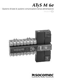
These contain an indication of the presence of<br />
DIRIS A40/A41 option modules, the serial number, the<br />
DIRIS A40/A41 product code and the presence of an<br />
alarm or an excess.<br />
Name Size<br />
(bytes)<br />
Option present on slot 1 1<br />
0: Rs485<br />
1: Metering<br />
3: Harmonics<br />
F0: In<br />
20: 2 In / 2 out<br />
30: 2 0 / 4 - 20 mA<br />
50: pROFIBUs ® -Dp<br />
Option present on slot 2 1<br />
0: Rs485<br />
1: Metering<br />
3: Harmonics<br />
F0: In<br />
20: 2 In / 2 out<br />
30: 2 0 / 4 - 20 mA<br />
50: pROFIBUs ® -Dp<br />
Option present on slot 3 1<br />
0: Rs485<br />
1: Metering<br />
3: Harmonics<br />
F0: In<br />
20: 2 In / 2 out<br />
30: 2 0 / 4 - 20 mA<br />
50: pROFIBUs ® -Dp<br />
Option present on slot 4 1<br />
0: Rs485<br />
1: Metering<br />
3: Harmonics<br />
F0: In<br />
20: 2 In / 2 out<br />
30: 2 0 / 4 - 20 mA<br />
50: pROFIBUs ® -Dp<br />
DIRIs 475 A<br />
DIRIS A20 - Réf. : 536 182 A GB<br />
876_786_A_gb.indd 37 3/04/09 10:51:07<br />
Slot<br />
1<br />
Slot<br />
2<br />
Slot<br />
3<br />
Slot<br />
4<br />
37<br />
GB
DIRIS A40/A41 - RS485 - PROFIBUS ® DP<br />
diaGNOstics<br />
Name Size<br />
(bytes)<br />
Serial number 4<br />
product code 1<br />
Alarms 4<br />
bit 0: Alarm I<br />
bit 1: Alarm In<br />
bit 2: Alarm U<br />
bit 3: Alarm V<br />
bit 4: Alarm P+<br />
bit 5: Alarm Q+<br />
bit 6: Alarm S<br />
bit 7: Alarm F<br />
bit 8: Alarm PFL<br />
bit 9: Alarm Time<br />
bit 10: Alarm Thd I<br />
bit 11: Alarm Thd In<br />
bit 12: Alarm Thd U<br />
bit 13: Alarm Thd V<br />
bit 14: Alarm P-<br />
bit 15: Alarm Q-<br />
bit 16: Alarm PFC<br />
bit 17-31: not used<br />
Excesses 4<br />
bit 0: Excess I<br />
bit 1: Excess In<br />
bit 2: Excess U<br />
bit 3: Excess V<br />
bit 4: Excess P+<br />
bit 5: Excess Q+<br />
bit 6: Excess S<br />
bit 7: Excess F<br />
bit 8: Excess PFL<br />
bit 9: Excess Time<br />
bit 10: Excess Thd I<br />
bit 11: Excess Thd In<br />
bit 12: Excess Thd U<br />
bit 13: Excess Thd V<br />
bit 14: Excess P-<br />
bit 15: Excess Q-<br />
bit 16: Excess PFC<br />
bit 17-31: not used<br />
Length: 17 bytes<br />
38 DIRIS A20 - Réf. : 536 182 A GB<br />
876_786_A_gb.indd 38 3/04/09 10:51:08
DIRIS A40/A41 - RS485 - PROFIBUS ® DP<br />
tEchNical chaRactERistics<br />
cOmmuNicatiON<br />
RS485 2 or 3 wires half duplex<br />
protocol pROFIBUs ® -Dp<br />
speed 9.6 to 1500 kbauds<br />
Galvanic insulation 4 kv<br />
UL-CSA Approval<br />
standard UL 61010-1<br />
CsA-C22.2 No. 61010-1<br />
Certificate UL file No: E257746<br />
CsA report No. for DIRIs A20: 1810571<br />
CsA report No. for DIRIs A40: 1810577<br />
GlOssaRy Of aBBREviatiONs<br />
COM Communication<br />
ADR slave address<br />
DIAG Diagnostic function activated or not<br />
PARA Remote parametering activated or not<br />
DIRIS A20 - Réf. : 536 182 A GB<br />
876_786_A_gb.indd 39 3/04/09 10:51:08<br />
39<br />
GB
DIRIS A40/A41 - RS485 - PROFIBUS ® DP<br />
tEchNical chaRactERistics<br />
40 DIRIS A20 - Réf. : 536 182 A GB<br />
876_786_A_gb.indd 40 3/04/09 10:51:08
876_786_A_gb.indd 41 3/04/09 10:51:08
HEAD OFFICE<br />
<strong>SOCOMEC</strong> GROUP<br />
s.a. sOcOmEc capital 11 014 300 E<br />
R.c.s. strasbourg B 548 500 149<br />
B.P. 60010 - 1, rue de westhouse - f-67235 Benfeld cedex - fRaNcE<br />
www.socomec.com<br />
this document is not a contract. sOcOmEc reserves the right to modify features without prior notice in view of continued improvement.<br />
I N T E R N A T I O N A L<br />
SALES DEPARTMENT<br />
sOCOMEC - Ref.: 536 182A GB - 03 / 09<br />
<strong>SOCOMEC</strong><br />
1, rue de westhouse - B.P. 60010<br />
f - 67235 Benfeld cedex - fRaNcE<br />
tel. +33 (0)3 88 57 41 41 - fax +33 (0)3 88 74 08 00<br />
scp.vex@socomec.com<br />
876_786_A_gb.indd 42 3/04/09 10:51:08<br />
DIRIS 345 B - DIRIS 468 A / QUAT NOT 3i