Safety Switches - Schneider Electric
Safety Switches - Schneider Electric
Safety Switches - Schneider Electric

You also want an ePaper? Increase the reach of your titles
YUMPU automatically turns print PDFs into web optimized ePapers that Google loves.
01/12<br />
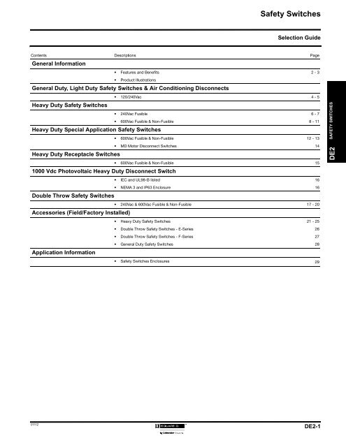
<strong>Safety</strong> <strong>Switches</strong><br />
Selection Guide<br />
Contents Descriptions Page<br />
General Information<br />
• Features and Benefits 2 - 3<br />
• Product Illustrations<br />
General Duty, Light Duty <strong>Safety</strong> <strong>Switches</strong> & Air Conditioning Disconnects<br />
Heavy Duty <strong>Safety</strong> <strong>Switches</strong><br />
Heavy Duty Special Application <strong>Safety</strong> <strong>Switches</strong><br />
Heavy Duty Receptacle <strong>Switches</strong><br />
1000 Vdc Photovoltaic Heavy Duty Disconnect Switch<br />
Double Throw <strong>Safety</strong> <strong>Switches</strong><br />
Accessories (Field/Factory Installed)<br />
Application Information<br />
• 120/240Vac 4 - 5<br />
• 240Vac Fusible 6 - 7<br />
• 600Vac Fusible & Non-Fusible 8 - 11<br />
• 600Vac Fusible & Non-Fusible 12 - 13<br />
• MD Motor Disconnect <strong>Switches</strong> 14<br />
• 600Vac Fusible & Non-Fusible 15<br />
• IEC and UL98-B listed 16<br />
• NEMA 3 and IP63 Enclosure 16<br />
• 240Vac & 600Vac Fusible & Non-Fusible 17 - 20<br />
• Heavy Duty <strong>Safety</strong> <strong>Switches</strong> 21 - 25<br />
• Double Throw <strong>Safety</strong> <strong>Switches</strong> - E-Series 26<br />
• Double Throw <strong>Safety</strong> <strong>Switches</strong> - F-Series 27<br />
• General Duty <strong>Safety</strong> <strong>Switches</strong> 28<br />
• <strong>Safety</strong> <strong>Switches</strong> Enclosures 29<br />
DE2-1<br />
DE2 SAFETY SWITCHES
SAFETY SWITCHES<br />
DE2<br />
<strong>Safety</strong> <strong>Switches</strong><br />
General Information<br />
General Duty<br />
Pages:<br />
DE2-2<br />
DE2-4 to DE2-5<br />
Application: • Residential and light commercial.<br />
• 240 Vac maximum.<br />
• 30 through 600 Amperes.<br />
• Horsepower rated.<br />
• Short Circuit Ratings:<br />
Plug Fuse - up to 10K RMS Symmetrical Amperes Fault Current<br />
Class H, K Fuse - up to 10K RMS Symmetrical Amperes Fault Current<br />
Class R, J Fuse - up to 100K RMS Symmetrical Amperes Fault Current<br />
• Service entrance rated.<br />
Standards: • CSA Certified under file numbers LL-89067 and LL-11815-108C<br />
Enclosures: • Types 1 and 3R<br />
Features: • Visible blades for positive indication that switch is “OFF”.<br />
• Quick-Make / Quick-Break operating mechanism.<br />
• Lugs suitable for AI or Cu conductors.<br />
• Phenolic insulating bases.<br />
• Multiple padlock provisions in the “OFF” position.<br />
• Spring reinforced plated copper fuse clips.<br />
Accessories: • “RB Hubs” for Type 3R enclosures.<br />
• Class R fuse kits.<br />
• Factory or field installable electrical interlock on 60 - 200 Amperes (for F-Series only).<br />
• Field installed fuse pullers on 60 & 100 Amperes.<br />
• See page DE2-28 for more information regarding accessories and optional features.<br />
Heavy Duty<br />
Pages:<br />
DE2-6 to DE2-11<br />
Application: • Commercial and industrial.<br />
• 600 Vac or 600 Vdc maximum.<br />
• 30 through 1200 Amperes.<br />
• Horsepower rated.<br />
• Short Circuit Ratings:<br />
Class H, K Fuse - up to 10 K RMS Symmetrical Amperes Fault Current<br />
Class J, R, L Fuse - up to 200 K RMS Symmetrical Amperes Fault Current<br />
Standards: • CSA Certified under file #’s LL-89067 and LL-97406-3.<br />
Enclosures: • Types 1, 3R, 4/4X and 3R/12<br />
Features:<br />
Accessories:<br />
In addition to General Duty....<br />
• Red and black handles indicate switch position.<br />
• Dual cover interlock.<br />
• Terminations for copper or aluminum and for copper only.<br />
In addition to General Duty....<br />
• <strong>Electric</strong>al interlocks factory or field installed.<br />
• Viewing Windows.<br />
• Factory or field installed fuse pullers.<br />
• Key interlock systems.<br />
• Factory installed push buttons.<br />
• Factory installed indicators of voltage presence on line/load side.<br />
• Lock-off guard.<br />
• Internal barrier kits.<br />
• See pages DE2-21 to DE2-25 for more information regarding accessories and optional features.<br />
01/12
01/12<br />
Pages:<br />
Arktite ® is a Registered Trademark of Crouse-Hinds Company.<br />
Appleton ® is a Registered Trademark of Appleton <strong>Electric</strong> Limited.<br />
DE2-17 to DE2-20<br />
<strong>Safety</strong> <strong>Switches</strong><br />
General Information<br />
Double Throw<br />
Application: • Manual transfer of a load between two power sources (or one power source<br />
between two loads on series A, F DT & DTU only)<br />
• Residential, light commercial and industrial installations.<br />
• Up to 600 Vac or 600 Vdc maximum.<br />
• 30 through 600 Amperes.<br />
Standards: • cULus<br />
Enclosures: • Types 1, 3R, 4/4X and 12.<br />
Features: • Visible blades for positive indication switch is “OFF”.<br />
• Padlock provisions in the center “OFF” position.<br />
• Padlock provisions in the “ON” positions<br />
• Quick-Make / Quick-Break operating mechanism, Load-Make / Load-Break rated<br />
on Types DT & DTU (series A, F), 82,000.<br />
• Dual cover interlock on the 82,000 line & A, F-Series devices with external defeat<br />
mechanism<br />
• Series A, F, Types DT & DTU, supplied as standard for switching one load between<br />
two power sources, and may be field converted to switch one power source<br />
between two loads<br />
Accessories: • “RB” Bolt-on hubs for Type 3R enclosures.<br />
• Field installable service grounding kits for Series E switches. Included as standard<br />
on Series F switches.<br />
• Neutral assemblies and electrical interlocks are available for field installation only<br />
on series A, F, Types DT & DTU, 82,000.<br />
• Factory installed indicators of voltage presence on line/load side(s) on Types DT &<br />
DTU (series F).<br />
• See pages DE2-26 and DE2-27 for more information regarding accessories and<br />
optional features.<br />
Special Applications<br />
Pages: DE2-12 to DE2-14<br />
• Type 4X, non-metallic, corrosion resistant, fiberglass reinforced polyester enclosed<br />
switches.<br />
• Type 7/9 enclosed switches, for hazardous locations.<br />
• Types 1 and 3R/12, 4-Pole safety switches (see pages DE2-10 and DE2-11).<br />
• Types 3R/12, 6-Pole safety switches (see pages DE2-10 and DE2-11).<br />
• Types 4/4X stainless steel and 3R/12 interlocked receptacle switches, with<br />
Crouse-Hinds Arktite ® Receptacles (see page DE2-14).<br />
• Types 4/4X stainless steel and 3R/12 interlocked receptacle switches,<br />
with Appleton ® Receptacles (see page DE2-14).<br />
DE2-3<br />
DE2 SAFETY SWITCHES
SAFETY SWITCHES<br />
DE2<br />
<strong>Safety</strong> <strong>Switches</strong><br />
General Duty, Light Duty & Air Conditioning Disconnects<br />
Single Throw<br />
120/240 Vac, 1-Pole, 2-Pole & 3-Pole<br />
HP Rating r<br />
System Amps Type of Voltage Ser. Type 1 Ser. Type 3R Std. Max.<br />
Fuse Vac 1 3 13 Light Duty <strong>Switches</strong><br />
General Duty 2-Pole + S/N<br />
General Duty 3-Pole + S/N<br />
• Fusible switches are suitable for use as service equipment except where marked .<br />
Not suitable for use as service equipment.<br />
Does not contain over current protection. Suitable for use on systems with up to 10,000 RMS Symmetrical Amperes available fault current at 240Vac max when<br />
protected by a fuse or circuit breaker rated 60A or less.<br />
• Type 3R <strong>Switches</strong> with ”RB” suffix are supplied with main entry hole cut in top endwall and closing cap (BCAP) installed. Hole accepts 3/4 in. to 2 1/2 in. hubs.<br />
• “Ser.” denotes the Series of the device. Please refer to this column when selecting accessories.<br />
For 200% neutral, order (1) additional neutral kit CSN20, and (1) neutral jumper kit SN20NI.<br />
DE2-4<br />
30 Plug 120 E2 L111N ---- ---- 0.5 ---- 2 ----<br />
30 Plug 120/240 E2 CD211N ---- ---- 1.5 ---- 3 ----<br />
30 E2 CD221N ---- ---- 1.5 ---- 3 ----<br />
60 F1 CD222N F1 CD222NRB 3 ---- 10 ----<br />
100 Cartridge 120/240 F3 CD223N F3 CD223NRB 7.5 ---- 15 ----<br />
200 F1 CD224N F1 CD224NRB 15 ---- ---- ----<br />
400 E3 CD225N E1 CD225NR ---- ---- ---- ----<br />
600 E3 CD226N E1 CD226NR ---- ---- ---- ----<br />
30 E3 CD321N E3 CD321NRB 1.5 3 3 7.5<br />
60 F1 CD322N F1 CD322NRB 3 7.5 10 15<br />
100 Cartridge 120/240 F3 CD323N F3 CD323NRB 7.5 15 15 30<br />
200 F1 CD324N F1 CD324NRB 15 25 ---- 60<br />
400 E3 CD325N E1 CD325NR ---- 50 ---- 125<br />
600 E3 CD326N E1 CD326NR ---- 75 ---- 150<br />
Unfused Air Conditioning Disconnect - Moulded Case Switch<br />
Application Information<br />
60 ---- 240 ---- ---- G3 CQO200TR ---- ---- 10 ----<br />
r HP Ratings:<br />
- Standard - using fast acting one time fuses<br />
- Maximum - using time delay fuses<br />
•General Duty <strong>Switches</strong> have Quick-Make / Quick-Break<br />
operating mechanisms and Load-Make / Load-Break rated.<br />
•Light Duty <strong>Switches</strong> have Slow-Make / Slow-Break operating<br />
mechanisms and are Load-Make / Load-Break rated.<br />
•For information regarding accessories and optional<br />
features, see page DE2-28.<br />
• For more information consult <strong>Schneider</strong> <strong>Electric</strong>.<br />
•Short Circuit Withstand Ratings<br />
RMS Symmetrical k Amps<br />
Fuse Class<br />
Voltage Plug H K J R<br />
240 Vac 10 10 10 100 100<br />
• Class J fuse provisions available on 400 & 600A only,<br />
(page DE2-28).<br />
01/12
Approximate Dimensions - Light Duty Type 1<br />
01/12<br />
Catalogue Height (H) Width (W) W/H Depth (D)<br />
Number in./mm in./mm in./mm in./mm<br />
L111N 7.63/194 5.00/127 6.13/156 4.00/102<br />
Approximate Dimensions - General Duty Type 1<br />
Ampere Height (H) Width (W) W/H Depth (D)<br />
Rating in./mm in./mm in./mm in./mm<br />
30 9.25/235 6.75/171 7.25/184 3.63/92<br />
60 14.63/372 6.50/165 7.45/189 4.88/124<br />
100 17.50/445 8.50/216 10.50/267 6.50/165<br />
200 29.00/737 17.25/438 19.00/483 8.25/210<br />
400 45.12/1146 24.00/610 24.88/632 8.88/226<br />
600 49.13/1248 24.00/610 24.88/632 8.88/226<br />
Approximate Dimensions - General Duty Type 3R<br />
Ampere Height (H) Width (W) W/H Depth (D)<br />
Rating in./mm in./mm in./mm in./mm<br />
30 9.63/245 7.25/184 7.75/197 3.75/95<br />
60 14.88/378 6.63/168 7.45/189 4.88/124<br />
100 17.50/445 8.50/216 10.50/267 6.50/165<br />
200 29.25/743 17.25/438 19.00/483 8.25/210<br />
400 30.63/778 21.38/543 22.25/565 10.13/257<br />
600 49.13/1248 24.75/629 25.13/638 8.88/226<br />
Terminal Lug Data <br />
Ampere<br />
Rating<br />
Conductors<br />
per Phase<br />
Wire Range<br />
AWG/Kcmil<br />
30 1 # 12 - 6 (Al) or # 14 - 6 (Cu)<br />
60 1 # 10 - 3 (Al) or # 14 - 3 (Cu)<br />
100 1 # 12 - 1 (Al) or # 14 - 1 (Cu)<br />
200 1 # 6 - 250 (Al/Cu)<br />
400<br />
Type 1<br />
1<br />
or<br />
2<br />
#1/0 - 750 (Al/Cu) or<br />
#1/0 - 300 (Al/Cu)<br />
400<br />
Type 3R<br />
2 #1/0 - 250 (Al/Cu)<br />
600 2 # 4 - 500 (Al/Cu)<br />
Optional wire range: (1) 1/0 - 600 or, (2) 1/0 - 500 or (4) 1/0 - 250 when lug kit GD 4060 LK is used. Kit applicable to Type 1 enclosures only.<br />
30-100 Amp switches suitable for 60 or 75C conductors. 200-600 Amp switches suitable for 75C conductors.<br />
Approximate Dimensions - Air Conditioning Disconnects<br />
<strong>Safety</strong> <strong>Switches</strong><br />
General Duty<br />
Typical Type 1 Enclosure<br />
Typical Type 3R Enclosure<br />
Ampere Height (H) Width (W) Depth (D) Conductors Wire<br />
Rating in./mm in./mm in./mm Per Phase Range<br />
CQ0200TR 60 6.50/165 4.63/118 3.88/99 1 #14-#4 Al/Cu<br />
Application Information<br />
•Dimensions are approximate only. Do not use for construction.<br />
Single Throw<br />
120/240 Volt<br />
DE2-5<br />
DE2 SAFETY SWITCHES
SAFETY SWITCHES<br />
DE2<br />
<strong>Safety</strong> <strong>Switches</strong><br />
Heavy Duty<br />
Single Throw - Fusible<br />
240 Vac, 250 Vdc, 2-Pole & 3-Pole<br />
System Amps<br />
2-Pole + S/N<br />
3-Pole + S/N<br />
• Type 3R switches with “RB” suffix are supplied with main entry hole cut in top endwall and closing cap (BCAP) installed. Hole accepts 3/4 in. to 2 1/2 in. hubs.<br />
• Type 3R switches with “R” suffix have a blank endwall.<br />
• Type 3R/12 switches are suitable for Type 3R application by removing the drainscrew from bottom endwall.<br />
• “Ser.” denotes the Series of the device. Please refer to this column when selecting accessories.<br />
• For switching DC, use any two switching poles.<br />
• Fusible switches 240V are suitable for use as service equipment.<br />
• For installing class J fuses:<br />
- Relocation of the load side fuse base assembly is required in 100-400 A, 240V switches.<br />
- Addition of an adapter kit H600J is required in 600A switches.<br />
• 30-600 A 240V switches accept class R fuses as standard.<br />
For class R fuse rejection kit information please refer to page DE2-21.<br />
Type 3R/12, 4/4X 30-200A are supplied with viewing window standard.<br />
DE2-6<br />
Fuse<br />
Type<br />
Provision<br />
Ser. Type 1 Ser. Type 3R Ser. Type 4/4X Ser. Type 3R/12<br />
HP Rating r<br />
240 Vac 250 Vdc<br />
Stainless Steel Std. Max.<br />
1Ø 3Ø 1Ø 3Ø<br />
30 H F5 CH221N F5 CH221NRB - - F6 CH221NAWK 1.5 3 5<br />
60 H F5 CH222N F5 CH222NRB - - F6 CH222NAWK 3 10 10<br />
100 H F5 CH223N F5 CH223NRB - - F6 CH223NAWK 7.5 15 20<br />
200 H F5 CH224N F5 CH224NRB - - F6 CH224NAWK 15 - 40<br />
400 H E4 CH225N E5 CH225NR - - E4 CH225NAWK - - 50<br />
600 H E4 CH226N E5 CH226NR - - E4 CH226NAWK - - 50<br />
800 L E4 H227N E4 H227NR - - E4 H227NAWK 50 50 50<br />
1200 L E4 H228N E4 H228NR - - E4 H228NAWK 50 50 50<br />
1Ø 3Ø 1Ø 3Ø<br />
30 H F5 CH321N F5 CH321NRB F6 CH321NDS F6 CH321NAWK 1.5 3 3 7.5 5<br />
60 H F5 CH322N F5 CH322NRB F6 CH322NDS F6 CH322NAWK 3 7.5 10 15 10<br />
100 H F5 CH323N F5 CH323NRB F6 CH323NDS F6 CH323NAWK 7.5 15 15 30 20<br />
200 H F5 CH324N F5 CH324NRB F6 CH324NDS F6 CH324NAWK 15 25 - 60 40<br />
400 H E4 CH325N E5 CH325NR E4 CH325NDS E1 CH325NAWK - 50 - 125 50<br />
600 H E4 CH326N E5 CH326NR E4 CH326NDS E4 CH326NAWK - 75 - 200 50<br />
800 L E4 H327N E4 H327NR - - E4 H327NAWK 50 100 50 250 50<br />
1200 L E4 H328N E4 H328NR - - E4 H328NAWK 50 100 50 250 50<br />
Application Information<br />
r HP Ratings:<br />
- Standard - using fast acting one time fuses<br />
- Maximum - using time delay fuses<br />
- refer to latest design series only<br />
• Heavy Duty <strong>Switches</strong> have Quick-Make / Quick-Break<br />
operating mechanisms Load-Make / Load-Break rated.<br />
•For information regarding accessories and optional<br />
features, see pages DE2-21 to DE2-25.<br />
• For more information consult <strong>Schneider</strong> <strong>Electric</strong>.<br />
• Short Circuit Current Ratings i<br />
RMS Symmetrical k Amps<br />
Fuse Class<br />
Voltage H J L R<br />
600 Vac 10 200 200 200<br />
i Apply to AC only.<br />
01/12
Approximate Dimensions - Type 1<br />
01/12<br />
Ampere<br />
Rating<br />
Height (H)<br />
in./mm<br />
Width (W)<br />
in./mm<br />
W/H<br />
in./mm<br />
Depth (D)<br />
in./mm<br />
30 14.60/371 6.50/165 7.55/192 4.88/124<br />
60 14.60/371 6.50/165 7.55/192 4.88/124<br />
100 21.25/540 8.50/216 10.50/267 6.38/162<br />
200 29.00/737 17.13/435 18.50/470 8.25/210<br />
400 2-pole 50.25/1276 27.63/702 27.63/702 10.13/257<br />
400 3-pole 50.25/1276 27.88/708 27.88/708 10.13/257<br />
600 50.25/1276 27.63/702 27.63/702 10.13/257<br />
800 69.13/1756 36.62/930 36.63/929 17.75/451<br />
1200 69.13/1756 36.62/930 36.63/929 17.75/451<br />
Approximate Dimensions - Type 3R<br />
Ampere<br />
Rating<br />
Height (H)<br />
in./mm<br />
Width (W)<br />
in./mm<br />
W/H<br />
in./mm<br />
Depth (D)<br />
in./mm<br />
30 14.88/378 6.63/168 7.55/192 4.88/124<br />
60 14.88/378 6.63/168 7.55/192 4.88/124<br />
100 21.25/540 8.50/216 10.50/267 6.38/162<br />
200 29.25/743 17.25/438 18.63/473 8.50/216<br />
400 50.31/1278 27.76/705 27.76/705 9.53/257<br />
600 50.31/1278 27.76/705 27.76/705 9.53/257<br />
800 69.13/1756 36.62/930 36.63/929 17.75/451<br />
1200 69.13/1756 36.62/930 36.63/929 17.75/451<br />
Approximate Dimensions - Type 4/4X<br />
Ampere<br />
Rating<br />
Height (H)<br />
in./mm<br />
Width (W)<br />
in./mm<br />
W/H<br />
in./mm<br />
Depth (D)<br />
in./mm<br />
30 14.93/379 7.22/183 8.67/220 5.11/130<br />
60 14.93/379 7.22/183 8.67/220 5.11/130<br />
100 20.82/529 9.36/238 11.25/286 6.97/177<br />
200 29.00/737 17.75/451 19.25/489 8.88/226<br />
400 46.25/1175 26.25/667 26.25/667 10.13/259<br />
600 46.25/1175 26.25/667 26.25/667 10.13/259<br />
800 - - - -<br />
1200 - - - -<br />
Approximate Dimensions - Type 3R/12<br />
Ampere<br />
Rating<br />
Height (H)<br />
in./mm<br />
Width (W)<br />
in./mm<br />
W/H<br />
in./mm<br />
Depth (D)<br />
in./mm<br />
30 14.60/371 6.63/168 7.55/192 4.96/126<br />
60 14.60/371 6.63/168 7.55/192 4.96/126<br />
100 20.50/521 9.00/229 10.50/267 7.00/178<br />
200 29.00/737 17.25/438 18.63/473 8.75/216<br />
400 46.25/1175 26.25/667 26.25/667 10.13/259<br />
600 46.25/1175 26.25/667 26.25/667 10.13/259<br />
800 69.13/1756 36.63/929 36.63/929 17.75/451<br />
1200 69.13/1756 36.63/929 36.63/929 17.75/451<br />
Application Information<br />
•Dimensions are approximate only. Do not use for construction.<br />
•For terminal lug data refer to page DE2-24.<br />
Typical 30-200 A Type 1 Enclosure<br />
Typical 30-200 A Type 3R Enclosure<br />
<strong>Safety</strong> <strong>Switches</strong><br />
Heavy Duty<br />
Single Throw - Fusible<br />
240 Vac, 250 Vdc<br />
Typical 30-200 A Type 4, 4X, 5, 12 Enclosure<br />
(Stainless has flat front)<br />
DE2-7<br />
DE2 SAFETY SWITCHES
SAFETY SWITCHES<br />
DE2<br />
<strong>Safety</strong> <strong>Switches</strong><br />
Heavy Duty<br />
Single Throw - Fusible & Non-Fusible<br />
600 Vac, 600 Vdc, 3-Pole<br />
System Amps<br />
3-Pole, Fusible<br />
• Type 3R switches with “RB” suffix are supplied with main entry hole cut in top endwall and closing cap (BCAP) installed. Hole accepts 3/4 in. to 2 1/2 in. hubs.<br />
• Type 3R switches with “R” suffix have a blank endwall.<br />
• Type 3R/12 switches are suitable for Type 3R application by removing the drainscrew from bottom endwall.<br />
• “Ser.” denotes the Series of the device. Please refer to this column when selecting accessories.<br />
• 30-200 A switches are silicone free devices.<br />
• Fusible switches are suitable for use as service equipment when installed with a neutral kit (page DE2-22).<br />
• Provisions for installing class H, R fuses are included in 30-200 A 600V fusible switches. Relocation of the load side fuse base assembly is required.<br />
• For installing class J fuses:<br />
- Relocation of the load side fuse base assembly is required in 400A, 600V fusible switches.<br />
- Addition of an adapter kit H600J is required in 600A, 600V fusible switches.<br />
Use outside two poles for switching DC.<br />
Type 3R/12, 4/4X are supplied with viewing window standard.<br />
DE2-8<br />
Fuse<br />
Type<br />
Provision<br />
HP Rating r<br />
Ser. Type 1 Ser. Type 3R Ser. Type 4/4X Ser. Type 3R/12 240 Vac 480 Vac 600Vac<br />
250<br />
Vdc<br />
Stainless Steel Std. Max. Std. Max. Std. Max <br />
30 J F5 CH361 F5 CH361RB F6 CH361DS F5 CH361AWK - - 5 15 7.5 20 5 15<br />
60 J F5 CH362 F5 CH362RB F6 CH362DS F6 CH362AWK - - 15 30 15 50 10 30<br />
100 J F5 CH363 F5 CH363RB F6 CH363DS F6 CH363AWK - - 25 60 30 75 20 50<br />
200 J F5 CH364 F5 CH364RB F6 CH364DS F6 CH364AWK - - 50 125 60 150 40 50<br />
400 H E4 CH365 E4 CH365R E4 CH365DS E4 CH365AWK - - 100 250 125 350 50 50<br />
600 H E4 CH366 E4 CH366R E4 CH366DS E4 CH366AWK - - 150 400 200 500 50 50<br />
800 L E4 H367 E4 H367R - - E4 H367AWK - - 200 500 250 500 50 50<br />
1200 L E4 H368 E4 H368R - - E4 H368AWK - - 200 500 250 500 50 50<br />
3-Pole, Non-Fusible<br />
1Ø 3Ø 1Ø 3Ø 1Ø 3Ø<br />
30 - F5 CHU361 F5 CHU361RB F6 CHU361DS F6 CHU361AWK 5 10 7 1/2 20 10 30 5 15<br />
60 - F5 CHU362 F5 CHU362RB F6 CHU362DS F6 CHU362AWK 10 20 25 50 30 60 10 30<br />
100 - F5 CHU363 F5 CHU363RB F6 CHU363DS F6 CHU363AWK 20 40 40 75 40 100 20 50<br />
200 - F5 CHU364 F5 CHU364RB F6 CHU364DS F6 CHU364AWK 15 60 50 125 50 150 40 50<br />
400 - E4 CHU365 E5 CHU365R E4 CHU365DS E4 CHU365AWK - 125 - 250 - 350 50 50<br />
600 - E4 CHU366 E5 CHU366R E4 CHU366DS E4 CHU366AWK - 200 - 400 - 500 50 50<br />
800 - E4 HU367 E4 HU367R - - E4 HU367AWK 50 250 50 500 50 500 50 50<br />
1200 - E4 HU368 E4 HU368R - - E4 HU368AWK 50 250 50 500 50 500 50 50<br />
Application Information<br />
r Hp Ratings for fusible switches:<br />
- Standard - using fast acting one time fuses<br />
- Maximum - using time delay fuses<br />
- refer to latest design series only<br />
• Heavy Duty <strong>Switches</strong> have Quick-Make / Quick-Break<br />
operating mechanisms Load-Make / Load-Break rated.<br />
•For information regarding accessories and optional<br />
features, see pages DE2-21 to DE2-25.<br />
• For more information consult <strong>Schneider</strong> <strong>Electric</strong>.<br />
l For CSA certified short-circuit current rating for Square D<br />
Heavy Duty, Non Fused switches, please refer to page<br />
DE2-21.<br />
• Short Circuit Current Ratings l i<br />
RMS Symmetrical k Amps<br />
Fuse Class<br />
Voltage H J L R<br />
600 Vac 10 200 200 200<br />
i Apply to AC only.<br />
600<br />
Vdc<br />
01/12
Approximate Dimensions - Type 1<br />
01/12<br />
Ampere Height (H) Width (W) W/H Depth (D)<br />
Rating in./mm in./mm in./mm in./mm<br />
30 14.60/371 6.50/165 7.55/192 4.88/124<br />
60 17.50/445 9.00/229 10.50/267 6.38/162<br />
100 21.25/540 8.50/216 10.50/267 6.38/162<br />
200 29.00/737 17.13/435 18.50/470 8.25/210<br />
400 50.25/1276 27.63/702 27.63/702 10.13/257<br />
600 50.25/1276 27.63/702 27.63/702 10.13/257<br />
800 69.13/1756 36.62/930 36.62/930 17.75/451<br />
1200 69.13/1756 36.62/930 36.62/930 17.75/451<br />
Approximate Dimensions - Type 3R<br />
Ampere Height (H) Width (W) W/H Depth (D)<br />
Rating in./mm in./mm in./mm in./mm<br />
30 14.88/378 6.63/168 7.55/192 4.88/124<br />
60 17.50/445 9.00/229 10.50/267 6.38/162<br />
100 21.25/540 8.50/216 10.50/267 6.38/162<br />
200 29.25/743 17.25/438 18.63/473 8.50/216<br />
400 50.31/1278 27.76/705 27.76/705 9.53/257<br />
600 50.31/1278 27.76/705 27.76/705 9.53/257<br />
800 69.13/1756 36.62/930 36.62/930 17.75/451<br />
1200 69.13/1756 36.62/930 36.62/930 17.75/451<br />
Approximate Dimensions - Type 4/4X<br />
Ampere Height (H) Width (W) W/H Depth (D)<br />
Rating in./mm in./mm in./mm in./mm<br />
30 14.93/379 7.22/183 8.67/220 5.11/130<br />
60 16.87/428 8.92/227 10.81/275 6.97/177<br />
100 20.82/529 9.36/238 11.25/286 6.97/177<br />
200 29.00/737 17.75/451 19.25/489 8.88/226<br />
400 46.25/1175 26.25/667 26.25/667 10.13/259<br />
600 46.25/1175 26.25/667 26.25/667 10.13/259<br />
800 - - - -<br />
1200 - - - -<br />
Approximate Dimensions - Type 3R/12<br />
Ampere Height (H) Width (W) W/H Depth (D)<br />
Rating in./mm in./mm in./mm in./mm<br />
30 14.60/371 6.63/168 7.55/192 4.96/126<br />
60 16.50/419 9.00/229 10.50/267 7.00/178<br />
100 20.50/521 9.00/229 10.50/267 7.00/178<br />
200 29.00/737 17.25/438 18.63/473 8.75/216<br />
400 46.25/1175 26.25/667 26.25/667 10.13/259<br />
600 46.25/1175 26.25/667 26.25/667 10.13/259<br />
800 69.13/1756 36.62/930 36.62/930 17.75/451<br />
1200 69.13/1756 36.62/930 36.62/930 17.75/451<br />
Application Information<br />
•Dimensions are approximate only. Do not use for construction.<br />
•For terminal lug data refer to page DE2-24.<br />
<strong>Safety</strong> <strong>Switches</strong><br />
Heavy Duty<br />
Single Throw - Fusible & Non-Fusible<br />
600 Volt<br />
Typical Type 1 Enclosure<br />
Typical Type 3R Enclosure<br />
Typical Type 4, 4X, 5, 12 Enclosure<br />
(Stainless has flat front)<br />
DE2-9<br />
DE2 SAFETY SWITCHES
SAFETY SWITCHES<br />
DE2<br />
<strong>Safety</strong> <strong>Switches</strong><br />
Heavy Duty<br />
Single Throw - Fusible & Non-Fusible<br />
600 Volt, 4 & 6 Pole (Not Suitable for Service Equipment)<br />
System Amps Fuse<br />
Type<br />
Provision<br />
4-Pole, Fusible<br />
• Type 3R/12 <strong>Switches</strong> are suitable for type 3R application by removing the drainscrew from bottom endwall.<br />
• “Ser.” denotes the Series of the device. Please refer to this column when selecting accessories.<br />
• 30-200 A switches are silicone free devices.<br />
• Not suitable for use as service equipment.<br />
Use outside two poles for switching DC<br />
For applications requiring motor disconnect capability, use electrical interlock. Refer to page DE2-23.<br />
No knockouts are provided<br />
HP rating for Non-Fusible switches are 2Ø & 3Ø (Not Std & Max).<br />
s 600 Vac only<br />
HU461AWK (Series E1) is rated 5 HP@250 Vdc, 10HP@600 Vdc.<br />
DE2-10<br />
HP Rating r<br />
Ser. Type 1 Ser. Type 3R Ser. Type 4/4X Ser. Type 3R/12 240 480 600 250 600<br />
Stainless Steel<br />
Vac Vac Vac Vdc Vdc<br />
Std. Max. Std. Max. Std. Max. <br />
30 H F5 H461 - - F6 H461DS F6 H461AWK - - 7 1/2 20 10 25 5 15<br />
60 H F5 H462 - - F6 H462DS F5 H462AWK - - 15 40 20 50 10 30<br />
100 H F5 H463 - - F6 H463DS F6 H463AWK - - 25 50 30 75 20 30<br />
200 H F5 H464 - - F6 H464DS F6 H464AWK - - 50 - 50 - 40 50<br />
400 H E4 CH465 s - - - - E4 CH465AWK s - - - - - - - -<br />
600 H E4 CH466 s - - - - - - - - - - - - - -<br />
4-Pole, Non-Fusible <br />
6-Pole, Fusible<br />
30 - F5 HU461 - - F6 HU461DS E1 HU461AWK 10 10 20 20 25 30 1015 60 - F5 HU462 - - F6 HU462DS F6 HU462AWK 20 20 40 50 50 60 10 30<br />
100 - F5 HU463 - - F6 HU463DS F6 HU463AWK 30 40 50 75 50 75 20 30<br />
200 - F5 HU464 - - F6 HU464DS F6 HU464AWK 50 60 50 125 50 150 40 50<br />
400 - E4 CHU465 s - - - - E4 CHU465AWK s - - - - - - - -<br />
600 - E4 CHU466 s - - - - E4 CHU466AWK s - - - - - - - -<br />
30 - - - - - - - - - - - - - - - - -<br />
60 - - - - - - - - - - - - - - - - -<br />
100 H - - - - F6 H663DS F6 H663AWK - - 25 60 30 75 - -<br />
200 H - - - - F6 H664DS F6 H664AWK - - - - - - - -<br />
6-Pole, Non-Fusible <br />
30 - - - - - F6 HU661DS F6 HU661AWK - 10 - 20 - 30 - -<br />
60 - - - - - F6 HU662DS F6 HU662AWK - 20 - 50 - 60 - -<br />
100 - - - - - F6 HU663DS F6 HU663AWK - 40 - 75 - 75 - -<br />
200 - - - - - F6 HU664DS F6 HU664AWK - 60 - 125 - 150 - -<br />
Application Information<br />
r HP Ratings for Fusible <strong>Switches</strong>:<br />
- Standard - using fast acting one time fuses<br />
- Maximum - using time delay fuses<br />
- refer to latest design series only<br />
• Heavy Duty <strong>Switches</strong> have Quick-Make / Quick-Break<br />
operating mechanisms Load-Make / Load-Break rated.<br />
•For information regarding accessories and optional<br />
features, see pages DE2-21 to DE2-25.<br />
• For more information consult <strong>Schneider</strong> <strong>Electric</strong>.<br />
l The CSA certified short-circuit current rating for Square D<br />
Heavy Duty, Non Fused switches, please refer to page<br />
DE2-21.<br />
• Short Circuit Current Ratings l i<br />
RMS Symmetrical k Amps<br />
Fuse Class<br />
Voltage H J L R<br />
600 Vac 10 200 200 200<br />
i Apply to AC only.<br />
01/12
Approximate Dimensions - 4-Pole, Type 1<br />
Except HU461AWK.<br />
01/12<br />
Ampere Height (H) Width (W) W/H Depth (D)<br />
Rating in./mm in./mm in./mm in./mm<br />
30 20.50/521 14.75/375 16.13/410 6.85/174<br />
60 20.50/521 14.75/375 16.13/410 6.85/174<br />
100 20.50/521 14.75/375 16.13/410 6.85/174<br />
200 29.00/737 23.25/591 24.88/632 8.75/222<br />
400 50.25/1276 33.88/861 33.88/861 10.13/257<br />
600 50.25/1276 33.88/861 33.88/861 10.13/257<br />
Approximate Dimensions - 4-Pole, Type 4/4X<br />
Ampere Height (H) Width (W) W/H Depth (D)<br />
Rating in./mm in./mm in./mm in./mm<br />
30 20.82/529 15.08/383 16.85/428 6.85/174<br />
60 20.82/529 15.08/383 16.85/428 6.85/174<br />
100 20.82/529 15.08/383 16.85/428 6.85/174<br />
200 29.00/737 23.75/603 25.25/641 8.88/226<br />
Approximate Dimensions - 4-Pole, Type 3R/12<br />
Ampere Height (H) Width (W) W/H Depth (D)<br />
Rating in./mm in./mm in./mm in./mm<br />
30 20.50/521 14.75/375 16.13/410 6.80/173<br />
HU461AWK 16.63/422 9.88/251 11.00/279 6.13/156<br />
60 20.50/521 14.75/375 16.13/410 6.80/173<br />
100 20.50/521 14.75/375 16.13/410 6.80/173<br />
200 29.00/737 23.25/591 24.88/632 8.75/222<br />
400 46.25/1175 32.50/826 32.50/826 10.13/259<br />
600 46.25/1175 32.50/826 32.50/826 10.13/259<br />
Approximate Dimensions - 6-Pole, Type 4/4X<br />
Ampere Height (H) Width (W) W/H Depth (D)<br />
Rating in./mm in./mm in./mm in./mm<br />
30 20.82/529 15.08/383 16.85/428 6.97/177<br />
60 20.82/529 15.08/383 16.85/428 6.97/177<br />
100 20.82/529 15.08/383 16.85/428 6.97/177<br />
200 29.00/737 23.75/603 25.25/641 8.88/226<br />
Approximate Dimensions - 6-Pole, Type 3R/12<br />
Ampere Height (H) Width (W) W/H Depth (D)<br />
Rating in./mm in./mm in./mm in./mm<br />
30 20.50/521 14.75/375 16.13/410 6.80/173<br />
60 20.50/521 14.75/375 16.13/410 6.80/173<br />
100 20.50/521 14.75/375 16.13/410 6.80/173<br />
200 29.00/737 23.25/591 24.88/632 8.75/222<br />
Application Information<br />
•Dimensions are approximate only. Do not use for construction.<br />
•For terminal lug data refer to page DE2-24.<br />
<strong>Safety</strong> <strong>Switches</strong><br />
Heavy Duty<br />
Single Throw - Fusible & Non-Fusible<br />
600 Volt, 4 & 6-Pole<br />
Typical Type 1 Enclosure<br />
Typical Type 3R Enclosure<br />
Typical Type 4, 4X, 5, 12 Enclosure<br />
(Stainless has flat front)<br />
DE2-11<br />
DE2 SAFETY SWITCHES
SAFETY SWITCHES<br />
DE2<br />
<strong>Safety</strong> <strong>Switches</strong><br />
Heavy Duty, Special Application<br />
Single Throw<br />
600 Volt, 3-Pole<br />
316 Grade Stainless Steel–Type 3, 3R, 4, 4X, 5, 12<br />
Type 316 stainless steel enclosure safety switches offer superior corrosion resistance to a wider range of chemicals than Type 304 stainless switches. Type 316 resists chloride<br />
attacks and is often used in marine, waste treatment and transportation applications. Use watertight hubs from page DE2-24. Equipment ground lugs are supplied as standard.<br />
(For Type 304 stainless switches see page DE2-8.) Fusible switches are suitable for use as service equipment when installed with a neutral kit (page DE2-22).<br />
3-pole 600 Vac, 600 Vdc<br />
HP Rating 3Ø r<br />
System<br />
Fusible<br />
Amps<br />
Fuse Type<br />
Provision<br />
Ser.<br />
Catalogue<br />
Number<br />
Std.<br />
480 Vac<br />
Max. Std.<br />
600 Vac<br />
Max.<br />
600 Vdc<br />
Max.<br />
30 H F6 H361SS 5 15 7.5 20 15<br />
60 H F6 H362SS 15 30 15 50 30<br />
100 H F6 H363SS 25 60 30 75 50<br />
Non-Fusible<br />
200 H F6 H364SS 50 125 60 150 50<br />
30 - F6 HU361SS - 20 - 30 15<br />
60 - F6 HU362SS - 50 - 60 30<br />
100 - F6 HU363SS - 75 - 100 50<br />
200 - F6 HU364SS - 125 - 150 50<br />
Fiberglass Reinforced Polyester Enclosures - Type 4X<br />
Fiberglass Reinforced Polyester enclosures are watertight, corrosion resistant and impervious to windblown dust, rain, and splashing liquid. The moulded fiberglass is<br />
extremely stable in a wide range of operating temperatures and can withstand heavy impact. <strong>Switches</strong> are furnished with hubs and equipment ground lugs. Fusible<br />
switches are suitable for use as service equipment when installed with a neutral kit (page DE2-22).<br />
HP Rating 3Ø<br />
System<br />
Fusible<br />
Amps<br />
Fuse Type<br />
Provision<br />
Ser.<br />
Catalogue<br />
Number<br />
Std.<br />
480 Vac<br />
Max. Std.<br />
600 Vac<br />
Max.<br />
600 Vdc<br />
Max.<br />
30 H F1 H361DF 5 15 7.5 20 15<br />
60 H F1 H362DF 15 30 15 50 30<br />
100 H F1 H363DF 25 60 30 75 50<br />
Non-Fusible<br />
200 H E1 H364DF 50 125 60 150 50<br />
30 - F1 HU361DF - 20 - 30 15<br />
60 - F1 HU362DF - 50 - 60 30<br />
100 - F1 HU363DF - 75 - 100 50<br />
200 - E1 HU364DF - 125 - - 50<br />
Type 7/9 Enclosures<br />
An enclosed automatic moulded case switch for use in a Class I, Groups C & D. Division 1 or 2, (Type 7); Class II, Groups E, F, & G, Division 1 or 2, (Type 9); or Class<br />
III, Division 1 or 2, (Type 9).<br />
Furnished with threaded conduit openings in both top and bottom endwall (page DE2-13).<br />
Not suitable for use as service equipment, and listed as “Raintight” for outdoor applications.<br />
3-Pole, Unfused, 600Vac, 250Vdc Maximum, Short Circuit Rating 10 000 AIR.<br />
System Amps Ser.<br />
Catalogue<br />
Number<br />
240 Vac<br />
HP Rating 3Ø<br />
480 Vac 600 Vac<br />
60 E1 H60XFA 15 30 50<br />
100 E1 H100XFA 30 60 75<br />
225A A1 H225XJG 60 125 150<br />
Includes PKDB-1, breather and drain kit, required for rain proof application - Type 7 only.<br />
<strong>Electric</strong>al Interlocks not available. For auxiliary switches, add 1212 suffix to standard switch catalogue number and price adder (e.g. H60XFA1212)<br />
Auxiliary Interlocks factory Installed only.<br />
Not CSA certified or UL listed due to wire bending space requirements.<br />
• “Ser.” denotes the Series of the device. Please refer to this column when selecting accessories.<br />
Application Information<br />
r HP Ratings:<br />
- Standard - using fast acting one time fuses<br />
- Maximum - using time delay fuses<br />
- refer to latest design series only<br />
• Heavy Duty <strong>Switches</strong> have Quick-Make / Quick-Break<br />
operating mechanisms Load-Make / Load-Break rated.<br />
•For information regarding accessories and optional<br />
features, see pages DE2-21 to DE2-25.<br />
• For more information consult <strong>Schneider</strong> <strong>Electric</strong>.<br />
DE2-12<br />
l The CSA certified short-circuit current rating for Square D<br />
Heavy Duty, Non Fused switches is based on the switch<br />
being used in conjunction with fuses. Evaluation of not<br />
fused switches in conjunction with molded case circuit<br />
breakers has not been performed. If a CSA certified shortcircuit<br />
current rating is required, this not fused switch must<br />
be replaced with a SQUARE D Heavy Duty Fusible safety<br />
switch equipped with the appropriate class and size fusing.<br />
Consult the wiring diagram of the switch to verify the<br />
CSA certified short-circuit current rating.<br />
• Short Circuit Current Ratings l i<br />
RMS Symmetrical k Amps<br />
Fuse Class<br />
Voltage H J L R<br />
600 Vac 10 200 200 200<br />
i Apply to AC only.<br />
01/12
Approximate Dimensions - Fiberglass-reinforced Polyester-Type 4X<br />
Ampere Height (H) Width (W) W/H Depth (D)<br />
Rating in./mm in./mm in./mm in./mm<br />
30 16.50/419 11.00/279 11.00/279 8.80/224<br />
60 16.50/419 11.00/279 11.00/279 8.80/224<br />
100 24.80/630 13.70/348 13.70/348 12.00/304<br />
200 31.30/795 26.30/668 26.30/668 11.80/300<br />
Approximate Dimensions - Type 7/9 Enclosures<br />
Ampere Height (H) Width (W) W/H Depth (D)<br />
Rating in./mm in./mm in./mm in./mm<br />
60 15.93/405 9.87/251 9.87/251 6.96/177<br />
100 15.93/405 9.87/251 9.87/251 6.96/177<br />
200 22.56/573 10.88/277 10.88/277 7.75/197<br />
Conduit Provisions - Type 4X and Type 7/9<br />
• Hubs and hub drilling templates are provided for field installation (Type 4X).<br />
• Threaded conduit opening (Type 7/9).<br />
01/12<br />
Ampere Rating<br />
Type 4X<br />
Top/Bottom Endwall<br />
Type 7/9<br />
30 3/4” -<br />
60 1 1/4” 3/4”<br />
100 2” 1 1/4”<br />
200 2 1/2” 2 1/2”<br />
Application Information<br />
•Dimensions are approximate only. Do not use for construction.<br />
•For terminal lug data refer to page DE2-24.<br />
<strong>Safety</strong> <strong>Switches</strong><br />
Heavy Duty, Special Application<br />
W D<br />
H<br />
H<br />
Typical Type 4X<br />
Fibreglass-reinforced Polyester Enclosure<br />
W D<br />
Typical Type 7/9 Enclosure<br />
Single Throw<br />
600 Volt, 3-Pole<br />
DE2-13<br />
DE2 SAFETY SWITCHES
SAFETY SWITCHES<br />
DE2<br />
<strong>Safety</strong> <strong>Switches</strong><br />
Heavy Duty Receptacle <strong>Switches</strong><br />
Single Throw<br />
600 Volt, 3-Pole<br />
Receptacle <strong>Switches</strong> with Appleton Receptacles<br />
3-Pole<br />
HP Ratings - 3ø r<br />
System<br />
Fusible<br />
Amps<br />
Fuse Type<br />
Provision Ser.<br />
Type 3R/12<br />
Ser.<br />
Type 4/4X<br />
(Stainless Steel)<br />
Use with<br />
Appleton Plug<br />
480 Vac<br />
Std. Max.<br />
600 Vac<br />
Std. Max.<br />
250 Vdc<br />
Std. Max.<br />
30 H F7 H361AWAVW F7 H361DSWAVW ACP3034BC 5 15 7 1/2 20 5 -<br />
60 H F7 H362AWAVW F7 H362DSWAVW ACP6034BC 15 30 15 50 10 -<br />
100 H F7 H363AWAVW F7 H363DSWAVW ACP1034CD 25 60 30 75 20 -<br />
Non-Fusible<br />
30 - F7 HU361AWAVW F7 HU361DSWAVW ACP3034BC - 20 - 30 - 5<br />
60 - F7 HU362AWAVW F7 HU362DSWAVW ACP6034BC - 50 - 60 - 10<br />
100 - F7 HU363AWAVW F7 HU363DSWAVW ACP1034CD - 75 - 100 - 20<br />
Classified for use with Crouse-Hinds Arktite ® plugs<br />
Receptacle <strong>Switches</strong> with Crouse-Hinds Receptacles<br />
3-Pole<br />
HP Rating - 3ø r<br />
System<br />
Fusible<br />
Amps<br />
Fuse Type<br />
Provision Ser.<br />
Type 3R/12<br />
Ser.<br />
Type 4/4X<br />
(Stainless Steel)<br />
Use with<br />
Crouse-Hinds Plug<br />
480 Vac<br />
Std. Max.<br />
600 Vac<br />
Std. Max.<br />
30 J F7 CH361AWC F7 CH361DSWC APJ3485 5 15 7 1/2 20<br />
60 J F7 CH362AWC F7 CH362DSWC APJ6485 15 30 15 50<br />
100 J F7 CH363AWC F7 CH363DSWC APJ10487 - 60 - 75<br />
Non-Fusible<br />
30 - F7 CHU361AWC F7 CHU361DSWC APJ3485 - 20 - 30<br />
60 - F7 CHU362AWC F7 CHU362DSWC APJ6485 - 50 - 60<br />
100 - F7 CHU363AWC F7 CHU363DSWC APJ10487 - 60 - 75<br />
• Type 3R/12 switches are suitable for Type 3R application by removing the drainscrew from bottom endwall.<br />
• Interlocking linkage between receptacle and switch mechanism prevents the insertion or removal of the plug while the switch is in the “ON” position, or the insertion of a plug other than<br />
specified. Interlocking linkage also prevents the switch from being thrown into the “ON” position while the plug is removed.<br />
• “Ser.” denotes the Series of the device. Please refer to this column when selecting accessories.<br />
• Fusible switches are suitable for use as service equipment.<br />
Type 3R/12, 4/4X are supplied with viewing window standard.<br />
.<br />
Approximate Dimensions - Appleton Type 3R/12<br />
Ampere Height (H) Width (W)<br />
W/H<br />
Depth (D) H/R<br />
Rating in./mm<br />
in./mm<br />
in./mm<br />
in./mm in./mm<br />
30 16.50/419 9.00/229 10.50/267 7.00/178 22.25/565<br />
60 16.50/419 9.00/229 10.50/267 7.00/178 22.25/565<br />
100 20.50/521 9.00/229 10.50/267 7.00/178 26.25/667<br />
Approximate Dimensions - Appleton Type 4/4X (Stainless Steel)<br />
Ampere Height (H) Width (W)<br />
W/H<br />
Depth (D) H/R<br />
Rating in./mm<br />
in./mm<br />
in./mm<br />
in./mm in./mm<br />
30 16.87/428 8.92/227 10.81/275 5.11/130 23.00/584<br />
60 16.87/428 8.92/227 10.81/275 5.11/130 23.00/584<br />
100 20.82/529 9.36/238 11.25/286 6.97/177 28.00/711<br />
Approximate Dimensions - Crouse-Hinds Type 3R/12<br />
Ampere Height (H) Width (W)<br />
W/H<br />
Depth (D) H/R<br />
Rating in./mm<br />
in./mm<br />
in./mm<br />
in./mm in./mm<br />
30 16.50/419 9.00/229 10.50/267 7.00/178 23.25/591<br />
60 16.50/419 9.00/229 10.50/267 7.00/178 23.25/591<br />
100 20.50/521 9.00/229 10.50/267 7.00/178 28.05/712<br />
Approximate Dimensions - Crouse-Hinds Type 4/4X (Stainless Steel)<br />
Ampere Height (H) Width (W)<br />
W/H<br />
Depth (D) H/R<br />
Rating in./mm<br />
in./mm<br />
in./mm<br />
in./mm in./mm<br />
30 16.87/428 8.92/227 10.81/275 5.11/130 23.00/584<br />
60 16.87/428 8.92/227 10.81/275 5.11/130 23.00/584<br />
100 20.82/529 9.36/238 11.25/286 6.97/177 28.00/711<br />
Application Information<br />
•Dimensions are approximate only. Do not use for<br />
construction.<br />
•For terminal lug data refer to page DE2-24.<br />
r HP Ratings:<br />
- Standard - using fast acting one time fuses<br />
- Maximum - using time delay fuses<br />
- refer to latest design series only<br />
• Heavy Duty <strong>Switches</strong> have Quick-Make / Quick-Break<br />
operating mechanisms Load-Make / Load-Break rated.<br />
• For information regarding accessories and optional<br />
features, see pages DE2-21 to DE2-25.<br />
DE2-14<br />
•For more information consult <strong>Schneider</strong> <strong>Electric</strong>.<br />
l The CSA certified short-circuit current rating for Square D<br />
Heavy Duty, Non Fused switches is based on the switch<br />
being used in conjunction with fuses. Evaluation of not<br />
fused switches in conjunction with molded case circuit<br />
breakers has not been performed. If a CSA certified shortcircuit<br />
current rating is required, this not fused switch must<br />
be replaced with a SQUARE D Heavy Duty Fusible safety<br />
switch equipped with the appropriate class and size fusing.<br />
Consult the wiring diagram of the switch to verify the<br />
CSA certified short-circuit current rating.<br />
H<br />
Appleton Receptacle<br />
W/H<br />
W<br />
ON<br />
OFF<br />
Crouse-Hinds Receptacle<br />
•Short Circuit Current Ratings l i<br />
RMS Symmetrical k Amps<br />
Fuse Class<br />
Voltage H J L R<br />
600 Vac 10 200 200 200<br />
i Apply to AC only.<br />
H/R<br />
D<br />
01/12
Order EIK1PV for single contact field-installed kit.<br />
Order EIK2PV for double contact field-installed kit.<br />
Accommodates (2) 250 max Cu or (1) 1/0 max Cu wiring; Order SN20CPV for<br />
field-installed kit.<br />
Required when adding surge arrestors. Accommodates (2) 6-300 Cu/Al<br />
wiring; One lug for the line connection and one for the surge arrestor<br />
connection.<br />
Order AL20DTF for field installable kit.<br />
01/12<br />
<strong>Safety</strong> <strong>Switches</strong><br />
Heavy Duty<br />
1000 Vdc Photovoltaic Disconnect Switch<br />
Put over 100 years of <strong>Schneider</strong> <strong>Electric</strong>’s experience as a global specialist in energy management to work on your photovoltaic (PV)<br />
project. The Square D 1000 Vdc disconnect switch is the perfect solution for your 1000 Vdc PV disconnect applications. It is compact<br />
and available in both a 100 and 200 amp non-fusible versions. UL98-B, IEC 60947-1 and 3 certified (file 136861).<br />
Extended Life Expectancy<br />
Designed for Harsh PV Environments<br />
Exceeds IEC 60947-3 mechanical endurance<br />
requirements by factor of 18<br />
Exceeds IEC 60947-1 electrical endurance<br />
requirements by factor of 10<br />
Exceeds NEMA KS-1 mechanical endurance<br />
requirements by factor of 3.<br />
Easy to Install<br />
Preconfigured solar solution<br />
Familiar enclosed safety switch design<br />
Suitable for both grounded and ungrounded PV<br />
1000 Vdc Photovoltaic Heavy Duty Disconnect Switch and Accessories<br />
3 Pole Groundeds<br />
Line<br />
Connector<br />
Protective earth terminal<br />
4 Pole Ungrounded<br />
Load<br />
Connector<br />
System<br />
Three-Pole (Grounded System)<br />
PE<br />
Four-Pole (Ungrounded System)<br />
Line<br />
Protective earth terminal<br />
Load<br />
PE<br />
Connector<br />
Load<br />
Line<br />
NEMA 1, 3R, 12, 3<br />
and IP63<br />
<strong>Electric</strong>al Interlock<br />
Single Contact<br />
NEMA Type 3 and IP63 enclosure<br />
• Resists windblown dirt/dust<br />
• Exceeds NEMA Type 1, 3R and 12<br />
Operating range of -37°C to 50°C<br />
Specially designed PV paint reduces solar gain by 40% over<br />
standard grey enclosures<br />
<strong>Electric</strong>al Interlock<br />
Two Contacts<br />
Factory Installed Accessories<br />
Viewing<br />
Windows<br />
Terminal<br />
Blocks<br />
(Copper)<br />
Surge<br />
Arrestor<br />
Connector<br />
3 Wire<br />
Ground<br />
Lug<br />
Amp Cat. No. No. Suffix No. Suffix No. Suffix No. Suffix No. Suffix No. Suffix<br />
100 REHU393IP EI1 EI2 VW TBC SA GL<br />
200 REHU394IP EI1 EI2 VW TBC SA GL<br />
100 REHU493IP EI1 EI2 VW ó SA GL<br />
200 REHU494IP EI1 EI2 VW ó SA GL<br />
100 A Enclosed Switch Dimensions (inches) 200 A Enclosed Switch Dimensions (inches)<br />
Order REHGND KIT for field installable kit.<br />
Note: For our 600 Vdc PV switch offering please see digest pages DE2-6 to<br />
DE2-10.<br />
s Terminal blocks standard with 3 pole switches; accommodates (2) 1/0 max<br />
Al/Cu or (2) 6 max Al/Cu wiring.<br />
DE2-15<br />
DE2 SAFETY SWITCHES
SAFETY SWITCHES<br />
DE2<br />
<strong>Safety</strong> <strong>Switches</strong><br />
Heavy Duty<br />
RCD <strong>Switches</strong><br />
• The <strong>Schneider</strong> <strong>Electric</strong> 30 AMP RCD <strong>Safety</strong> Switch is a cost effective commercial disconnect, perfect for use in outdoor HVAC (Heating Ventilation and Air<br />
Conditioning), Air Handling and Air Compressor applications.<br />
• The RCD line provides a compact, yet easy to work in EEMAC 3R painted steel enclosure.<br />
• Two sets of 1/2-3/4" combination knockouts are provided on the bottom and the back of the switch. The switch mechanism features front accessible terminals<br />
for easy installation.<br />
• The RCD can be padlocked in the OFF position and provision only is made for padlocking in the ON position. All exposed hardware is rustproof stainless steel.<br />
DE2-16<br />
RCD NEMA 3R <strong>Switches</strong><br />
• Front Accessible Terminals<br />
• Foolproof Mechanism Installation<br />
• Compact Design<br />
• Flush Backwall<br />
• 1/2 - 3/4" Knockouts<br />
• Stainless Steel Hardware<br />
EEMAC 3R Non-Fused Weatherproof <strong>Switches</strong> (600V Maximum)<br />
Poles<br />
Amp<br />
Rating<br />
Cat. No.<br />
2 30 RCD5326<br />
Dimensions – inches (mm) Max. HP Rating<br />
H W D<br />
Height<br />
(with handle)<br />
120 VAC 240 VAC 480 VAC 600 VAC<br />
Replacement Mech<br />
Cat. No.<br />
2 5 10 15 RCDK05W02<br />
3 30 RCD5336 - 7.5 15 20 RCDK06W02<br />
8 3/4 (222) 4 1/2 (114) 3 1/4 (83) 9 3/8 (238)<br />
2 60 RCD5626 - - - - RCD60002FW<br />
3 60 RCD5636 - - - - RCD60003FW<br />
01/12
For switching dc, use outside two poles.<br />
Use outer switching poles.<br />
Maximum rating.<br />
Not available with padlock on provision.<br />
m 240 Vac only.<br />
01/12<br />
<strong>Safety</strong> <strong>Switches</strong><br />
Double Throw<br />
Double Throw - Fusible & Non-Fusible<br />
240Vac, 2-Pole & 3-Pole<br />
System Amps Ser. Type 1 Ser. Type 3R Ser. Type 4/4X Ser. Type 3R/12<br />
240 Vac<br />
2-Pole, Fusible, 240Vac - 250Vdc<br />
Horsepower Ratings r<br />
Stainless Steel Std. Std. Max. Max.<br />
1Ø 3Ø 1Ø 3Ø<br />
30 - - - - - - - - - - - - -<br />
60 - - - - - - - - - - - - -<br />
100 F5 DT223 F5 DT223RB - - - - 7.5 15 15 30 20<br />
2-Pole, Non-Fusible, 240Vac<br />
30 T4 C92251 - - - - -<br />
200 USE 3- POLE 600V DEVICES<br />
400 A1 82255 A1 82255R - - A1 H82255 - - - - -<br />
2-Pole, Non-Fusible, 240Vac - 250Vdc<br />
60 F5 DTU222 USE 3-POLE 600V DEVICES. - - 10 - 10 <br />
100 F5 DTU223 F5 DTU223RB - - - - - - 15 - 20 <br />
3-Pole, Fusible, 240Vac - 250Vdc<br />
30 F5 DT321 F5 DT321RB - - - - 1.5 3 3 7.5 5<br />
60 F5 DT322 F5 DT322RB - - - - 3 7.5 10 15 10<br />
100 F5 DT323 F5 DT323RB - - - - 7.5 15 15 30 20<br />
3-Pole, Non-Fusible, 240Vac - 250Vdc<br />
30 T4 C92351 m - - - - - - - - - - -<br />
200 USE 3- POLE 600V DEVICES<br />
400 A1 82355m A1 82355Rm - - A1 H82355m - - - - -<br />
600 A1 DTU326 A1 DTU326R - - - - - 125 - - 50<br />
3-Pole, Non-Fusible, 240Vac - 250Vdc<br />
250 Vdc<br />
<br />
30 F5 DTU321<br />
- 3 5 10 5 <br />
USE 3-POLE 600V DEVICES<br />
60 F5 DTU322 - - 10 15 10 <br />
100 F5 DTU323 F5 DTU323RB - - - - - - 15 30 20 <br />
Application Information<br />
• For application infromation, see page DE2-18.<br />
DE2-17<br />
DE2 SAFETY SWITCHES
SAFETY SWITCHES<br />
DE2<br />
<strong>Safety</strong> <strong>Switches</strong><br />
Double Throw<br />
Double Throw - Fusible & Non-Fusible<br />
600 Volt, 2-Pole & 3-Pole<br />
Horsepower Ratings r<br />
System Amps Ser. Type 1 Ser. Type 3R Ser. Type 4/4X Ser. Type 3R/12 240 Vac 480 Vac 600 Vac DC<br />
Stainless Steel Std.<br />
3Ø<br />
Max.<br />
3Ø<br />
Std.<br />
3Ø<br />
Max.<br />
3Ø<br />
Std.<br />
3Ø<br />
Max.<br />
3Ø<br />
250 600<br />
2-Pole, Fusible, 600 Vac<br />
For switching dc, use two poles.<br />
Use outer switching poles.<br />
h Use 75º C #4 Cu or #2 Al conductors only.<br />
Use 75º C #1 Cu conductors only.<br />
Type 12 only.<br />
For isolation use only.<br />
• Fusible switches accept class H fuses as standard.<br />
• Fusible switches are suitable for use as service equipment when installed with a neutral kit (page DE2-27).<br />
DE2-18<br />
30 - 200A USE 3 WIRE DEVICES FOR 2 POLE APPLICATION<br />
2-Pole, Non-Fusible, 600 Vac<br />
30 - 600A USE 3 WIRE DEVICES FOR 2 POLE APPLICATION<br />
3-Pole, Fusible, 600 Vac - 600 Vdc<br />
30 F5 DT361 F5 DT361RB - - - - - - 5 15 7.5 20 5 15<br />
60 F5 DT362 F5 DT362RB - - - - - - 15 30 15 50 - 30<br />
100 F5 DT363 F5 DT363RB - - - - - - 25 60 30 75 - 50<br />
3-Pole, Non-Fusible, 600 Vac - 600 Vdc<br />
1Ø<br />
<br />
3Ø 1Ø<br />
<br />
3Ø 1Ø<br />
<br />
30 F5 DTU361 F5 DTU361RB - - - - 5 10 7.5 20 10 30 5 15<br />
60 F5 DTU362 F5 DTU362RB F6 DTU362DS F6 DTU362AWK 10 20 25 50 30 60h 10 30<br />
100 F5 DTU363 F5 DTU363RB F6 DTU363DS F6 DTU363AWK 20 40 40 75 40 75 20 50<br />
3-Pole, Non-Fusible, 600 Vac - 250 Vdc<br />
200 E1 C82344 E1 C82344RB E1 C82344DS E1 CH82344 - - - - - - - -<br />
400 A1 82345 A1 82345R A1 82345DS A1 H82345 - - - - - - - -<br />
600 A1 DTU366 A1 DTU366R - - A1 DTU366AWK - 125 - 250 - 350 50 -<br />
Application Information<br />
•DT & DTU (series F, A), 82,000 <strong>Switches</strong> have Quick-Make /<br />
Quick-Break mechanisms, Load-Make / Load-Break rated.<br />
•92,000 Lines of Double Throw <strong>Switches</strong> are not Load-Make<br />
/ Load-Break rated, for isolation use only.<br />
Switch<br />
Type<br />
Type DT<br />
Series F<br />
Type DTU<br />
Series F <br />
Type DTU<br />
Series A1<br />
Ampere<br />
Rating<br />
Type 82000 200-400A<br />
Voltage<br />
Rating<br />
•For information regarding accessories and optional<br />
features, see page DE2-27.<br />
r HP Rating: Standard value when using fast acting one time<br />
fuses. Max. value when using dual element time delay fuse.<br />
RMS Symmetrical k Amps i<br />
Fuse Class<br />
H K R J<br />
30-100A 240V or 600V 10 10 200 200<br />
30-100A 240V or 600V 10 10 200 200<br />
600A 240V or 600V 10 10 100 100<br />
240V<br />
600V<br />
10<br />
10<br />
10<br />
10<br />
100<br />
-<br />
Type 92000 30A 240V 10 10 - -<br />
100<br />
-<br />
i Rating applies to AC only. Short circuit current<br />
rating for Non-Fusible switches is based<br />
on the switch being used in conjunction with<br />
the corresponding fuse type. Evaluation of<br />
Non-Fusible swtches in conjunction with<br />
molded case circuit breakershas not been<br />
peformed.<br />
3Ø<br />
• For more information, consult <strong>Schneider</strong> <strong>Electric</strong>.<br />
The DTU361 and DTU361RB are also<br />
suitable for use on a circuit capable of<br />
delivering not more than:<br />
(A) 18,000 rms summetrical A, 600 Vac<br />
01/12
01/12<br />
<strong>Safety</strong> <strong>Switches</strong><br />
Double Throw<br />
Double Throw - Non-Fusible<br />
240 Volt & 600 Volt, 4 & 6 Pole (Not Suitable for Service Equipment)<br />
Horsepower Ratings r<br />
System Amps Ser. Type 1 Ser. Type 3R Ser. Type 4/4X Ser. Type 3R/12 240 Vac 480 Vac 600 Vac DC<br />
4-Pole, Non-Fusible, 240 Vac - 250Vdc<br />
Stainless Steel<br />
Std. Max. Std. Max. Std. Max. 250 600<br />
3Ø 3Ø 3Ø 3Ø 3Ø 3Ø<br />
30 T4 C92451m - - - - - - - - - - - - - -<br />
60<br />
USE 4 - POLE 600 V DEVICE<br />
100<br />
200 E3 82454 E3 82454R - - - - - - - - - - - -<br />
400 A1 82455m A1 82455Rm - - A1 H82455m - - - - - - - -<br />
600 A1 DTU426 A1 DTU426R - - - - 125 - 250 - 350 - 50 -<br />
4-Pole, Non-Fusible, 600 Vac - 600 Vdc<br />
2Ø 3Ø 2Ø 3Ø 2Ø 3Ø<br />
30 - - - - - - - - - - - - - -<br />
60 F5 DTU462 F6 DTU462AWK F6 DTU462DS F6 DTU462AWK 20 20 40 50 50 60 10 30<br />
100 F5 DTU463 F6 DTU463AWK F6 DTU463DS F6 DTU463AWK 30 40 50 75 50 75 20 30<br />
4-Pole, Non-Fusible, 600 Vac - 250Vdc<br />
200 E3 82444 E3 82444R E3 82444DS - - - - - - - - - -<br />
400 A1 82445 A1 82445R - - A1 H82445 - - - - - - - -<br />
600 A1 DTU466 A1 DTU466R - - - - 125 - 250 - 350 - 50 -<br />
6-Pole, Non-Fusible, 600 Vac - 600 Vdc<br />
m - 240 Vac only<br />
Application Information<br />
1Ø 3Ø 1Ø 3Ø 1Ø 3Ø<br />
30 - - - - - - - - - - - - - -<br />
60 - - - - - - F6 DTU662AWK - 20 - 50 - 60 10 30<br />
100 - - - - - - F6 DTU663AWK - 40 - 75 - 75 20 50<br />
• For application information, see page DE2-18.<br />
DE2-19<br />
DE2 SAFETY SWITCHES
SAFETY SWITCHES<br />
DE2<br />
<strong>Safety</strong> <strong>Switches</strong><br />
Double Throw<br />
Technical Data<br />
Approximate Dimensions<br />
DE2-20<br />
DT, DTU Series F<br />
Type 1 Enclosure<br />
DT, DTU Series F<br />
Type 3R Enclosure<br />
DT, DTU Series F<br />
Type 4, 4X, 5 and 12 Enclosure<br />
400 A Type 82,000 (Series A01) — Approx. Dimensions<br />
Catalogue<br />
Number Series<br />
IN<br />
H<br />
mm IN<br />
W<br />
mm<br />
W/H<br />
IN mm IN<br />
D<br />
mm<br />
82255 A1 38.50 977.90 26.10 662.94 29.51 749.55 10.63 270.00<br />
82255R A1 39.00 990.60 26.62 676.15 30.02 762.51 10.63 270.00<br />
82345 A1 38.50 977.90 26.10 662.94 29.51 749.55 10.63 270.00<br />
82345DS A1 39.00 990.60 26.62 676.15 30.02 762.51 10.63 270.00<br />
82345R A1 39.00 990.60 26.62 676.15 30.02 762.51 10.63 270.00<br />
82355 A1 38.50 977.90 26.10 662.94 29.51 749.55 10.63 270.00<br />
82355R A1 39.00 990.60 26.62 676.15 30.02 762.51 10.63 270.00<br />
82445 A1 38.50 977.90 30.10 764.54 33.50 850.90 10.63 270.00<br />
82445R A1 39.00 990.60 30.21 767.33 33.61 853.69 10.63 270.00<br />
82455 A1 38.50 977.90 30.10 764.54 33.50 850.90 10.63 270.00<br />
82455R A1 39.00 990.60 30.21 767.33 33.61 853.69 10.63 270.00<br />
H82255 A1 39.00 990.60 26.62 676.15 30.02 762.51 10.63 270.00<br />
H82345 A1 39.00 990.60 26.62 676.15 30.02 762.51 10.63 270.00<br />
H82355 A1 39.00 990.60 26.62 676.15 30.02 762.51 10.63 270.00<br />
H82445 A1 39.00 990.60 30.21 767.33 33.61 853.69 10.63 270.00<br />
H82455 A1 39.00 990.60 30.21 767.33 33.61 853.69 10.63 270.00<br />
30–100 A Type DT, DTU (Series F)—Approximate Dimensions<br />
Catalogue<br />
Number<br />
DT321<br />
Series<br />
F5<br />
H<br />
IN<br />
38.42<br />
mm<br />
976<br />
W<br />
IN<br />
10.25<br />
mm<br />
260<br />
W/H<br />
IN mm<br />
11.96 304<br />
IN<br />
6.93<br />
D<br />
mm<br />
176<br />
DT361 F5 38.42 976 10.25 260 11.96 304 6.93 176<br />
DT322 F5 38.42 976 10.25 260 11.96 304 6.93 176<br />
DT362 F5 38.42 976 10.25 260 11.96 304 6.93 176<br />
DT321RB F5 38.64 982 10.25 260 11.96 304 6.93 176<br />
DT361RB F5 38.64 982 10.25 260 11.96 304 6.93 176<br />
DT322RB F5 38.64 982 10.25 260 11.96 304 6.93 176<br />
DT362RB F5 38.64 982 10.25 260 11.96 304 6.93 176<br />
DT223 F5 38.42 976 10.25 260 11.96 304 6.93 176<br />
DT323 F5 38.42 976 10.25 260 11.96 304 6.93 176<br />
DT363 F5 38.42 976 10.25 260 11.96 304 6.93 176<br />
DT223RB F5 38.64 982 10.25 260 11.96 304 6.93 176<br />
DT323RB F5 38.64 982 10.25 260 11.96 304 6.93 176<br />
DT363RB F5 38.64 982 10.25 260 11.96 304 6.93 176<br />
DTU321 F5 29.94 760 10.25 260 11.96 304 6.93 176<br />
DTU361 F5 29.94 760 10.25 260 11.96 304 6.93 176<br />
DTU222 F5 29.94 760 10.25 260 11.96 304 6.93 176<br />
DTU322 F5 29.94 760 10.25 260 11.96 304 6.93 176<br />
DTU362 F5 29.94 760 10.25 260 11.96 304 6.93 176<br />
DTU223 F5 29.94 760 10.25 260 11.96 304 6.93 176<br />
DTU323 F5 29.94 760 10.25 260 11.96 304 6.93 176<br />
DTU363 F5 29.94 760 10.25 260 11.96 304 6.93 176<br />
DTU361RB F5 30.50 775 10.25 260 11.96 304 6.93 176<br />
DTU362RB F5 30.50 775 10.25 260 11.96 304 6.93 176<br />
DTU223RB F5 30.50 775 10.25 260 11.96 304 6.93 176<br />
DTU323RB F5 30.50 775 10.25 260 11.96 304 6.93 176<br />
DTU363RB F5 30.50 775 10.25 260 11.96 304 6.93 176<br />
DTU362AWK F6 30.26 769 10.25 260 11.96 304 7.18 182<br />
DTU363AWK F6 30.26 769 10.25 260 11.96 304 7.18 182<br />
DTU362DS F6 30.30 770 10.25 260 11.96 304 7.18 182<br />
DTU363DS F6 30.30 770 10.25 260 11.96 304 7.18 182<br />
DTU462 F5 30.30 770 15.46 393 17.18 436 7.18 182<br />
DTU463 F5 30.30 770 15.46 393 17.18 436 7.18 182<br />
DTU462AWK F6 30.30 770 15.46 393 17.18 436 7.18 182<br />
DTU662AWK F6 30.30 770 15.46 393 17.18 436 7.18 182<br />
DTU463AWK F6 30.30 770 15.46 393 17.18 436 7.18 182<br />
DTU663AWK F6 30.30 770 15.46 393 17.18 436 7.18 182<br />
DTU462DS F6 30.30 770 15.46 393 17.18 436 7.18 182<br />
DTU463DS F6 30.30 770 15.46 393 17.18 436 7.18 182<br />
30 A Type C92,000 — Approximate Dimensions<br />
Catalogue<br />
Number<br />
Series<br />
IN<br />
H<br />
mm IN<br />
W<br />
mm IN<br />
W/H<br />
mm IN<br />
D<br />
mm<br />
C92251 T4 11.38 289 10.13 257 13.50 343 6.13 156<br />
C92351 T4 11.38 289 10.13 257 13.50 343 6.13 156<br />
C92451 T4 11.38 289 10.13 257 13.50 343 6.13 156<br />
200 A 3P Type C82,000 — Approximate Dimensions<br />
Catalogue<br />
Number<br />
C82344<br />
Series<br />
E1<br />
H<br />
IN<br />
30.88<br />
mm<br />
784<br />
W<br />
IN<br />
20.00<br />
mm<br />
508<br />
W/H<br />
IN mm<br />
23.88 607<br />
D<br />
IN<br />
11.75<br />
mm<br />
298<br />
C82344RB E1 30.88 784 20.00 508 23.88 607 11.75 298<br />
C82344DS E1 32.90 836 19.90 505 22.90 582 10.30 262<br />
CH82344 E1 32.90 836 19.90 505 22.90 582 10.30 262<br />
200 A 4PType 82,000 — Approximate Dimensions<br />
Catalogue<br />
Number<br />
Series<br />
IN<br />
H<br />
mm IN<br />
W<br />
mm IN<br />
W/H<br />
mm IN<br />
D<br />
mm<br />
82454 E3 38.00 965 29.62 752 33.02 839 10.63 270<br />
82454R E3 39.00 991 30.21 767 33.02 839 10.63 270<br />
82444 E3 38.00 965 29.62 752 33.02 839 10.63 270<br />
82444R E3 39.00 991 30.21 767 33.02 839 10.63 270<br />
600 A Type DTU (Series A01) — Approximate Dimensions<br />
Catalogue<br />
Number<br />
Series<br />
IN<br />
H<br />
mm IN<br />
W<br />
mm IN<br />
W/H<br />
mm IN<br />
D<br />
mm<br />
DTU326 A1 63.31 1608.07 23.66 600.96 24.46 621.28 8.88 225.55<br />
DTU326R A1 63.76 1619.50 23.66 600.96 24.46 621.28 8.88 225.55<br />
DTU426 A1 63.31 1608.07 27.00 685.80 27.80 706.12 8.88 225.55<br />
DTU426R A1 63.76 1619.50 27.00 685.80 27.80 706.12 8.88 225.55<br />
DTU366 A1 63.31 1608.07 23.66 600.96 24.46 621.28 8.88 225.55<br />
DTU366AWK A1 63.76 1619.50 23.66 600.96 24.46 621.28 8.88 225.55<br />
DTU366R A1 63.76 1619.50 23.66 600.96 24.46 621.28 8.88 225.55<br />
DTU466 A1 63.31 1608.07 27.00 685.80 27.80 706.12 8.88 225.55<br />
DTU466R A1 63.76 1619.50 27.00 685.80 27.80 706.12 8.88 225.55<br />
01/12
Fuse Provisions<br />
Class H Fuse Provisions:<br />
Fusible 30 - 600A Heavy Duty <strong>Safety</strong> <strong>Switches</strong> accept Class H fuses as standard<br />
except where noted below.<br />
Heavy Duty <strong>Safety</strong> <strong>Switches</strong> 30A 60A 100A 200A 400A 600A<br />
2-3-Pole, 240V H H H H H H<br />
3-Pole, 600V J J J J H H<br />
4-Pole, 600V H H H H H H<br />
6-Pole, 600V --- --- H H --- ---<br />
316 Grade Stainless steel H H H H --- ---<br />
Polyester Enclosures H H H H --- --c/w<br />
Appleton Receptacles H H H --- --- --c/w<br />
Crouse-Hinds Receptacles J J J --- --- ---<br />
MD50 Motor Disconnect J J --- --- --- ---<br />
Double Throw H H H --- --- ---<br />
Provisions for installing Class H fuses are included in switches supplied with<br />
Class J fuses as standard - except MD50.<br />
Conversion to Class H fuse spacing requires relocating the load side fuse base<br />
assembly from the standard J fuse location to an alternate position as marked in<br />
the enclosure. With Class H fuses installed, the switch is CSA Certified for use on<br />
systems with up to 10,000 RMS Symmetrical Amperes available fault current.<br />
Class J Fuse Provisions:<br />
Fusible Square D 30 through 200 Ampere, 600 Volt, 3-Pole Heavy Duty <strong>Safety</strong><br />
<strong>Switches</strong> accept Class J fuses as standard . Provisions for installing Class J<br />
fuses are included in 400 Ampere 600 Volt, and 100 through 400 Ampere 240<br />
Volt, fusible, Heavy Duty <strong>Safety</strong> <strong>Switches</strong>. Conversion to Class J fuse spacing requires<br />
relocating the load side fuse base assembly from the standard H fuse location<br />
to an alternate position as marked in the enclosure. With J fuses installed,<br />
the switch is CSA Certified for use on systems with up to 200,000 RMS Symmetrical<br />
Amperes available fault current. <strong>Switches</strong> rated 600 Ampere, 240V or 600V,<br />
require the addition of an adapter kit, H600J. One kit per 3-pole switch.<br />
Including switches with Crouse Hinds Receptacles.<br />
Class L Fuse Provisions:<br />
Fusible 800A and 1200A Heavy Duty <strong>Safety</strong> <strong>Switches</strong> use Class L bolt-on fuses<br />
and are CSA Certified for use on systems with up to 200,000 RMS Symmetrical<br />
Amperes at 600Vac maximum.<br />
English <strong>Electric</strong> Fuse Provisions (HRCII-C):<br />
English <strong>Electric</strong> Fuse Provisions are available factory installed only on E-Series<br />
and F-Series <strong>Safety</strong> <strong>Switches</strong>. Available for all 30 - 200 A, 600V, 3-Pole <strong>Safety</strong><br />
<strong>Switches</strong>. HRCII-C Fuse kits are CSA Certified.<br />
To order, add “HE’’ suffix to standard catalogue number.<br />
Example: CH361HE<br />
Fuse Puller Kits<br />
Kit consists of three fuse pullers and can be installed in all E-Series and F-Series<br />
<strong>Safety</strong> <strong>Switches</strong>, 30 - 100A. Fuse pullers supplied as standard equipment on<br />
Type 3R/12, Type 4/4X stainless steel, Type 4X Fiberglass-reinforced Polyester<br />
switches through 100 Ampere. Fuse Puller Kits are CSA Certified, and available<br />
for factory or field installation.<br />
For factory installation, add “FP” suffix to standard catalogue number.<br />
Example: CH361FP<br />
s30A, 4- and 6-pole, Series F5 use FPK0610.<br />
H362AWAVW & CH362AWC, use FPK0610 Fuse Puller Kit.<br />
Class R Fuse Provisions:<br />
Application Information<br />
•For more information, consult <strong>Schneider</strong> <strong>Electric</strong>.<br />
01/12<br />
Switch Ampere<br />
Rating<br />
Series Number<br />
Fuse Puller Kit<br />
Catalogue Number<br />
30 F1, F5-F7 FPK03s<br />
30 F3 FPK0610<br />
60 F1, F2, F3, F5-F7 (600 V) FPK0610<br />
60 F4, F5-F7 (240 V) FPK03<br />
100 F2-F5 FPK0610<br />
<strong>Safety</strong> <strong>Switches</strong><br />
Heavy Duty<br />
Accessories<br />
The rejection kit, when installed, rejects all but Class<br />
R fuses. With the installation of the rejection kit and<br />
Class R fuses, the switch is CSA Certified for use on<br />
systems with up to 200,000 RMS Symmetrical Amperes<br />
available fault current.<br />
CSA Certified Rejection kits are available for E-Series<br />
and F-Series <strong>Safety</strong> <strong>Switches</strong>. Kits are available for<br />
factory or field installation.<br />
For factory installation, add “CLR’’ suffix to standard<br />
catalogue number.<br />
Example: CH361CLR<br />
Class R Fuse Kits - 240 Volt (one kit per 3-pole switch)<br />
Switch Ampere Series Number<br />
Class R Fuse Kit<br />
Rating<br />
Catalogue Number<br />
30 F5-F7 RFK03L<br />
60 F1, F2, F3 RFK06<br />
60 F4-F7 RFK03H<br />
100 F2-F7 RFK10<br />
200 F5, F6 HRK1020<br />
400-600 E HRK4060<br />
Class R Fuse Kits - 600 Volts (one kit per 3-pole switch)<br />
Switch Ampere Series Number<br />
Class R Fuse Kit<br />
Rating<br />
Catalogue Number<br />
30 F1, F5-F7 RFK03H <br />
30 F3 RFK06<br />
60 F1-F7 RFK06H <br />
100 F2-F7 RFK10<br />
200 F5, F6 HRK1020<br />
400-600 E2-E4 HRK4060<br />
The following series - F5-F7 devices use RFK06: H461, H461DS, H461AWK, H361DF,<br />
H361AWAVW and CH361AWC.<br />
CSA Certified Maximum Short Circuit Current Ratingsó AC<br />
only<br />
NOTE: Consult the wiring diagram of the switch to verify the CSA<br />
certified short circuit current rating.<br />
Fusible <strong>Safety</strong> <strong>Switches</strong><br />
For the short circuit current rating, refer to the table below.<br />
Heavy Duty<br />
<strong>Safety</strong> Switch Type<br />
Fuse Class<br />
Fusible<br />
H, K<br />
R, J, L<br />
10 kA<br />
200 kA<br />
On 600 V, 200 A switches, 100,000 A max. on corner grounded delta when<br />
protected by Class J or R fuses.<br />
Short Circuit<br />
Current Ratings<br />
Non-Fusible <strong>Safety</strong> <strong>Switches</strong><br />
Any brand of circuit breaker or fuse not exceeding the ampere rating of the switch<br />
may be used in conjunction with an non-fused safety switch when there is up to<br />
10 kA short circuit current available. (See table below.)<br />
Above 10, kA—When applied on systems with greater than 10 kA short circuit<br />
current available, the CSA certified short circuit current rating for Square D nonfused<br />
switches is based upon the switch being used in conjunction with fuses or<br />
Square D circuit breakers.<br />
Non-Fusible <strong>Safety</strong> <strong>Switches</strong><br />
Heavy Duty <strong>Safety</strong><br />
Switch Type<br />
Non-Fused<br />
<strong>Switches</strong><br />
Switch Rating<br />
(A) <br />
Fuse or Circuit Breaker<br />
Type e<br />
Any Brand Circuit Breaker<br />
Short Circuit Current<br />
Rating<br />
Up to 10 kA<br />
All<br />
H, K<br />
R, T, J, L 200 kA<br />
30ñ100 FA 14 kA<br />
30ñ100 FH 18 kA<br />
200 KA<br />
400 LA<br />
22 kA<br />
600 MA<br />
200 KH<br />
400 LH<br />
25 kA<br />
600 MH<br />
Applies to NEMA 1, 3R, 4X stainless, 12 switches.<br />
e Ampere rating of fuse or circuit breaker not to exceed switch ampere rating.<br />
DE2-21<br />
DE2 SAFETY SWITCHES
SAFETY SWITCHES<br />
DE2<br />
<strong>Safety</strong> <strong>Switches</strong><br />
Heavy Duty<br />
Accessories<br />
For <strong>Safety</strong> <strong>Switches</strong> with viewing windows standard, factory modifications are available to have the switch built without the window.<br />
To order, add “WW” to standard catalogue number.<br />
Example: CH361DSWW<br />
Door-mounted Accessories<br />
Push buttons, pilot lights and selector switches are available factory installed in the cover of Type 1, 4/4X, 3R/12, 600V heavy duty safety switches. For more information<br />
please refer to D3110HO0701BP. Voltage indicators are available factory installed in the cover of Type 4/4X, 3R/12, 600V heavy duty safety switches. For more<br />
information please refer to D3110HO0601BP or contact <strong>Schneider</strong> <strong>Electric</strong>.<br />
Solid Neutral Assemblies<br />
Solid Neutral Assemblies for 240 & 600V <strong>Safety</strong> <strong>Switches</strong><br />
Fusible, Heavy Duty <strong>Safety</strong> <strong>Switches</strong> are suitable for use as service equipment when installed with a Solid Neutral. Solid Neutrals cannot be installed in 4-Pole, 6-Pole<br />
<strong>Safety</strong> <strong>Switches</strong>.<br />
For factory installation, add “N” suffix to standard catalogue number. If catalogue number is suffixed with “RB”, “DS” or “AWK” (enclosure designations), add “N” suffix<br />
before enclosure suffix.<br />
Example: CH361NDS<br />
Ampere<br />
Rating<br />
DE2-22<br />
Viewing Windows<br />
Cover viewing windows are positioned over the blades to allow visual verification of “ON-OFF’’ status. Viewing windows are not available on<br />
Type 7/9, 4X Fiberglass-reinforced Polyester Enclosures. Consult the table below for availability on standard Heavy Duty <strong>Safety</strong> <strong>Switches</strong>.<br />
To order optional viewing windows, factory installed and CSA Certified, add “VW’’ suffix to standard catalogue number.<br />
Example: CH365VW<br />
Ampere<br />
2 and 3-Pole 4 and 6-Pole<br />
Rating<br />
Type 1, 3R Type 4/4X Type 3R/12 Type 1, 3R/12<br />
30-200A Optional Standard Standard Optional<br />
400-600A Optional Optional Optional Not Available<br />
800-1200 A Optional ---- Optional ----<br />
Series<br />
#<br />
30 F1, F5-F6<br />
60<br />
F4<br />
F5-F6 (240 V)<br />
Catalogue<br />
Number<br />
(AI/Cu)<br />
60 F5-F6 (600 V) CSN0610<br />
100 F2-F6 CSN0610<br />
200 F5-F6 CSN20<br />
400 - 600 E1-E4 CH600SN<br />
Terminal Data<br />
AWG/kcmil<br />
Catalogue<br />
Number<br />
(Cu Only)<br />
Terminal Data<br />
AWG/kcmil<br />
CSN03 (3)-#2 Max. AI/Cu CSN03C (2)-#6 Max. Cu<br />
(2)-#1/0 Max. AI/Cu<br />
(2)-#6 Max. AI/Cu<br />
(2)-#1/0 Max. AI/Cu<br />
(2)-#6 Max. AI/Cu<br />
(2)-250 Max. AI/Cu<br />
(1)-#1/0 Max. Al/Cu<br />
(4)-750 Max. AI/Cu<br />
(1)-300 AI/Cu<br />
800 E2-E4 H800SNE4<br />
(6)-750 Max. AI/Cu<br />
(2)-350 Max. AI/Cu<br />
1200 E2-E4 H1200SNE4<br />
(8)-750 Max. AI/Cu<br />
(2)-350 Max. AI/Cu<br />
For 200% neutral, order (2) neutral kits and (1) SN20NI neutral jumper kit. (2) 350 Max. Al/Cu.<br />
Solid Neutral Assemblies for Type 7/9 Enclosed<br />
Moulded Case <strong>Switches</strong><br />
Ampere Rating Catalogue Number<br />
30 100SNA<br />
60 100SNA<br />
100 100SNA<br />
200 225SNA<br />
Application Information<br />
• For more information, consult <strong>Schneider</strong> <strong>Electric</strong>.<br />
For viewing window availability on Double Throw <strong>Switches</strong> 30-100A Series F, please refer to page DE2-27.<br />
CSN0610C<br />
CSN0610C<br />
CSN20C<br />
CH600SNC<br />
(2)-#1/0 Max. Cu<br />
(2)-#6 Max. Cu<br />
(2)-#1/0 Max. Cu<br />
(2)-#6 Max. Cu<br />
(2)-250 Max. Cu<br />
(1)-#1/0 Max. Cu<br />
(2)-600 Max. Cu<br />
(2)-350 Max. Cu<br />
(1)-250 Max. Cu<br />
---- ----<br />
---- ----<br />
01/12
<strong>Electric</strong>al Auxillary Interlock Kits<br />
<strong>Electric</strong>al interlocks for Heavy Duty 30-1200 Ampere <strong>Safety</strong> <strong>Switches</strong> are available<br />
factory installed or in kit form for field installation. Each kit contains instructions<br />
for proper field mounting. A pivot arm operates from switch mechanism,<br />
breaking the control circuit before the main switch blades break. <strong>Electric</strong>al interlock<br />
kits are CSA Certified.<br />
For factory installation add “EI” or “EI2” suffix to standard catalogue number.<br />
Example: CH361EI<br />
<strong>Electric</strong>al Interlock Kit <br />
Ampere Rating Series Catalogue Number<br />
30 F3<br />
60<br />
F1-F3,<br />
F5-F7 (600 V)<br />
EIK1 or EIK2 <br />
30 F1, F5-F7<br />
60<br />
F4,<br />
F5-F6 (240 V)<br />
ElK031 or EIK032 <br />
100-200 F2-F7 EIK1 or EIK2<br />
400-1200 E1-E4 EIK40601 or EIK40602<br />
• <strong>Electric</strong>al interlock kit catalogue numbers with -1 suffix indicates one normally<br />
open and one normally closed contact; -2 indicates two normally open and<br />
two normally closed contacts.<br />
• Not suitable for Elevator use.<br />
HU461AWK uses EK306-1,2; H461, H461 DS, H461AWK, HU461,<br />
HU461DS, HU661DS, HU661AWK, H361AWAVW, CH361AWC,<br />
CHU361AWA, CHU361AWC use EIK-1,2.<br />
<strong>Safety</strong> switches complete with voltage monitors use EIK1 or EIK2.<br />
<strong>Electric</strong>al Interlock Kit<br />
(Type 4X Fiberglass-reinforced Polyester Enclosure)<br />
Ampere Catalogue Number Catalogue Number<br />
Rating<br />
(1NO/1NC)<br />
(2NO/2NC)<br />
30A<br />
(F-Series)<br />
9999TC10 9999TC20<br />
60A<br />
(F-Series)<br />
9999TC10 9999TC20<br />
100A<br />
(F-Series)<br />
9999TC10 9999TC20<br />
200A 9999R8 9999R9<br />
<strong>Electric</strong>al Interlock Contact Ratings <br />
Interlock<br />
Type Volts<br />
AC - 50 or 60 Hz<br />
Make Break Cont. Volts<br />
DC<br />
Make &<br />
Break<br />
Cont.<br />
120 40A 15A 15A 115 .50A 15A<br />
1 NO/1 NC<br />
CONTACT<br />
(-1 Suffix)<br />
240<br />
480<br />
600<br />
20A<br />
10A<br />
8A<br />
10A<br />
6A<br />
5A<br />
15A<br />
15A<br />
15A<br />
230<br />
-<br />
600<br />
.25A<br />
-<br />
.05A<br />
15A<br />
-<br />
15A<br />
120 30A 3.0A 10A 115 1.0A 10A<br />
2 NO/2 NC<br />
CONTACTS<br />
(-2 Suffix)<br />
240<br />
480<br />
600<br />
15A<br />
7.5A<br />
6.0A<br />
1.5A<br />
.75A<br />
.60A<br />
10A<br />
10A<br />
10A<br />
230<br />
-<br />
600<br />
.30A<br />
-<br />
.10A<br />
10A<br />
-<br />
10A<br />
Single pole throw interlock kits are rated 1/2 HP @ 110 and 220Vac.<br />
• -1 Suffix utilizes a 9007A01 limit switch.<br />
• -2 Suffix utilizes a 9007C03 limit switch.<br />
Elevator Rated <strong>Electric</strong>al Interlocks<br />
These interlocks are CSA approved, field installable and can be used in switches<br />
with date codes starting with 06454 (year 2006, week 45, day 4 of week) or later.<br />
01/12<br />
Ampere<br />
Rating<br />
Type 1,<br />
240VAC<br />
Elevator<br />
Interlock<br />
Type 1,<br />
600VAC<br />
Elevator<br />
Interlock<br />
30 CH321N EIK031EV CH361 EIK031EV<br />
60 CH322N EIK031EV CH362 EIK06101EV<br />
100 CH323N EIK06101EV CH363 EIK06101EV<br />
200 CH324N EIK201EV CH364 EIK201EV<br />
Application Information<br />
• For more information, consult <strong>Schneider</strong> <strong>Electric</strong>.<br />
<strong>Safety</strong> <strong>Switches</strong><br />
Heavy Duty<br />
Key Interlock Systems<br />
Accessories<br />
Factory installed only on Heavy Duty <strong>Safety</strong><br />
<strong>Switches</strong> and Double Throw <strong>Safety</strong> <strong>Switches</strong>.<br />
Interlocks are used to prevent the authorized operator<br />
from making an unauthorized operation.<br />
Not available on hazardous location devices<br />
(Type 7/9) or fibreglass reinforced polyester (Type<br />
4X).<br />
The Key Interlock System is a simple and easy<br />
method of applying individual key interlock units<br />
and assemblies to the above equipment so as to<br />
require operation in a predetermined sequence.<br />
Before preparation of construction equipment with key interlocks can begin, the<br />
following information must be known:<br />
1. Ultimate user –name and address<br />
2. Key number, ‘SO’ number and item number from lock assemblies on<br />
any existing locks to be interlocked with.<br />
3. Sketch of sequence of operations to be accomplished and name and<br />
phone number of specifying engineer. Confirmation from customer is<br />
required before an order is released for production.<br />
4. Other Square D equipment interlocked – order point, order numbers,<br />
etc. for coordination.<br />
5. <strong>Schneider</strong> <strong>Electric</strong> key interlocks will be furnished unless otherwise<br />
specified.<br />
To order, add “KI”, “KI2” or “KIKI” suffix to standard catalogue number. Contact<br />
your local <strong>Schneider</strong> <strong>Electric</strong> office for a reference number prior to entering the<br />
order.<br />
Example: CH364KI<br />
KI = 1 lock per switch<br />
KI2 = 1 lock with 2 cylinders per switch<br />
KIKI = 2 separate locks per switch<br />
Lock-On Provisions<br />
Provision for one 3/8 inch hasp padlock is available factory installed on Types 1,<br />
3R, 4/4X stainless steel and 3R/12 switches. This modification will allow the<br />
switch to be locked in the “ON’’ position.<br />
To order, add “SPLO” suffix to standard catalogue number.<br />
Example: CH361SPLO<br />
Lock-Off Guard<br />
Designed for use with safety switches in commercial<br />
and industrial settings, Lock-Off Guard enhances the<br />
reliability of lockout procedures to isolate power in<br />
daily activities and provide an effective way to interrupt<br />
power in an emergency.<br />
The innovative Lock-Off Guard works by covering the<br />
lockout/tag-out opening whenever the switch is in the<br />
“ON” position, preventing a padlock from being<br />
inadvertently inserted into the switch lockplate.<br />
This device is designed to help prevent accidents<br />
caused by an untrained or distracted employee, who<br />
could inadvertently attempt to apply a lockout device<br />
to a switch without turning the switch to “OFF.”<br />
- Installs on Square D 30A to 200A F series Type 1, 3R<br />
and 12 switches in less than 30 seconds.<br />
- Bright red colour reminds users of the seriousness of<br />
lockout/tag-out procedures.<br />
60A 600V and 100A 240V or 600V switches prior to<br />
series F05 require the handle and mechanism be<br />
upgraded in order to install the kits.<br />
Field Installation Kits<br />
Ampere rating Catalogue number<br />
30A LOGK1<br />
60A 240V LOGK1<br />
60A 600V LOGK2<br />
100A and 200A LOGK2<br />
Factory Installed option is available<br />
Order using “LOG” suffix on standard switch catalogue numbers.<br />
DE2-23<br />
DE2 SAFETY SWITCHES
SAFETY SWITCHES<br />
DE2<br />
<strong>Safety</strong> <strong>Switches</strong><br />
Heavy Duty<br />
Accessories<br />
Rainproof Bolt-On Hubs —<br />
For Use On Type 3R Enclosures<br />
Conduit<br />
Size<br />
Rainproof<br />
Hub Cat. No.<br />
Watertight Hubs —<br />
For Use On Type 4/4X Stainless Steel and Type 3R/12 Enclosures<br />
Two required if grounding conductors are run in parallel.<br />
4 and 6 pole, 30A, F-Series.<br />
DE2-24<br />
3/4 1 1 1/4 1 1/2 2 2 1/2 3 3 1/2 4 Closing<br />
Cap<br />
B075 B100 B125 B150 B200 B250 B300 B350 B400 BCAP<br />
• Type 3R rainproof enclosures have a bolt-on closing cap factory installed. Order bolt-on hubs separately from<br />
table above.<br />
Hubs thru size 2 1/2 can be directly installed on RB devices. Devices requiring 3" or larger hubs must have holes<br />
cut in the field. Gaskets are provided on 3" and larger hubs.<br />
• All hubs are CSA Certified for indoor and rainproof applications.<br />
Conduit Trade Size 1/2 3/4 1 1 1/4 1 1/2 2 2 1/2 3 3 1/2 4<br />
Standard-Zinc<br />
Hub Catalogue Number<br />
Chrome Plated<br />
Hub Catalogue Number<br />
Equipment Grounding Kits<br />
Ampere<br />
Rating<br />
Series<br />
30 F1, F5-F7<br />
60<br />
F4, F5-F6 (240 V)<br />
100 F2-F7<br />
H050 H075 H100 H125 H150 H200 H250 H300 H350 H400<br />
H050CP H075CP H100CP H125CP H150CP H200CP<br />
Catalogue<br />
Number<br />
(AI/Cu)<br />
GTK03<br />
Terminal Data<br />
AWG/kcmil<br />
(2)-#12 Cu or<br />
(2)-#10 Al or (1)-#4 Max. AI/Cu<br />
Catalogue<br />
Number<br />
(Cu Only)<br />
Terminal Data<br />
AWG/kcmil<br />
GTK03C (1)-#6 Max. Cu<br />
F1-F3,<br />
F5-F7 (600 V) GTK0610 (2)-#2/0 Max. AI/Cu GTK0610C (2)-#4 Max. Cu<br />
200 F5-F7 PKOGTA2 (2)-#2/0 Max. AI/Cu PKOGTC2 (2)-#4 Max. Cu<br />
400-600 E2-E4<br />
PKOGTA2<br />
(2 Required) <br />
(2)-#2/0 Max. AI/Cu PKOGTC3 (4)-#1/0 Max. Cu<br />
800 E2-E4 PKOGTA7 (4)-350 Max. AI/Cu ---- ----<br />
1200 E2-E4 PKOGTA8 (8)-350 Max. AI/Cu ---- ----<br />
Terminal Lug Data <br />
Ampere<br />
Rating<br />
Conductors<br />
Per Phase<br />
Type 1, 3R, 4/4X & 3R/12<br />
Wire Range AWG/Kcmil<br />
30 1 # 12 - 6 (Al) or # 14 - 6 (Cu)<br />
Type 7/9<br />
Wire Range AWG/Kcmil<br />
60 1 # 14 - 3 (Al) or # 14 - 3 (Cu) # 14 - 6 (Cu)<br />
100 1 # 12 - 1/0 (Al) or # 14 - 1/0 (Cu) # 14 - 1 (Cu)<br />
200 1 # 6 - 250 (Al/Cu) # 4 - 300 (Cu)<br />
400<br />
1 or<br />
2<br />
# 1/0 - 750 (Al/Cu) or<br />
# 1/0 - 300 (Al/Cu)<br />
600 2 # 3/0 - 500 (Al/Cu)<br />
800 3 # 3/0 - 750 (Al/Cu)<br />
1200 4 # 3/0 - 750 (Al/Cu)<br />
30-100 Amp switches suitable for 60°C or 75°C conductors. 200-1200 Amp switch suitable for 75°C conductors.<br />
Option sized lugs not available.<br />
HU461AWK - #14 - 6 AWG (Cu).<br />
Max. wire range 600 Al/Cu on Type 4/4X Stainless and Type 12.<br />
Application Information<br />
• For more information, consult <strong>Schneider</strong> <strong>Electric</strong>.<br />
“RB Hub”<br />
Canadian <strong>Safety</strong> <strong>Switches</strong> come complete with factory installed Grounding Kits. Additional Grounding Kits are available for field or factory installation in 30-1200 Ampere,<br />
240 & 600 Volt Heavy Duty <strong>Switches</strong>.<br />
For factory installation, add “GL” suffix to standard catalogue number.<br />
Example: CH361GL<br />
01/12
Copper Lugs<br />
Heavy Duty safety switches are supplied<br />
standard with Al lugs, which accept both<br />
Cu and Al wires.<br />
For factory installation of copper only lugs add<br />
“SLC” suffix to standard catalogue number.<br />
CSA Certified.<br />
Example: CH361SLC<br />
For field installation of copper only lug kits, order<br />
kits below.<br />
Kits<br />
One kit includes all phase line/load lugs for a 3-pole switch.<br />
Compression Lug Kits (800 and 1200A)<br />
Field installable.<br />
Series E4 800 and 1200A <strong>Safety</strong> <strong>Switches</strong> are equipped as standard with<br />
mechanical lugs. Alternate compression lug kits are available for field<br />
installation. Each kit consists of VCEL-075-12H1 VERSA- CRIMP<br />
compression Lugs and lug landing connectors capable of converting line<br />
and loadside of one switch pole or neutral.<br />
CSA certified.<br />
Order one field - installable kit per pole or neutral.<br />
Example: 3-pole, 3 wire requires 3 kits; 3-pole, 4 wire requires 4 kits.<br />
Switch<br />
Amperage<br />
For factory installation, add ìLKî suffix to standard catalogue number.<br />
Example: CH367LK<br />
Switch Lubricant<br />
Catalogue Number SWLUB is a field maintenance lubricant for servicing blade/<br />
jaw components in safety switches, 600V and below. SWLUB consists of one 5.3<br />
ounce of BJ20 High Performance Synthetic Grease by Dow Corning ® , which has<br />
an operating temperature range from -45° to 180° Celsius.<br />
01/12<br />
Switch<br />
Amperage<br />
Lug Kit<br />
Catalogue Number<br />
30 CL0306F<br />
60 CL0306F<br />
100 CL10F<br />
200 CL20F<br />
400 CL40F<br />
600 CL60F<br />
800 ----<br />
1200 ----<br />
Lug Kit<br />
Catalogue Number<br />
Compression Lug(VCEL-075-12H1)<br />
Wire Size<br />
800 H8LKE2 500-750 Kcmil(Al)<br />
or<br />
1200 H12LKE2<br />
500 Kcmil(Cu)<br />
Description Catalogue Number<br />
Field Maintenance Lubricant SWLUB<br />
Application Information<br />
• For more information, consult <strong>Schneider</strong> <strong>Electric</strong>.<br />
•Dow Coming ® is a Registered Trademark of Dow Corning Corporation.<br />
Al/Cu To Cu only<br />
Square D Grey Paint<br />
Phenolic Legend Plates<br />
<strong>Safety</strong> <strong>Switches</strong><br />
Heavy Duty<br />
Accessories<br />
Available engraved and mounted on all Heavy Duty <strong>Safety</strong> <strong>Switches</strong> except Type<br />
7/9. Legend engraved in 1/4 inch high white letters on black background. Customer<br />
must provide legend.<br />
To order, add “NP” suffix to standard catalogue number.<br />
Example: CH361NP(Pump)<br />
Special Paint<br />
CSA Certified Heavy Duty <strong>Switches</strong> are available painted with special safety colours.<br />
Special colours available are safety red, safety orange, safety yellow, safety<br />
green, safety blue, radiant purple, black and white. The special epoxy chemical<br />
resistant finish paint is applied over our standard grey finish.<br />
A minimum quantity of 10 is required.<br />
Order by description.<br />
Example: CH361SP<br />
Low Temperature Grease<br />
Square D <strong>Safety</strong> <strong>Switches</strong> are designed for use between the operating temperatures<br />
of -30° to 40° Celsius. For applications where temperatures may range to<br />
values below standard operating temperatures, a special low temperature grease<br />
can be applied in the initial manufacture of the <strong>Safety</strong> Switch. This special grease<br />
will allow for applications where temperatures may range to -50° Celsius.<br />
To order, add “LTG” suffix to standard catalogue number.<br />
Example: CH361LTG<br />
Internal Barrier Kits<br />
Description Catalogue Number<br />
ASA 49 Aerosol Paint Can W469X83<br />
These barriers provide added protection when a switch door is open.<br />
cUL recognized components.<br />
Internal Barrier Kits for 30-200A HDSS<br />
Catalogue<br />
Number<br />
SS03<br />
SS06<br />
SS10<br />
SS20<br />
Description<br />
Interior Barrier for<br />
30A <strong>Safety</strong> Switch<br />
Interior Barrier for<br />
60A <strong>Safety</strong> Switch<br />
Interior Barrier for<br />
100A <strong>Safety</strong> Switch<br />
Interior Barrier for<br />
200A <strong>Safety</strong> Switch<br />
Switch Ampere<br />
Application (F Series<br />
only)<br />
240Vac, 600Vacñ30A<br />
240Vacñ60A<br />
600Vacñ60A<br />
240Vac, 600Vacñ100A<br />
240Vac, 600Vacñ200A<br />
Requires arc shield on 240V switches be changed to 600V arc<br />
suppressor. Arc suppressor must be purchased separately.<br />
Internal Barrier Kits for 800-1200A HDSS<br />
Catalogue<br />
Description<br />
Number<br />
Additional line barrier for 800-1200A, 600V<br />
SS80120LI<br />
Series E04 Heavy Duty <strong>Safety</strong> Switch<br />
Additional load barrier for 800-1200A, 600V<br />
SS80120LO<br />
Series E04 Heavy Duty <strong>Safety</strong> Switch<br />
DE2-25<br />
DE2 SAFETY SWITCHES
SAFETY SWITCHES<br />
DE2<br />
<strong>Safety</strong> <strong>Switches</strong><br />
Double Throw Types 82,000, 92,000 and DTU (A-Series)<br />
Accessories<br />
<strong>Electric</strong>al Interlocks<br />
<strong>Electric</strong>al interlocks for Double Throw <strong>Safety</strong> <strong>Switches</strong> are available in kit form for<br />
field installation only.<br />
<strong>Electric</strong>al Interlock EK200DTU2 Contact Ratings <br />
Interlock<br />
Type<br />
2 NO/2 NC<br />
CONTACTS<br />
(-2 Suffix)<br />
Single pole throw interlock kits are rated 1/2 HP @ 100 and 220Vac.<br />
Solid Neutral Assemblies<br />
Solid Neutrals are available for field installation only.<br />
p 200-600 A switches suitable for 75° C conductors.<br />
r 30 A switches suitable for 60° C or 75° C conductors.<br />
DE2-26<br />
Ampere Rating Catalogue Number<br />
30 Series T4 N/A<br />
C82344 EK200DTU2<br />
200 4P Series E EK400DTU2<br />
400 Series A EK400DTU2<br />
600 Series A DS200EK2D<br />
AC - 50 or 60 Hz DC<br />
Volts Make Break Cont. Volts Make &<br />
Break<br />
Cont.<br />
120 30A 3.0A 10A 115 1.0A 10A<br />
240 15A 1.5A 10A 230 .30A 10A<br />
480 7.5A .75A 10A - - -<br />
600 6.0A .60A 10A 600 .10A 10A<br />
Ampere Rating Catalogue Number Terminal Data AWG/Kcmil<br />
30 Series T4 DT30SN #14-8 Cu/Al<br />
200 3P Series E 225SNA #6-300 Cu/Al<br />
200 4P Series E DT200N #4-250 Cu/Al<br />
(1) #4-600 Cu/Al<br />
400 Series A DT400N<br />
(2) #1/0-250 Cu/Al<br />
600 Series A DT600NKD 250-500 Cu/Al<br />
Terminal Lug Data for Type 82,000, 92,000, and DTU<br />
(Series A) p<br />
Ampere Rating<br />
Application Information<br />
Wires<br />
per<br />
Phase<br />
• For more information, consult <strong>Schneider</strong> <strong>Electric</strong>.<br />
Wire Range<br />
AWG/kcmil<br />
Al/Cu<br />
30 A (Series T4)r 1 #14-8 (Al)<br />
200 1 #6ñ300<br />
400 1 or 2 1/0 - 600 or 1/0 - 300 Al/Cu<br />
600 2 250 - 500<br />
Lock-On Provisions<br />
Lock-on provisions are standard on all 82,000 and 92,000 Line Double Throw<br />
<strong>Safety</strong> <strong>Switches</strong>.<br />
Equipment Grounding Kits<br />
Ampere Rating Catalogue Number<br />
Terminal Data<br />
AWG/kcmil<br />
30A Type 92,000 DT30SG (4) #14-4 Cu/Al<br />
200A<br />
Type 82,000<br />
400A<br />
Type 82,000<br />
600A<br />
Type DTU<br />
Key Interlock Systems<br />
For factory installed Key Interlocks refer to Page DE2-23.<br />
Phenolic Legend Plate<br />
For factory installed Legend Plates, refer to DE2-25.<br />
Viewing Windows<br />
Not available.<br />
DT100SG (3) #14-1/0 Cu/Al<br />
PKOGTA2<br />
(2 Required)<br />
(4) #10-2/0 Cu or<br />
(4) #6-2/0 Al<br />
DS468GKD #6-250<br />
01/12
<strong>Electric</strong>al Interlocks<br />
<strong>Electric</strong>al interlocks for Double Throw <strong>Safety</strong> <strong>Switches</strong> are available in kit form for<br />
field installation. Each kit contains instructions for proper field mounting. <strong>Electric</strong>al<br />
interlock kits are furnished with 2NO/2NC contacts and are installed in both<br />
“ON” positions, when factory installed.<br />
30-100 A Type DT, DTU (Series F) switches contain (2) separate switching<br />
mechanisms. Each mechanism will accept an electrical interlock. Some applications<br />
may therefore require (2) electrical interlocks.<br />
For factory installation, add “EI” suffix to standard catalogue number.<br />
Example: DTU362EI<br />
Solid Neutral Assemblies<br />
Solid Neutrals are available for field installation on two and three pole <strong>Switches</strong>.<br />
Fuse Puller<br />
Kit consists of three fuse pullers and can be installed in all double throw switches.<br />
01/12<br />
Ampere Rating Catalogue Number<br />
30 - 100A EIK1 or EIK2 <br />
Ampere Rating Catalogue Number Terminal Data AWG<br />
30 - 100 SN0310 (1) #14-1/0 (Cu/Al)<br />
30 - 100 SN0310C (1) #14-1/0 (Cu)<br />
Ampere Rating Catalogue Number<br />
30 - 100A series F FPK0610<br />
Rainproof Bolt-On Hubs —<br />
See page DE2-24<br />
Watertight Hubs —<br />
See page DE2-24<br />
Terminal Lug Data for Type DT, DTU (Series F) Double Throw<br />
<strong>Safety</strong> <strong>Switches</strong><br />
Switch<br />
Wires<br />
Type 1, 3R, 4, 4X, 12<br />
Ampere<br />
Rating<br />
per<br />
Phase Wire Range AWG/kcmil Al/Cu<br />
30–60 A, Type DT, DTU (Series F) 1 #12–2 (Al) or #14–2 (Cu)<br />
100 A, Type DT, DTU (Series F) 1 #12–1/0 (Al) or #14–1/0 (Cu)<br />
<strong>Safety</strong> <strong>Switches</strong><br />
Double Throw Types DT, DTU (F-Series)<br />
Lock-On Provisions<br />
Accessories<br />
Lock-on provisions are standard on all 30-100 A Type DT, DTU (series F) Double<br />
Throw <strong>Safety</strong> <strong>Switches</strong>.<br />
Equipment Grounding Kits<br />
Ampere Rating Catalogue Number<br />
Key Interlock Systems<br />
For factory installed Key Interlocks refer to Page DE2-23.<br />
Phenolic Legend Plate<br />
For factory installed Legend Plates, refer to DE2-25.<br />
Class R Fuse Provisions<br />
Viewing Windows<br />
To order optional viewing windows factory installed add “VW” suffix to standard<br />
catalogue number.<br />
Example: DTU362AWKVW.<br />
30 - 100 Included<br />
Class R Fuse Kits<br />
When installed, this kit rejects all but Class R fuses. Kits are available for field<br />
installation. Two kits per 3P switch. For factory installation, add “CLR” suffix to<br />
catalogue number.<br />
Example: DT362CLR<br />
Ampere Rating Series Catalogue Number<br />
30 (240V) F5 RFK03<br />
30 (600V) F5 RFK06<br />
60 (240V) F5 RFK06<br />
60 (600V) F5 RFK06H<br />
100 F5 RFK10<br />
DE2-27<br />
DE2 SAFETY SWITCHES
SAFETY SWITCHES<br />
DE2<br />
<strong>Safety</strong> <strong>Switches</strong><br />
General Duty<br />
Accessories<br />
<strong>Electric</strong>al Interlock Kits<br />
<strong>Electric</strong>al interlocks for F-Series 60-200 Ampere General Duty <strong>Safety</strong> <strong>Switches</strong><br />
are available factory installed or in kit form for field installation. Each kit contains<br />
instructions for proper field mounting. A pivot arm operates from switch mechanism,<br />
breaking the control circuit before the main switch blades break. <strong>Electric</strong>al<br />
interlock kits are CSA Certified.<br />
• <strong>Electric</strong>al interlock kit catalogue number with -1 suffix indicates one normally open and one<br />
normally closed contact; -2 indicates two normally open and two normally closed contacts.<br />
• For <strong>Electric</strong>al Interlock contact ratings, see page DE2-23.<br />
For factory Installation, add “EI” or “EI2” to standard catalogue number.<br />
Example: CD223NEI<br />
Class R Fuse Kits<br />
CSA Certified Rejection kits are available for E-Series and F-Series <strong>Safety</strong><br />
<strong>Switches</strong>. When installed, this kit rejects all but Class R fuses. Kits are available<br />
for field installation.<br />
For factory installation, add “CLR’’ suffix to standard catalogue number.<br />
Example: CD222NCLR<br />
* Except L111N & CD211N<br />
Class J Fuse Kits<br />
Provision for installing Class J fusing in 600 ampere devices is available when lug<br />
kit GDJK600 is used. Conversion to Class J fuse spacing for 400 ampere devices<br />
requires relocating the loadside fuse base assembly from the standard Class H<br />
fuse location to an alternative position as marked in the enclosure. With Class J<br />
fuses installed, the switch is CSA certified for use on systems with up to 100,000<br />
RMS symmetrical amperes. For field installation only.<br />
DE2-28<br />
Ampere Rating Catalogue Number<br />
60(F-Series) ElK031, or ElK032<br />
100-200 EIK1 or EIK2<br />
Ampere Rating Catalogue Number<br />
30* DRK30<br />
60<br />
(F-series)<br />
RFK03H<br />
100<br />
(F-Series)<br />
RFK10<br />
200 HRK1020<br />
400 DRK40<br />
600 DRK600<br />
Ampere Rating Catalogue Number<br />
600 Type 1 GDJK600<br />
Application Information<br />
• For more information, consult <strong>Schneider</strong> <strong>Electric</strong>.<br />
Fuse Puller Kits<br />
Kit consists of three fuse pullers, and can be installed in 60 and 100 Ampere F-<br />
Series <strong>Safety</strong> <strong>Switches</strong>.<br />
Ampere Rating Catalogue Number<br />
60 (F-Series) FPK03<br />
100 (F-Series) FPK0610<br />
Equipment Grounding Kits<br />
Canadian general duty safety switches come complete with factory installed<br />
Grounding kits. Additional Grounding Kits are available for field or factory<br />
installation.<br />
Ampere Rating Catalogue Number Wire Size AWG<br />
30<br />
(E-series)<br />
60<br />
(F-Series)<br />
PK3GTA1<br />
GTK03<br />
(2)-#12 Cu or<br />
(2)-#10 Al or<br />
(1)-#4 Al/Cu Max.<br />
(2)-#12 Cu or<br />
(2)-#10 Al or<br />
(1)-#4 Al/Cu Max.<br />
100 GTK0610 (2)-#1/0 Al/Cu Max.<br />
200 PKOGTA2 (2)-#2/0 Al/Cu Max.<br />
400<br />
PKOGTA2<br />
(2)-#2/0 Al/Cu Max.<br />
600<br />
(two required) Per Lug<br />
Optional Lug Kit<br />
Kit consists of three line, three load and two neutral lugs as required for a 3-pole<br />
400A or 600A general duty switch.<br />
Ampere Rating Catalogue Number Wire Size AWG/Kcmil<br />
400 or 600A<br />
Type 1 (Series E3)<br />
GD4060LK<br />
(1) 1/0 to 600 or<br />
(2) 1/0 to 500 or<br />
(4) 1/0 to 250<br />
01/12
01/12<br />
<strong>Safety</strong> <strong>Switches</strong><br />
Application Information<br />
Enclosure Type<br />
Non-Hazardous Locations Hazardous Locations<br />
Enclosures<br />
Provides Protection Against... 1 2 3 3R 4 4X 5 12 7A 7B 7C 7D 9E 9F 9G<br />
Accidental contact with enclosed equipment X X X X X X X X X X X X X X X<br />
Dripping and light splashing of non corrosive liquids X X X X X X X<br />
Limited amounts of falling dirt X X X X X X X X<br />
Windblown dust X X X<br />
Rain, sleet, and external ice formation X X X X<br />
Hose directed water X X<br />
Corrosion X<br />
Settling airborne dust, lint, fibers, and filings X X X X X<br />
Circulating dust X X X X<br />
Acetylene X<br />
Hydrogen, manufactured gas X<br />
Ethyl ether, ethylene, cyclopropane X X<br />
Gasoline, hexane, naphtha, benzene, butane, propane X X X<br />
Alcohol, acetone, benzol, natural gas, lacquer solvent X X X<br />
Metal dust X<br />
Carbon black, coal dust, coke dust X<br />
Flour, starch, grain dust X X<br />
Usage<br />
Indoors X X X X X X X X X X X X X X X<br />
Outdoors X X X X<br />
Application Information<br />
•For complete enclosure definitions, refer to C22.2 No. 94<br />
•HP Rating: Standard value when using fast acting one time fuses. Max. value when using dual element time delay fuse.<br />
• For more information, consult <strong>Schneider</strong> <strong>Electric</strong>.<br />
DE2-29<br />
DE2 SAFETY SWITCHES
This page is left intentionally blank.