Instructions for the US Army Lensatic Compass. Contains ... - Specops
Instructions for the US Army Lensatic Compass. Contains ... - Specops
Instructions for the US Army Lensatic Compass. Contains ... - Specops

Create successful ePaper yourself
Turn your PDF publications into a flip-book with our unique Google optimized e-Paper software.
<strong>Instructions</strong> <strong>for</strong> <strong>the</strong><br />
<strong>US</strong> <strong>Army</strong> <strong>Lensatic</strong> <strong>Compass</strong>.<br />
<strong>Contains</strong> several different<br />
discussions.<br />
1
<strong>Compass</strong>, <strong>Lensatic</strong>,<br />
<strong>US</strong> <strong>Army</strong>, <strong>Instructions</strong><br />
Instructional Booklet <strong>for</strong> Military <strong>Lensatic</strong>, Magnetic <strong>Compass</strong><br />
Cammenga & Associates, Inc; 100 Aniline Ave;<br />
Holland, Michigan, 49424; Phone (616) 392-7999<br />
A. INTRODUCTION<br />
The instructions in this booklet are <strong>for</strong> <strong>the</strong> <strong>Lensatic</strong>, Magnetic <strong>Compass</strong> currently being distributed<br />
by <strong>the</strong> <strong>US</strong> <strong>Army</strong> and Troop Command. This compass is known throughout <strong>the</strong> world <strong>for</strong> its precision,<br />
reliability, versatility, ruggedness and much more. It has helped to save lives in time of war and provided<br />
many with recreational and commercial usefulness in times of peace.<br />
The <strong>Lensatic</strong> compass is used to determine 'azimuths' or 'compass bearings' (horizontal angles). It<br />
is also used to follow a course over <strong>the</strong> ground, orient or set a map, and determine position of objects in<br />
relation to a map.<br />
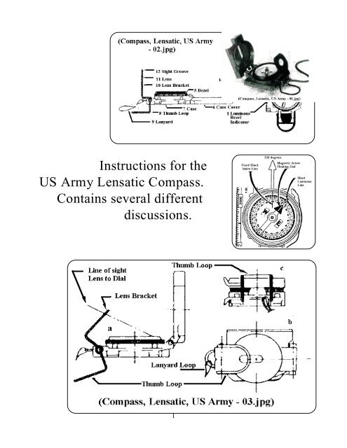
B. PARTS OF THE LENSATIC COMPASS <strong>Compass</strong>, <strong>Lensatic</strong>, <strong>US</strong> <strong>Army</strong>, closeup:<br />
2<br />
(From ano<strong>the</strong>r source)<br />
1. LUMINO<strong>US</strong> BEZEL INDICATOR: Used to mark a course direction during day or night.<br />
2. N – ARROW OF DIAL: locates magnetic North. The dial is divided into two scales;<br />
a. OUTER -(Black Printing) Graduated in Mils.<br />
6400 Mils to a Circle<br />
Distance Between Black Marks = 20 Mils<br />
Distance Between Black Numerals = 200 Mils<br />
N = 64 (6400) E = 16 (1600), S = 32 (3200), W = 48 (4800)
. INNER -(Red Printing) Graduated in Degrees<br />
360 Degrees to a Circle<br />
Distance Between Red Marks = 5 Degrees<br />
Distance Between Red Numerals = 20 Degrees<br />
N = 0, E = 90, S = 180, W = 270 Degrees<br />
3. FIVE -INCH RULED SCALE (120 MILLIMETERS): Graduated at a ratio of 1:50,000. Distance on<br />
a 1:50,000 scale map can be measured (with <strong>the</strong> straight edge) up to 6000 meters 3.7 miles. The<br />
straight edge is useful <strong>for</strong> measuring distances, orienting a map and aligning bearings.<br />
Note: The map scale index is usually found in <strong>the</strong> marginal in<strong>for</strong>mation: However, <strong>the</strong><br />
corresponding ground distances of some commonly used map scales are shown below:<br />
SCALE ON MAP DISTANCE OVER GROUND<br />
1:10.560 6" 1 MILE<br />
1:25.000 1" APPROXIMATELY 2000 FT<br />
2.5" 1 MILE<br />
4 CM 1 KM<br />
1:31,680 2" 1 MILE<br />
1:50.000 1.25" 1 MILE<br />
2 CM 1 KM<br />
Numbers such as: (12), are shown in <strong>the</strong> picture (<strong>Compass</strong>, <strong>Lensatic</strong>, <strong>US</strong> <strong>Army</strong> - 02.jpg)<br />
4. SIGHT WIRE: Used (along with <strong>the</strong> sight groove (12) of <strong>the</strong> lens bracket (10) to set a course over<br />
<strong>the</strong> ground; or determine an azimuth (bearing, direction) by sighting on prominent terrain features and<br />
reading <strong>the</strong> compass dial through <strong>the</strong> lens (11).<br />
5. BEZEL: <strong>Contains</strong> <strong>the</strong> luminous bezel indicator (1). Has a serrated edge and rotates with a distinct<br />
clicking action. Each click moves <strong>the</strong> luminous bezel indicator over a 3 degree arc.<br />
6. CASE COVER: Closes to protect <strong>the</strong> compass and reduce carrying size. When opened wide (<strong>Compass</strong>,<br />
<strong>Lensatic</strong>, <strong>US</strong> <strong>Army</strong> - 02.jpg, left side) it can be used as a straight edge or ruler. When perpendicular as<br />
in (<strong>Compass</strong>, <strong>Lensatic</strong>, <strong>US</strong> <strong>Army</strong> - 03.jpg, a ), <strong>the</strong> SIGHT WIRE (4) is used to set course.<br />
7. CASE: <strong>Contains</strong> and protects <strong>the</strong> dial assembly.<br />
8. THUMB-LOOP: Locks <strong>the</strong> compass in <strong>the</strong> closed position (<strong>Compass</strong>, <strong>Lensatic</strong>, <strong>US</strong> <strong>Army</strong><br />
- 03.jpg, b, c ) When opened as (<strong>Compass</strong>, <strong>Lensatic</strong>, <strong>US</strong> <strong>Army</strong> - 03.jpg, a ) It facilitates holding <strong>the</strong><br />
compass to a set course to determine an azimuth. (<strong>Compass</strong>, <strong>Lensatic</strong>, <strong>US</strong> <strong>Army</strong> - 04.jpg)<br />
3
9. LANYARD: A loop of braided nylon cord to secure <strong>the</strong> compass around <strong>the</strong> neck and ease access to it<br />
when carried in a shirt pocket.<br />
10. LENS BRACKET: When pushed all <strong>the</strong> way down it lifts <strong>the</strong> dial off <strong>the</strong> pivot. When <strong>the</strong> compass is<br />
not being used, it is important to raise <strong>the</strong> dial in order to prevent damage to <strong>the</strong> pivot (point on which<br />
<strong>the</strong> dial balances).<br />
11. LENS: High quality magnifier (about 2.5 inch focal length) to read <strong>the</strong> compass dial when positioned<br />
about 30 degrees off perpendicular. Handle carefully with clean tissue. Caution: close lens bracket<br />
against bezel glass be<strong>for</strong>e closing hinged cover. (Note that this lens is made of plastic, and not glass.)<br />
12. SIGHT GROOVE: Used to set a course over <strong>the</strong> ground to determine an azimuth when it is used<br />
along with <strong>the</strong> sight wire (4), <strong>the</strong> index line (13) and <strong>the</strong> dial (2).<br />
13. INDEX LINE: Black line etched on <strong>the</strong> crystal over <strong>the</strong> dial. Used to read an azimuth.<br />
C. SIGHTING AN AZIMUTH (Taking a <strong>Compass</strong> Bearing)<br />
1. Open <strong>the</strong> lensatic compass as shown in (<strong>Compass</strong>, <strong>Lensatic</strong>, <strong>US</strong> <strong>Army</strong> - 03.jpg, left side).<br />
a. Cover should be perpendicular (90 degrees) to <strong>the</strong> case.<br />
b. Lens bracket should be tilted about 30 degrees from perpendicular. Be sure <strong>the</strong> dial floats freely.<br />
2. Sight <strong>the</strong> <strong>Lensatic</strong> <strong>Compass</strong>.<br />
a. Insert thumb through thumb loop (<strong>Compass</strong>, <strong>Lensatic</strong>, <strong>US</strong> <strong>Army</strong> - 04.jpg)<br />
b. Hold <strong>the</strong> compass level on <strong>the</strong> plat<strong>for</strong>m <strong>for</strong>med by <strong>the</strong> thumb and bent index finger (<strong>Compass</strong>,<br />
<strong>Lensatic</strong>, <strong>US</strong> <strong>Army</strong> - 04.jpg) .<br />
c. Raise <strong>the</strong> compass to eye level (<strong>Compass</strong>, <strong>Lensatic</strong>, <strong>US</strong> <strong>Army</strong> - 04.jpg)<br />
d. Align <strong>the</strong> center of <strong>the</strong> sighting groove in <strong>the</strong> lens bracket with <strong>the</strong> sight wire and a distant object<br />
- dotted line i (<strong>Compass</strong>, <strong>Lensatic</strong>, <strong>US</strong> <strong>Army</strong> - 04.jpg)<br />
3. Without moving your head, or <strong>the</strong> compass, read <strong>the</strong> azimuth through <strong>the</strong> lens of <strong>the</strong> lens bracket,<br />
-dotted line ii (<strong>Compass</strong>, <strong>Lensatic</strong>, <strong>US</strong> <strong>Army</strong> - 04.jpg) The azimuth, in degrees, is <strong>the</strong> red number on<br />
<strong>the</strong> dial lying directly under <strong>the</strong> black index line of <strong>the</strong> compass crystal. The azimuth, in mils is <strong>the</strong><br />
black number on <strong>the</strong> outer perimeter of <strong>the</strong> dial.<br />
D. TO SET A COURSE (FOLLOW A BEARING)<br />
1ST METHOD<br />
a. With <strong>the</strong> lensatic compass opened wide ((<strong>Compass</strong>, <strong>Lensatic</strong>, <strong>US</strong> <strong>Army</strong> - 02.jpg -b ) and held level,<br />
turn it horizontally until <strong>the</strong> azimuth is directly under <strong>the</strong> black index line. Example: you want to<br />
follow a bearing of 120 degrees. Position <strong>the</strong> 120 degree mark under <strong>the</strong> index line.<br />
b. Holding <strong>the</strong> lensatic compass in this position, rotate <strong>the</strong> bezel until <strong>the</strong> luminous indicator is over <strong>the</strong><br />
N arrow of <strong>the</strong> dial. The direction indicated by <strong>the</strong> open compass is <strong>the</strong> desired course. As long as <strong>the</strong><br />
bezel is not rotated, <strong>the</strong> course can be checked by turning <strong>the</strong> open compass so that <strong>the</strong> luminous bezel<br />
indicator is directly over <strong>the</strong> n arrow of <strong>the</strong> dial.<br />
4
2ND METHOD<br />
a. Turn <strong>the</strong> fully opened lensatic compass and rotate <strong>the</strong> bezel to align <strong>the</strong> luminous bezel indicator, <strong>the</strong><br />
black index line and <strong>the</strong> N arrow of <strong>the</strong> dial.<br />
b. Subtract <strong>the</strong> number of degrees, in your desired azimuth, from 360 degrees.<br />
c. Keeping <strong>the</strong> N arrow under <strong>the</strong> index line, turn <strong>the</strong> luminous bezel indicator to this result.<br />
EXAMPLE: You want to follow a course of 120 degrees. Subtract 120 degrees from 360 degrees,<br />
leaving 240 degrees. Keeping <strong>the</strong> N arrow under <strong>the</strong> index line, rotate <strong>the</strong> bezel until <strong>the</strong> luminous<br />
bezel indicator is over 240 degrees.<br />
d. Turn <strong>the</strong> compass until <strong>the</strong> N arrow lies directly under <strong>the</strong> luminous bezel indicator. The direction<br />
indicated by <strong>the</strong> open compass cover p31nts <strong>the</strong> desired course.<br />
3RD METHOD<br />
a. Turn <strong>the</strong> fully opened compass and rotate <strong>the</strong> bezel to align <strong>the</strong> lights in <strong>the</strong> cover with <strong>the</strong> luminous<br />
bezel indicator.<br />
b. Rotate <strong>the</strong> bezel counterclockwise to <strong>the</strong> azimuth desired.<br />
Each distinct click of <strong>the</strong> bezel represents 3 degrees.<br />
Example: You want to follow a course of 120 degrees. Divide 120 by 3. The result is 40; <strong>the</strong>re<strong>for</strong>e<br />
rotate <strong>the</strong> bezel 40 clicks counter-clockwise.<br />
c. Turn <strong>the</strong> compass until <strong>the</strong> N arrow lies directly under <strong>the</strong> luminous bezel indicator. The direction,<br />
indicated by <strong>the</strong> lights in <strong>the</strong> compass cover, points <strong>the</strong> desired course.<br />
E. PROCEEDING ALONG AN AZIMUTH<br />
1. With your lensatic compass pointing along a desired azimuth. Select an easily identified object that is<br />
in line with <strong>the</strong> sighting groove of <strong>the</strong> lens bracket and <strong>the</strong> sight wire (<strong>Compass</strong>, <strong>Lensatic</strong>, <strong>US</strong> <strong>Army</strong> -<br />
04.jpg). This 'steering mark' should be distinct from surroundings. It should be visible at all times<br />
along <strong>the</strong> route and should be identifiable when reached. The greater <strong>the</strong> distance to a steering mark,<br />
<strong>the</strong> fewer steering marks you will need to reach your goal.<br />
2. If your steering mark is lost to view, stop, re-sight and select a new steering mark immediately.<br />
3. If a good steering mark is not in line with your desired azimuth, select an alternative steering mark off<br />
to <strong>the</strong> side.<br />
5
a. Estimate <strong>the</strong> distance <strong>the</strong> steering mark is to <strong>the</strong> side of <strong>the</strong> desired course. (160 degrees, 2840 mils).<br />
Alternate is 167 degrees, 2970 mils.<br />
b. Head <strong>for</strong> <strong>the</strong> point on <strong>the</strong> traveled path that is beside <strong>the</strong> alternative steering mark. At this position<br />
sight a back azimuth to your old steering mark. (A back azimuth is 180 degrees away from a traveled<br />
azimuth. If <strong>the</strong> traveled azimuth is less than 180 degrees (3200 mils), add 180 degrees and if <strong>the</strong><br />
traveled azimuth is more than 180 degrees, subtract 180 degrees. In (<strong>Compass</strong>, <strong>Lensatic</strong>, <strong>US</strong> <strong>Army</strong> -<br />
04b.jpg), <strong>the</strong> back azimuth is 344 degrees (6110 mils).<br />
c. Correct back azimuth of original course is 340 degrees which is 180 degrees plus <strong>the</strong> traveled azimuth<br />
of 160 degrees; <strong>the</strong>re<strong>for</strong>e, you will have to move perpendicularly until you can sight a back azimuth<br />
of 340 degrees (6040 mils) when sighting your old steering mark. You are now back on your<br />
correct, originally desired course.<br />
4. In darkness, chose steering marks that are closer toge<strong>the</strong>r and have a distinct silhouette against <strong>the</strong> sky.<br />
5. Military experience advises against frequent unnecessary sightings and walking while watching <strong>the</strong><br />
compass; however, when steering marks cannot be used, <strong>the</strong> fully opened compass pointing <strong>the</strong><br />
travel direction should be held in front of <strong>the</strong> chest. (See H. -night-time use).<br />
6
F. ADJ<strong>US</strong>TING MAP BEARINGS FOR VARIATION - Setting <strong>the</strong> map.<br />
If you are unfamiliar with declination, review 3, 4 of K. (Definitions).<br />
1ST METHOD - With magnetic N (MN) arrow shown<br />
(see declination diagram, “<strong>Compass</strong>, <strong>Lensatic</strong>, <strong>US</strong><br />
<strong>Army</strong> - 06.jpg” , section K ).<br />
a. Place <strong>the</strong> map flat, away from metallic objects.<br />
b. Place <strong>the</strong> fully opened lensatic compass on map<br />
with <strong>the</strong> edge of <strong>the</strong> scale alongside <strong>the</strong><br />
magnetic N arrow of <strong>the</strong> declination diagram.<br />
Adjust <strong>the</strong> map (with <strong>the</strong> compass on it) so that<br />
<strong>the</strong> compass cover points to magnetic North<br />
(N arrow of compass is pointing directly to<br />
index line).<br />
The map is now oriented to <strong>the</strong> terrain.<br />
[Picture at right from ano<strong>the</strong>r source.]<br />
[Simplistic picture shown again later.<br />
MAP ORIENTATION BY COMPASS<br />
Lay <strong>the</strong> map down on a flat level surface,<br />
<strong>the</strong>n align <strong>the</strong> north indicating line on <strong>the</strong><br />
map with magnetic North of <strong>the</strong> compass.<br />
The map is now oriented.]<br />
2ND METHOD - With no magnetic N arrow shown on <strong>the</strong> map.<br />
a. Find <strong>the</strong> magnetic declination in <strong>the</strong> map margin. This will state <strong>the</strong> deviation to be so many degrees<br />
E or W of true North. Example: Magnetic declination 11 degrees W means <strong>the</strong> N arrow of <strong>the</strong> lensatic<br />
compass will point 11 degrees West of true North.<br />
b. Place <strong>the</strong> fully opened lensatic compass on <strong>the</strong> map with <strong>the</strong> edge of <strong>the</strong> scale alongside a North-South<br />
Meridian (longitudinal line, grid line). The compass cover should be pointing toward <strong>the</strong> top of <strong>the</strong><br />
map.<br />
c. Turn <strong>the</strong> map and <strong>the</strong> compass toge<strong>the</strong>r until <strong>the</strong> N arrow of <strong>the</strong> dial is <strong>the</strong> same number of degrees E<br />
or W of <strong>the</strong> index line as stated on <strong>the</strong> map. The map is now oriented to <strong>the</strong> terrain.<br />
3RD METHOD - When your position on <strong>the</strong> map is known.<br />
a. Select a prominent terrain feature on <strong>the</strong> ground.<br />
b. Sight an azimuth from your position on <strong>the</strong> ground to <strong>the</strong> selected terrain feature.<br />
c. Align <strong>the</strong> fully opened compass on <strong>the</strong> map so that <strong>the</strong> scale edge runs through <strong>the</strong> selected terrain<br />
feature and your known position.<br />
d. Turn <strong>the</strong> map and compass toge<strong>the</strong>r until <strong>the</strong> azimuth sighted (in b, above), lies under <strong>the</strong> index line.<br />
The map is now oriented to <strong>the</strong> terrain.<br />
7
---------------------------------------------------------------------------------------------------------------------------------<br />
The following pictures, from ano<strong>the</strong>r source, are included here to help you along.<br />
Below, You are where <strong>the</strong> two rays intersect each o<strong>the</strong>r.<br />
8<br />
Above, A magnetic azimuth of any object is <strong>the</strong><br />
compass reading of a direct line across <strong>the</strong> center of<br />
<strong>the</strong> compass to <strong>the</strong> object.<br />
When taking <strong>the</strong> azimuth reading, set sight on<br />
object through <strong>the</strong> slot and wire, <strong>the</strong>n read <strong>the</strong><br />
degree scale through lens.<br />
---------------------------------------------------------------------------------------------------------------------------------<br />
G. LOCATING YOUR POSITION ON A MAP BY MEANS OF INTERSECTING AZIMUTHS<br />
1. Orient <strong>the</strong> map to <strong>the</strong> terrain.<br />
2. Sight an azimuth to any visible terrain feature that appears on <strong>the</strong> map.<br />
3. Place <strong>the</strong> fully opened lensatic compass on <strong>the</strong> map with <strong>the</strong> ruled edge running through <strong>the</strong> terrain<br />
feature and with <strong>the</strong> compass reading me same as <strong>the</strong> azimuth sighted. Draw a line along <strong>the</strong> ruled<br />
edge<br />
4. Pick ano<strong>the</strong>r visible terrain feature and sight its azimuth. For greater accuracy <strong>the</strong> two lines should be<br />
approximately right angles.<br />
5. Repeat step 3.<br />
6. The point of intersection accurately locates your position on me map.<br />
7. From here you can determine <strong>the</strong> azimuth or bearing to any terrain feature shown on <strong>the</strong> map as long<br />
as your map is oriented.<br />
Keep reading, I have included o<strong>the</strong>r versions of how to use this compass in later pages.<br />
The material repeats, so you can finally get it. People learn better by studying several versions.
H. NIGHT-TIME <strong>US</strong>E:<br />
1. Try to determine a course (azimuth) to be followed while <strong>the</strong>re is still<br />
light.<br />
2. To set a course, follow instructions under :<br />
F. ADJ<strong>US</strong>TING MAP VARIATIONS FOR VARIATION<br />
- 3RD METHOD - d.<br />
3. With your course determined, hold <strong>the</strong> lensatic compass open and<br />
level in both hands, with <strong>the</strong> index fingers of <strong>the</strong> right hand along <strong>the</strong> side of <strong>the</strong> compass.<br />
Position <strong>the</strong> compass approximately halfway between <strong>the</strong> chin and <strong>the</strong> belt, keeping <strong>the</strong> n arrow under<br />
<strong>the</strong> luminous bezel indicator.<br />
5. Proceed <strong>for</strong>ward in <strong>the</strong> direction that <strong>the</strong> index finger is pointed.<br />
I. INDUCTION DAMPING:<br />
The lensatic compass is induction damped verses. Liquid damped instruments are subject to<br />
leaking and eventual failure. Induction damping allows <strong>the</strong> dial to seek magnetic North and come to a<br />
complete rest in much less time than a unit without induction damping. It is a velocity dependent <strong>for</strong>ce;<br />
that is, as <strong>the</strong> speed of <strong>the</strong> oscillation of <strong>the</strong> dial comes to rest, <strong>the</strong> damping <strong>for</strong>ce is zero.<br />
J. GENERAL - THE LENSATIC COMPASS.<br />
F Has a dial balanced on a precision made syn<strong>the</strong>tic sapphire jeweled bearing.<br />
F Is induction damped by means of a copper damping shell so that dial comes to rest within six seconds.<br />
F Has a rubber cup sealing <strong>the</strong> copper damping shell, making he compass waterproof.<br />
F Is tested to operate at temperature ranges from -50 degrees F. to +160 degrees F.<br />
F Is made to meet rigid U.S. Military Specifications.<br />
F Has been used <strong>for</strong> many years by Armed Forces around <strong>the</strong> world.<br />
F Has been judged to be <strong>the</strong> most accurate, dependable, rugged and versatile compass that is available.<br />
F Because of its compact size, light weight and accuracy, is ideally suited <strong>for</strong> boating, camping,<br />
cross-country skiing, fishing, hunting and orienteering. Important - readings should never be taken<br />
near visible masses of iron or electrical circuits, because of <strong>the</strong>ir effects on <strong>the</strong> compass<br />
magnet. The following are suggested as approximate safe distances to insure proper<br />
functioning of <strong>the</strong> compass.<br />
a. High tension power lines ............................... 55 meters (60 yards)<br />
b. Car, truck, camper ......................................... 18 meters (20 yards)<br />
c. Telephone lines, wire fences ......................... 10 meters(11 yards)<br />
d. Shotgun, rifle, metal boxes. Etc. ................... 0.5 meters(1.5 feet)<br />
9
HOW TO <strong>US</strong>E THE ENGINEER COMPASS<br />
(<strong>Lensatic</strong> compass) This is from <strong>the</strong> little paper that came with my five-dollar compass.<br />
It is included in case you did not follow <strong>the</strong> previous pages.<br />
Finding real position on Map by compass<br />
Take two azimuth bearings on separate characteristic points visible on <strong>the</strong> terrain and indicated on <strong>the</strong><br />
map. Then on your oriented map, take <strong>the</strong> angle degree reading according to (a), and <strong>the</strong>n draw two rays<br />
from each of <strong>the</strong> above points according to <strong>the</strong> angle reading, where <strong>the</strong> two rays intersect is your present<br />
location.<br />
Below - You are where <strong>the</strong> two rays intersect each o<strong>the</strong>r.<br />
[Though both compasses are used <strong>the</strong> same<br />
way, I am told that <strong>the</strong> <strong>US</strong> <strong>Army</strong> <strong>Lensatic</strong> compass<br />
will give you readings accurate to three degrees.<br />
Some can employ it to within one degree.<br />
The best hoped <strong>for</strong> in <strong>the</strong> above mentioned<br />
five-dollar compass is about five degrees. Significant<br />
<strong>for</strong> long distances.]<br />
10<br />
Map Orientation by <strong>Compass</strong><br />
Lay <strong>the</strong> map down on a flat level surface, <strong>the</strong>n<br />
align <strong>the</strong> north indicating line on <strong>the</strong> map with<br />
magnetic north of <strong>the</strong> compass. The map is now<br />
oriented.<br />
Magnetic Azimuth<br />
A magnetic azimuth of any object is <strong>the</strong> compass<br />
reading of a direct line across <strong>the</strong> center of <strong>the</strong><br />
compass to <strong>the</strong> object.<br />
When taking <strong>the</strong> azimuth reading, set sight on object<br />
through <strong>the</strong> slot and wire, <strong>the</strong>n read <strong>the</strong> degree scale<br />
through lens.
Walking in darkness & dense fog and through rough terrain<br />
The line on <strong>the</strong> glass bezel is <strong>for</strong> quick walking through rough terrain : - (on <strong>the</strong> surface of <strong>the</strong><br />
glass are found two lines, long and short. They <strong>for</strong>m an angle of 45 degrees with each o<strong>the</strong>r. ) First, turn<br />
your compass to face True North, <strong>the</strong>n rotate <strong>the</strong> luminous line on your glass bezel to whatever number of<br />
degrees you wish to walk; example - move bezel 20 notches till line is on 60 degrees <strong>the</strong> when compass is<br />
aligned with North. Now you may take a quick reading at any time. While you are walking, just turn your<br />
compass towards <strong>the</strong> Magnetic North and walk in <strong>the</strong> direction of <strong>the</strong> line on <strong>the</strong> bezel.<br />
Bezel rotates 360 degrees and is marked off in 3 degree notches <strong>for</strong> easy computation. (A glass<br />
plate may be turned around to produce a scratching sound. Each sound denotes <strong>the</strong> rotation by 3 degrees. )<br />
---------------------------------------------------------------------------------------------------------------------------------<br />
Map & <strong>Compass</strong>; Using; The Leisurely Backpacker http://www.leisurelybackpacker.com/a_compass.htm<br />
This version is an easy -to -read one from <strong>the</strong> internet.<br />
The Leisurely Backpacker - Using Map & <strong>Compass</strong><br />
I'm including this brief overview <strong>for</strong> people who are unfamiliar with map reading and <strong>the</strong> use of a<br />
compass. Many a hiker has found himself in <strong>the</strong> woods with a compass or map, or both, and when unsure<br />
of <strong>the</strong>ir location, been struck by <strong>the</strong> realization that even though <strong>the</strong>y have <strong>the</strong> appropriate navigational<br />
tools, <strong>the</strong>y do not have <strong>the</strong> knowledge to use <strong>the</strong>m. This overview should be considered just that, an<br />
overview. For a more complete explanation of using a map and compass in <strong>the</strong> wilderness, I suggest<br />
reading June Fleming's excellent book, Staying Found.<br />
Topographic Maps<br />
There are several kinds of maps available on <strong>the</strong> marketplace; too many to list here. The type of<br />
map I'm going to discuss here is <strong>the</strong> topographic map. A topographic map uses contour lines to portray <strong>the</strong><br />
shape and elevation of <strong>the</strong> land. These lines are <strong>the</strong> twisted, curved brown lines that connect points of<br />
equal elevation on <strong>the</strong> map. The contour interval is <strong>the</strong> set distance between contour lines on a given map,<br />
measures in feet or meters. This interval can be found near <strong>the</strong> map's scale, which is usually located in <strong>the</strong><br />
map legend. These contour lines make it possible <strong>for</strong> a topographic map to render <strong>the</strong> tree-dimensional<br />
ups and downs of <strong>the</strong> terrain on <strong>the</strong> two-dimensional surface of <strong>the</strong> map.<br />
Topographic maps show both natural and man-made (cultural) features. They use symbols, lines<br />
and colors to portray map features. Topo maps show areas shaded in various colors to represent land<br />
cover. Areas on a topo map that are shaded green represent vegetation, usually wooded cover (trees) or<br />
brush. Areas of blue and blue lines indicate bodies of water. Areas that are white are usually areas with<br />
little or no vegetation, such as desert or rocky alpine areas. Wilderness, national park, and national <strong>for</strong>est<br />
boundaries consist of black, dashed, dotted lines tinted with green, brown or gray shades. Consult <strong>the</strong> map<br />
legend <strong>for</strong> specific tints. Features that are denoted by lines are: topographic contours, shown in brown,<br />
streams, rivers and lakes in blue, and roads, trails, and boundary lines, usually in black. Some lines are<br />
solid, some are dashed, and <strong>the</strong> width and darkness of lines often vary in order to distinguish features from<br />
one ano<strong>the</strong>r.<br />
The <strong>Compass</strong><br />
It is important to know how to use a compass if you plan on venturing into <strong>the</strong> backcountry. First,<br />
a quick explanation on what a compass is. A map compass has a magnetized needle in a liquid-filled vial<br />
that can be rotated relative to it's clear base. Around this vial is an azimuth ring that indicates 0-360<br />
degrees. Declination (explained below) can be accounted <strong>for</strong> by offsetting <strong>the</strong> orienting arrow <strong>the</strong><br />
appropriate number of degrees east or west. Map compasses can be used <strong>for</strong> navigating precisely with or<br />
without a map.<br />
The magnetic needle on a compass points to magnetic north. The dial, orienting arrow, and<br />
sighting line are used to help you find East, West, South, and <strong>the</strong> points in between.<br />
11
Declination<br />
Un<strong>for</strong>tunately, true north and magnetic<br />
north are not located at <strong>the</strong> same place. A compass<br />
needle points to magnetic north; <strong>the</strong> number of<br />
degrees East or West that magnetic north and true<br />
north are separated by is known as declination.<br />
Many compasses have built-in declination<br />
adjustments; o<strong>the</strong>rs do not. For accurate compass<br />
readings, it is necessary to account <strong>for</strong> declination.<br />
The isogonic chart at right roughly shows<br />
declination <strong>for</strong> <strong>the</strong> United States.<br />
If, <strong>for</strong> example, you are in <strong>the</strong> White Mountains of New Hampshire, you will have a west<br />
declination of about 16 degrees, meaning that magnetic north is 16 degrees west of true north. By aligning<br />
your magnetic needle 16 degrees west of true north (360 degrees minus 16 degrees, or 344 degrees), <strong>the</strong><br />
azimuth ring will <strong>the</strong>n be correctly oriented <strong>for</strong> true north. For compasses that do not have built-in<br />
declination adjustments, it is common practice to place a small piece of tape at <strong>the</strong> declination point of <strong>the</strong><br />
azimuth ring. In o<strong>the</strong>r words, if you are in an area with a westerly declination, align <strong>the</strong> magnetic end of<br />
your compass needle to 360 minus <strong>the</strong> declination. If, however, you are in an area with an easterly<br />
declination, align <strong>the</strong> magnetic end of your compass needle to <strong>the</strong> number (degree) on your dial that is <strong>the</strong><br />
declination.<br />
Taking a Bearing<br />
A bearing is a degree reading taken from your position to ano<strong>the</strong>r object. If, <strong>for</strong> example, a<br />
mountain peak was directly east of your position, <strong>the</strong> bearing of <strong>the</strong> mountain would be 90 degrees. If <strong>the</strong><br />
peak was directly south, its bearing would be 180 degrees, and if <strong>the</strong> peak was directly west, 270 degrees.<br />
To take a bearing, hold <strong>the</strong> compass level in front of you. With <strong>the</strong> sighting line on <strong>the</strong> base of <strong>the</strong><br />
compass pointing straight at <strong>the</strong> object you are taking a bearing on, turn <strong>the</strong> dial until <strong>the</strong> magnetic needle<br />
is lined up with your declination tape (or <strong>the</strong> orienting arrow, if your compass has a built-in adjustment <strong>for</strong><br />
declination). The degree reading indicated at <strong>the</strong> sighting line is <strong>the</strong> bearing to your object.<br />
Using Map & <strong>Compass</strong> <strong>for</strong> Navigation<br />
I'd like to explain how to pinpoint your location while you are backcountry. You can locate<br />
yourself by <strong>the</strong> intersection of lines. If you are already on a marked trail, or along a stream, or on a<br />
ridgeline, <strong>the</strong>n you already have one line, and need only one more to determine your location on <strong>the</strong> map.<br />
If you aren't on a known line, <strong>the</strong>n you'll need two lines to determine your location. To get <strong>the</strong> line(s) you<br />
need, take bearings on identifiable landmarks. When you plot <strong>the</strong>se bearings on your map, <strong>the</strong>ir point of<br />
intersection indicates your location.<br />
First, use your compass to orient your map and place <strong>the</strong> map on a flat surface (<strong>the</strong> ground) and<br />
anchor <strong>the</strong> corners with rocks. Then, take a bearing on a landmark some distance away that is also<br />
identified on <strong>the</strong> map. Next, set <strong>the</strong> compass on <strong>the</strong> map with a front corner of <strong>the</strong> baseplate aligned with<br />
<strong>the</strong> landmark. Now rotate <strong>the</strong> compass, keeping <strong>the</strong> pivot point on <strong>the</strong> landmark, until <strong>the</strong> magnetic needle<br />
is again aligned with your declination tape. Draw a line along <strong>the</strong> edge of <strong>the</strong> compass base, from <strong>the</strong><br />
pivot point back. Repeat this procedure with ano<strong>the</strong>r landmark; <strong>the</strong> intersection of <strong>the</strong> lines on <strong>the</strong> map<br />
indicate your location. Copyright © 1996, David Lister<br />
12
<strong>Compass</strong>, Use of, Map Reading, <strong>Army</strong> way http://www.geocities.com/Pentagon/Base/1764/<br />
Using Map and <strong>Compass</strong><br />
<strong>the</strong> <strong>Army</strong> Way<br />
Tools (Materials needed <strong>for</strong> students to complete project):<br />
<strong>Lensatic</strong> compass (one <strong>for</strong> each pair of students)<br />
Protractor (one <strong>for</strong> each student)<br />
Topographical map of location <strong>for</strong> Student Activity four<br />
(one <strong>for</strong> each pair of students)<br />
Paper <strong>for</strong> computing back azimuths<br />
Sharp pencil (.05 lead) <strong>for</strong> plotting azimuths<br />
Classroom with overhead projector<br />
Outside area with 10 known points<br />
(identifiable on a map and over 1000 meters from working area)<br />
Lesson 1: Determining magnetic azimuths using a lensatic compass. The center hold<br />
technique is <strong>the</strong> fastest and easiest way to measure a magnetic azimuth.<br />
4. Once you are pointing at <strong>the</strong> object, look down and read<br />
<strong>the</strong> azimuth from beneath <strong>the</strong> fixed black index line. The<br />
second diagram at right (Figure 2) illustrates a magnetic<br />
azimuth of 320 degrees.<br />
You must measure at least two well defined distant<br />
locations that can be pinpointed on <strong>the</strong> map. Two is what<br />
we will cover in this lesson but three would be more<br />
accurate. To determine <strong>the</strong> second azimuth repeat steps 2<br />
to 4 on ano<strong>the</strong>r well defined distant location.<br />
Be sure you are away from power lines, vehicles or o<strong>the</strong>r<br />
metal objects when using a compass, <strong>the</strong>se objects will<br />
affect its per<strong>for</strong>mance!<br />
1. Make sure <strong>the</strong> needle on <strong>the</strong> lensatic compass is floating freely.<br />
2. Hold <strong>the</strong> compass between <strong>the</strong> <strong>for</strong>efingers and thumbs of both hands and<br />
pull your elbows down to your sides (Figure 1). This action will place <strong>the</strong><br />
compass between your chin and waist.<br />
3. To measure an azimuth, simply turn your entire body toward <strong>the</strong> object,<br />
pointing <strong>the</strong> zero or index mark directly at <strong>the</strong> distant known location.<br />
13
diagram is <strong>the</strong> right of <strong>the</strong> grid North line<br />
(marked with an E in <strong>the</strong> G-M angle)<br />
add <strong>the</strong> G-M angle to <strong>the</strong> magnetic<br />
azimuth. If <strong>the</strong> result of this addition is<br />
larger than 360 degrees you must<br />
subtract 360 degrees to determine <strong>the</strong><br />
grid azimuth.<br />
If <strong>the</strong> magnetic North arrow is to <strong>the</strong> left of <strong>the</strong> grid North line (marked with a W in <strong>the</strong> G-M angle)<br />
subtract <strong>the</strong> G-M angle to determine<br />
<strong>the</strong> magnetic azimuth. If <strong>the</strong> result of<br />
this subtraction is a negative number<br />
you must add 360 degrees to determine<br />
<strong>the</strong> grid azimuth.<br />
The angular difference between grid<br />
and magnetic North is caused by <strong>the</strong><br />
attraction of <strong>the</strong> Earth's magnetic field.<br />
This field is found in Nor<strong>the</strong>rn<br />
Canada.<br />
14
Lesson 3: Convert grid azimuths to back azimuths<br />
You have done <strong>the</strong> first two of <strong>the</strong> four steps in locating yourself on a topographical map. You have<br />
located two distant known points. You have converted <strong>the</strong>ir magnetic direction to a grid (or map)<br />
direction. You know <strong>the</strong> direction to <strong>the</strong>m but not to your location. To determine your location you must<br />
compute <strong>the</strong> back direction. The back azimuth is determined by adding or subtracting 180 degrees to <strong>the</strong><br />
grid azimuth. This lesson will assist you in learning how to convert <strong>the</strong> grid azimuth to a back azimuth. In<br />
<strong>the</strong> fourth (last lesson) you will be able to plot <strong>the</strong> two back azimuths and determine your location. First<br />
you learn to convert grid azimuths to back azimuths.<br />
To determine back azimuths that are less than 180 degrees<br />
add 180 degrees.<br />
To determine back azimuths that are more than 180 degrees<br />
subtract 180 degrees.<br />
Examples:<br />
Grid azimuth = 107 degrees (add 180) 107 + 180 = 287 degrees<br />
Grid azimuth = 243 degrees (subtract 180) 243 - 180 = 063 degrees<br />
Lesson 4: Convert grid azimuths to back azimuths Plot back azimuths. Determine location on<br />
a topographical map<br />
You have done <strong>the</strong> first three of <strong>the</strong> four steps in locating yourself on a topographical map. You<br />
have located two distant known points. You have converted <strong>the</strong>ir magnetic direction to a grid (or map)<br />
direction. You know <strong>the</strong> direction to <strong>the</strong>m but not to your location. Now that you have learned to convert<br />
<strong>the</strong> grid azimuths to back azimuths you are ready to finish up. This lesson helps you understand how to<br />
plot <strong>the</strong> back azimuths. The two or three back azimuths will intersect at a location on <strong>the</strong> map. Where <strong>the</strong>y<br />
intersect is your location (X marks <strong>the</strong> spot).<br />
Orient <strong>the</strong> map toward <strong>the</strong> North using <strong>the</strong> compass.<br />
Identify two or three known distant locations on <strong>the</strong> ground and mark <strong>the</strong>m on <strong>the</strong> map.<br />
Measure <strong>the</strong> magnetic azimuth to <strong>the</strong> first of <strong>the</strong> two or three known positions from your location<br />
using a compass (lesson 1).<br />
Convert <strong>the</strong> magnetic azimuth to a grid azimuth (lesson 2).<br />
Convert <strong>the</strong> grid azimuth to a back azimuth (lesson 3).<br />
Using a protractor, draw <strong>the</strong> back azimuth on <strong>the</strong> map from <strong>the</strong> known distant position back toward your<br />
unknown position.<br />
Repeat <strong>the</strong> steps in blue <strong>for</strong> a second and optional third known distant position.<br />
The intersection of <strong>the</strong> lines is your location.<br />
K. DEFINITIONS Grid Lines<br />
15
1. AZIMUTH (bearing, direction) - A horizontal<br />
angle in respect to North (degrees, 6400 mils). It<br />
is read on <strong>the</strong> dial of <strong>the</strong> lensatic compass in<br />
ei<strong>the</strong>r degrees or mils, by <strong>the</strong> number directly<br />
under <strong>the</strong> black index line.<br />
Example: Azimuth of 90 degrees or 1600 mils<br />
(Read 16) is due East.<br />
2. COORDINATES The North / South and<br />
East / West lines on a Map (grid lines). Positions<br />
are determined on a map by intersecting<br />
coordinates. The lower left is <strong>the</strong> origin and<br />
coordinates are read to <strong>the</strong> right and <strong>the</strong>n up.<br />
3. NORTH Generally a topographical map (a<br />
map using contour lines to show elevation and make possible<br />
<strong>the</strong> identification of canyons, peaks, ridges and o<strong>the</strong>r terrain<br />
features) shows three North’s in <strong>the</strong> declination diagram.<br />
a. TRUE NORTH The actual position of <strong>the</strong> North Pole of<br />
<strong>the</strong> Earth's surface. It is <strong>the</strong> Nor<strong>the</strong>rly Point toward which <strong>the</strong><br />
Meridians (North, South or longitudinal lines) between <strong>the</strong><br />
Poles are drawn. Maps generally are oriented to true North.<br />
(Shown at left by a ray or line tipped with a star ).<br />
b. MAGNETIC NORTH An irregular and wavering<br />
magnetic <strong>for</strong>ce which tends to run generally Northward and<br />
Southward, causing a compass to point variously, depending<br />
on location. These magnetic 'Polar Areas' are more man 1000<br />
miles away from <strong>the</strong> North and South Poles and it is in <strong>the</strong>se<br />
directions that <strong>the</strong> compass magnet points.<br />
(Shown by a ray tipped with MN and / or a single barbed<br />
spear.)<br />
c. GRID NORTH The North indicated by <strong>the</strong> Map Meridians running longitudinally. Because of <strong>the</strong><br />
Earth's curvature, <strong>the</strong>se lines are often pulled a little away from <strong>the</strong> true Meridian in order to provide a<br />
straight line, rectangular layout of coordinates. (Shown above by a ray tipped with GN.)<br />
16
4. MAGNETIC DECLINATION The horizontal angle (difference in degrees) between Magnetic<br />
North and True North. The Magnetic Declination Angle varies from area to area and from time to time;<br />
generally about 1' (one minute) per year. (There are 60 minutes to one degree). The picture below<br />
shows an Isogonic Chart <strong>for</strong> <strong>the</strong> U.S. This chart is helpful to understand how Magnetic North readings<br />
will vary from True North <strong>for</strong> different parts of <strong>the</strong> country. This declination (variation, angular<br />
difference) will be shown in <strong>the</strong> Declination Diagram or stated in <strong>the</strong> marginal in<strong>for</strong>mation on your Map.<br />
A. Lines to <strong>the</strong> left of <strong>the</strong> Zero Declination Line on <strong>the</strong> Isogonic Chart are called Easterly Variation.<br />
The N Arrow of <strong>the</strong> lensatic compass will point East of True North.<br />
B. Lines to <strong>the</strong> right of <strong>the</strong> Zero Declination Line on <strong>the</strong> Isogonic Chart are called Westerly Variation.<br />
The N Arrow of <strong>the</strong> lensatic compass will point West of True North.<br />
C. When <strong>the</strong> lensatic compass is used with a map or in conjunction with a map bearing, an adjustment<br />
should be made to allow <strong>for</strong> <strong>the</strong> variation. This is not necessary <strong>for</strong> rough compass work. In areas where<br />
<strong>the</strong> variation is slight, or <strong>for</strong> maps that use Magnetic North to locate <strong>the</strong> longitudinal grid lines (such as<br />
some orienteering maps).<br />
17