Franklin Fueling Systems TSP-IGF4 Water Float - NSCEP | US EPA ...
Franklin Fueling Systems TSP-IGF4 Water Float - NSCEP | US EPA ...
Franklin Fueling Systems TSP-IGF4 Water Float - NSCEP | US EPA ...

Create successful ePaper yourself
Turn your PDF publications into a flip-book with our unique Google optimized e-Paper software.
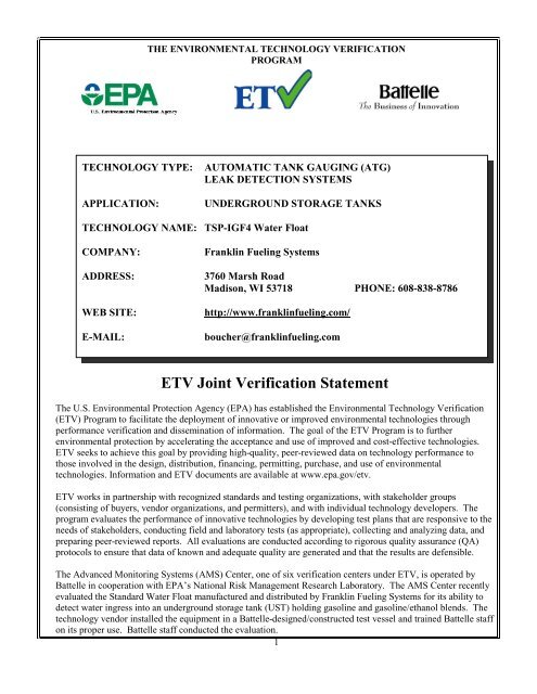
THE ENVIRONMENTAL TECHNOLOGY VERIFICATION<br />
PROGRAM<br />
TECHNOLOGY TYPE: AUTOMATIC TANK GAUGING (ATG)<br />
LEAK DETECTION SYSTEMS<br />
APPLICATION: UNDERGROUND STORAGE TANKS<br />
TECHNOLOGY NAME: <strong>TSP</strong>-<strong>IGF4</strong> <strong>Water</strong> <strong>Float</strong><br />
COMPANY: <strong>Franklin</strong> <strong>Fueling</strong> <strong>Systems</strong><br />
ADDRESS: 3760 Marsh Road<br />
Madison, WI 53718 PHONE: 608-838-8786<br />
WEB SITE: http://www.franklinfueling.com/<br />
E-MAIL: boucher@franklinfueling.com<br />
ETV Joint Verification Statement<br />
The U.S. Environmental Protection Agency (<strong>EPA</strong>) has established the Environmental Technology Verification<br />
(ETV) Program to facilitate the deployment of innovative or improved environmental technologies through<br />
performance verification and dissemination of information. The goal of the ETV Program is to further<br />
environmental protection by accelerating the acceptance and use of improved and cost-effective technologies.<br />
ETV seeks to achieve this goal by providing high-quality, peer-reviewed data on technology performance to<br />
those involved in the design, distribution, financing, permitting, purchase, and use of environmental<br />
technologies. Information and ETV documents are available at www.epa.gov/etv.<br />
ETV works in partnership with recognized standards and testing organizations, with stakeholder groups<br />
(consisting of buyers, vendor organizations, and permitters), and with individual technology developers. The<br />
program evaluates the performance of innovative technologies by developing test plans that are responsive to the<br />
needs of stakeholders, conducting field and laboratory tests (as appropriate), collecting and analyzing data, and<br />
preparing peer-reviewed reports. All evaluations are conducted according to rigorous quality assurance (QA)<br />
protocols to ensure that data of known and adequate quality are generated and that the results are defensible.<br />
The Advanced Monitoring <strong>Systems</strong> (AMS) Center, one of six verification centers under ETV, is operated by<br />
Battelle in cooperation with <strong>EPA</strong>’s National Risk Management Research Laboratory. The AMS Center recently<br />
evaluated the Standard <strong>Water</strong> <strong>Float</strong> manufactured and distributed by <strong>Franklin</strong> <strong>Fueling</strong> <strong>Systems</strong> for its ability to<br />
detect water ingress into an underground storage tank (<strong>US</strong>T) holding gasoline and gasoline/ethanol blends. The<br />
technology vendor installed the equipment in a Battelle-designed/constructed test vessel and trained Battelle staff<br />
on its proper use. Battelle staff conducted the evaluation.<br />
1
VERIFICATION TEST DESCRIPTION<br />
Testing was performed between September 13 and September 30, 2011. The verification test was designed to<br />
evaluate the functionality of the ATG systems when in ethanol-blended fuel service. The test was performed in<br />
the interior of an existing research building (JS-20) at Battelle’s West Jefferson, OH south campus. The building<br />
interior and the exterior area surrounding the building were modified to accommodate a specially-fabricated test<br />
vessel and support items. The test vessel was fabricated from a 6-ft diameter piece of a fiberglass storage tank<br />
shell that was fitted with glass ends to allow visual observation of the conditions within the vessel during testing.<br />
Exterior storage facilities were made available for fuel storage and waste storage.<br />
The characteristics of independent variables were selected and established during the runs to determine the<br />
response of the dependent variables. Performance parameters were evaluated based on the responses of the<br />
dependent variables and used to characterize the functionality of the ATG system. The water ingress tests were<br />
focused on the mixing method of water addition into the test vessel. Three test designs were incorporated into the<br />
evaluation:<br />
• A continuous water ingress test consisting of two parts:<br />
• Determination of minimum detection height;<br />
• Determination of smallest detectable incremental change in height; and<br />
• A quick water dump followed by a fuel dump.<br />
In the first test, a continuous stream of water was introduced into the field test vessel to produce a splash on the<br />
surface of the fuel or to not produce a splash by trickling the water along the surface of the fuel filler riser pipe to<br />
slowly meet the surface of the fuel. The independent variables and levels for the continuous water ingress test<br />
were:<br />
• Fuel ethanol content (three levels): E0 (no ethanol), E15 (15% ethanol), and flex fuel (up to 85% ethanol);<br />
• <strong>Water</strong> ingress method/rate (two levels): with splash and without splash; and<br />
• Fuel height (two levels): 25% and 65% full.<br />
The water ingress method/rate was selected to establish conditions that impact the degree of mixing that occurs in<br />
a tank using the three ethanol blends. The rate was established to accumulate enough water to generate a<br />
technology response within 1 hour. If a response was not observed in 3 hours, the run was terminated.<br />
Introducing water with a splash was accomplished by positioning a water tube such that water droplets would<br />
free-fall to the fuel surface below. The test condition was maintained until a response in the water detection<br />
technology was observed, or terminated after 3 hours if there was no response. Introducing water without a<br />
splash was accomplished by positioning the water tube such that surface tension allowed the water to flow along<br />
the outside of the fuel filler riser pipe with minimal agitation to the surface of the fuel. The test condition was<br />
maintained until a response in the water detection technology was observed, or terminated after 3 hours if there<br />
was no response.<br />
Two fuel height levels were specified to establish different splash mixing regimes and diffusion columns. The<br />
lower fuel height yielded the greater splash mixing potential, but the shorter diffusion columns through which the<br />
water could flow. Conversely, the higher fuel height yielded the lower splash mixing potential, but the higher<br />
diffusion column. The fill heights were established to ± 10% of the target height of either 25% or 65%. At 25%<br />
and 65% of the height of the test vessel, there were 170 and 610 gallons, respectively, of fuel were in the test<br />
vessel.<br />
To address the second part of the continuous water ingress test, once the water detection technology reacted to the<br />
minimum water height, the smallest increment in water height that can be measured was determined. An ingress<br />
rate of 200 mL/min was calculated to produce a height increase at the bottom of the tank of approximately 1/16th<br />
of an inch in 10 minutes. Readings were taken from the technology, as well as visually, 10 minutes after the<br />
2
increment portion of the run started. Both the technology readings and the manually-measured water levels were<br />
recorded. Readings/measurements were taken after ten, 10-minute increments for each replicate of Test 1 (to<br />
produce a minimum of 100 measurements).<br />
The last type of test focused on the potential to detect phase separation in an <strong>US</strong>T. The test was designed to<br />
simulate a quick water ingress rate followed by a high degree of mixing such as might occur if a large volume of<br />
water was dumped into the tank at a 25% fill height and then fuel was dumped to fill the tank to a 65% fill height.<br />
This test was mainly observational in that the test vessel was disturbed quickly with water and fuel and the<br />
response of the technology was recorded throughout the test. Three runs of this type were conducted, one for<br />
each of the fuel types being evaluated in this verification test. The E0 run was conducted first and used as the<br />
baseline for the technology responses to establish the minimum wait time of 30 minutes with E15 and flex fuel.<br />
Battelle staff checked the technology console for status messages continuously until an initial float response was<br />
indicated, recorded several instrument parameter values at the time of initial float response and every 10 minutes<br />
thereafter during the increment runs, and backed up the collected data each day. No on-site calibrations were<br />
performed. Each time that the technology reading was recorded, an independent height measurement was taken<br />
from the rulers installed on the glass ends or inside the test vessel.<br />
QA oversight of verification testing was provided by Battelle and <strong>EPA</strong>. Battelle technical staff conducted a<br />
performance evaluation audit and Battelle QA staff conducted a technical systems audit and a data quality audit<br />
of 25% of the test data. An independent technical systems audit was conducted on behalf of <strong>EPA</strong>. This<br />
verification statement, the full report on which it is based, and the Quality Assurance Project Plan (QAPP) for<br />
this verification test are available at www.epa.gov/etv.<br />
TECHNOLOGY DESCRIPTION<br />
The following information was provided by the vendor and was not verified.<br />
The <strong>Franklin</strong> <strong>Fueling</strong> <strong>Systems</strong> <strong>TSP</strong>-<strong>IGF4</strong> <strong>Water</strong> <strong>Float</strong> was designed to detect and measure the level of water<br />
present at the bottom of a fuel storage tank in conjunction with a magnetostrictive level probe and ATG system.<br />
The probe is installed in the storage tank by suspending it from a chain such that the bottom of the probe is near<br />
the bottom of the tank. Specific versions of the water float are available for use in diesel fuel and (non-ethanolblended)<br />
gasoline. This float is ballasted to have a net density intermediate to that of water and the respective fuel<br />
present in the tank such that it is intended to float at the water-fuel interface.<br />
Information acquired during operation of these water detection technologies is transmitted from the floats via a<br />
two-conductor signal cable to a data recording and display console. A single console can compile data for several<br />
individual floats, and the <strong>Franklin</strong> <strong>Fueling</strong> <strong>Systems</strong> TS-550 was used for this purpose during the verification test.<br />
The TS-550 has a touch screen interface that continuously displays fuel levels and water levels graphically in the<br />
display. An optional printer is also available and was used during the test. The console also generates an<br />
electronic data file and can be connected to a computer using a 10baseT ethernet connection, which enabled data<br />
downloads and use through an internet browser.<br />
VERIFICATION RESULTS<br />
The <strong>TSP</strong>-<strong>IGF4</strong> <strong>Water</strong> <strong>Float</strong> responded to the water ingress when the test fuel was E0 and E15, but showed no<br />
response when flex fuel was used as the test fuel. The reason for the lack of response was that no clear separated<br />
dense phase was formed in the flex fuel when water was added to the test vessel. As a result, the performance<br />
parameters defined in the QAPP could not be determined for this technology when flex fuel was employed. The<br />
following table provides a summary of verification test results for the <strong>Franklin</strong> <strong>Fueling</strong> <strong>TSP</strong>-<strong>IGF4</strong> <strong>Water</strong> <strong>Float</strong>;<br />
the calculated performance parameters were determined using the pooled data from the E0 and E15 water ingress<br />
runs.<br />
Currently 40 CFR, Section 280.43(a) states water detection technologies should detect “water at the bottom of the<br />
tank,” which does not address water entrained in the fuel due to increased miscibility with the presence of<br />
3
ethanol. The water sensor, tested according to "<strong>EPA</strong>'s Standard Test Procedures for Evaluating Leak Detection<br />
Methods: Automatic Tank Gauging <strong>Systems</strong>," did not detect water in the test vessel containing either intermediate<br />
(E15) or high (E85) ethanol blends if the water was suspended in the product or the water did not reach the<br />
bottom of the tank. Because of this, there is not sufficient data to evaluate whether this technology, when used<br />
with <strong>US</strong>T systems containing intermediate or high ethanol blends, would indicate a potential release under every<br />
circumstance.<br />
Performance<br />
Parameter<br />
Accuracy (E0 and<br />
E15 only)<br />
Method of<br />
Evaluation<br />
Comparison to manual<br />
measurements<br />
4<br />
Results<br />
Bias -1.09 inches<br />
Sensitivity (E0 and<br />
E15 only)<br />
Comparison to manual<br />
measurements<br />
Tolerance Limit<br />
Minimum Detectable<br />
Level Change<br />
0.03 inches<br />
0.13 inches<br />
Precision (E0 and<br />
E15 only)<br />
Evaluation of initial<br />
response for all runs<br />
with responses<br />
Mean<br />
St Dev.<br />
Precision ( / St Dev.)<br />
0.01 inches<br />
0.006 inches<br />
2.0<br />
Ease of use Operator observations<br />
• Initial installation was completed in ~2 hours by vendor<br />
• Operation is automated upon powering; requires no external intervention<br />
• Operated unattended except for data downloads<br />
• Data files are generated automatically and are able to be downloaded and<br />
observed through an internet browser<br />
Maintenance Operator observations • No routine maintenance activities were performed during testing<br />
Consumables/waste<br />
generated<br />
Operator observations • The technology required no consumables and generated no waste<br />
Signed by Tracy Stenner 9/26/12 Signed by Cynthia Sonich-Mullin 11/27/12<br />
Tracy Stenner Date Cynthia Sonich-Mullin Date<br />
Manager Director<br />
Environmental Solutions Product Line National Risk Management Research Laboratory<br />
Energy, Environment, and Materials Sciences Office of Research and Development<br />
Battelle U.S. Environmental Protection Agency<br />
NOTICE: ETV verifications are based on an evaluation of technology performance under specific,<br />
predetermined criteria and the appropriate quality assurance procedures. <strong>EPA</strong> and Battelle make no<br />
expressed or implied warranties as to the performance of the technology and do not certify that a technology<br />
will always operate as verified. The end user is solely responsible for complying with any and all applicable<br />
federal, state, and local requirements. Mention of commercial product names does not imply endorsement.<br />
<strong>EPA</strong>/600/R-12/730s<br />
December 2012