Rapier Series Switch Hardware Reference - Allied Telesis
Rapier Series Switch Hardware Reference - Allied Telesis
Rapier Series Switch Hardware Reference - Allied Telesis

You also want an ePaper? Increase the reach of your titles
YUMPU automatically turns print PDFs into web optimized ePapers that Google loves.
<strong>Hardware</strong> <strong>Reference</strong> 53<br />
C613-03020-00 REV J<br />
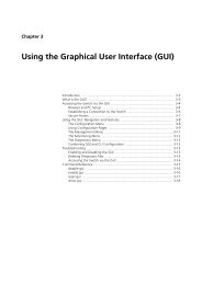
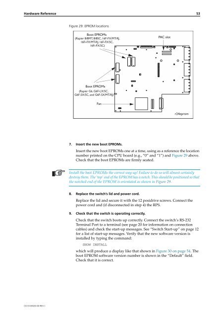
Figure 29: EPROM locations<br />
Boot EPROMs<br />
(<strong>Rapier</strong> 8/8MT, 8/8SC, 16F-FX/MT-RJ,<br />
16Fi-FX/MT-RJ, 16F-FX/SC,<br />
16Fi-FX/SC)<br />
Boot EPROMs<br />
(<strong>Rapier</strong> G6, G6F-LX/SC,<br />
G6F-SX/SC, and G6F-SX/MT-RJ)<br />
Fan<br />
7. Insert the new boot EPROMs.<br />
Insert the new boot EPROMs one at a time, using as a reference the location<br />
number printed on the CPU board (e.g., “0” and “1”) and Figure 29 above.<br />
Check that the boot EPROMs are firmly seated.<br />
Install the boot EPROMs the correct way up! Failure to do so will almost certainly<br />
destroy them. The ‘top’ end of the EPROM has a notch. This should be positioned so that<br />
the notched end of the EPROM is orientated as shown in Figure 29.<br />
8. Replace the switch’s lid and power cord.<br />
Replace the lid and secure it with the 12 posidrive screws. Connect the<br />
power cord and (if disconnected in step 4) the RPS.<br />
9. Check that the switch is operating correctly.<br />
Check that the switch boots up correctly. Connect the switch’s RS-232<br />
Terminal Port to a terminal (see page 20 for information on connection<br />
cables) and check the start-up messages. See “<strong>Switch</strong> Start-up” on page 12<br />
for a list of start-up messages. Verify that the new software version is<br />
installed by typing the command:<br />
SHOW INSTALL<br />
PAC slot<br />
r24eprom<br />
which will produce a display like that shown in Figure 30 on page 54. The<br />
boot EPROM software version number is shown in the “Default” field.<br />
Check that it is correct.