Rapier Series Switch Hardware Reference - Allied Telesis
Rapier Series Switch Hardware Reference - Allied Telesis
Rapier Series Switch Hardware Reference - Allied Telesis
You also want an ePaper? Increase the reach of your titles
YUMPU automatically turns print PDFs into web optimized ePapers that Google loves.
<strong>Hardware</strong> <strong>Reference</strong> 45<br />
C613-03020-00 REV J<br />
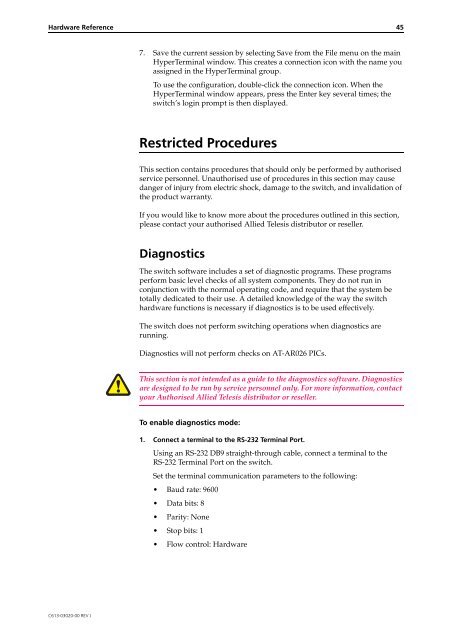
7. Save the current session by selecting Save from the File menu on the main<br />
HyperTerminal window. This creates a connection icon with the name you<br />
assigned in the HyperTerminal group.<br />
To use the configuration, double-click the connection icon. When the<br />
HyperTerminal window appears, press the Enter key several times; the<br />
switch’s login prompt is then displayed.<br />
Restricted Procedures<br />
This section contains procedures that should only be performed by authorised<br />
service personnel. Unauthorised use of procedures in this section may cause<br />
danger of injury from electric shock, damage to the switch, and invalidation of<br />
the product warranty.<br />
If you would like to know more about the procedures outlined in this section,<br />
please contact your authorised <strong>Allied</strong> <strong>Telesis</strong> distributor or reseller.<br />
Diagnostics<br />
The switch software includes a set of diagnostic programs. These programs<br />
perform basic level checks of all system components. They do not run in<br />
conjunction with the normal operating code, and require that the system be<br />
totally dedicated to their use. A detailed knowledge of the way the switch<br />
hardware functions is necessary if diagnostics is to be used effectively.<br />
The switch does not perform switching operations when diagnostics are<br />
running.<br />
Diagnostics will not perform checks on AT-AR026 PICs.<br />
This section is not intended as a guide to the diagnostics software. Diagnostics<br />
are designed to be run by service personnel only. For more information, contact<br />
your Authorised <strong>Allied</strong> <strong>Telesis</strong> distributor or reseller.<br />
To enable diagnostics mode:<br />
1. Connect a terminal to the RS-232 Terminal Port.<br />
Using an RS-232 DB9 straight-through cable, connect a terminal to the<br />
RS-232 Terminal Port on the switch.<br />
Set the terminal communication parameters to the following:<br />
Baud rate: 9600<br />
Data bits: 8<br />
Parity: None<br />
Stop bits: 1<br />
Flow control: <strong>Hardware</strong>


