Rapier Series Switch Hardware Reference - Allied Telesis
Rapier Series Switch Hardware Reference - Allied Telesis
Rapier Series Switch Hardware Reference - Allied Telesis

You also want an ePaper? Increase the reach of your titles
YUMPU automatically turns print PDFs into web optimized ePapers that Google loves.
<strong>Hardware</strong> <strong>Reference</strong> 25<br />
C613-03020-00 REV J<br />
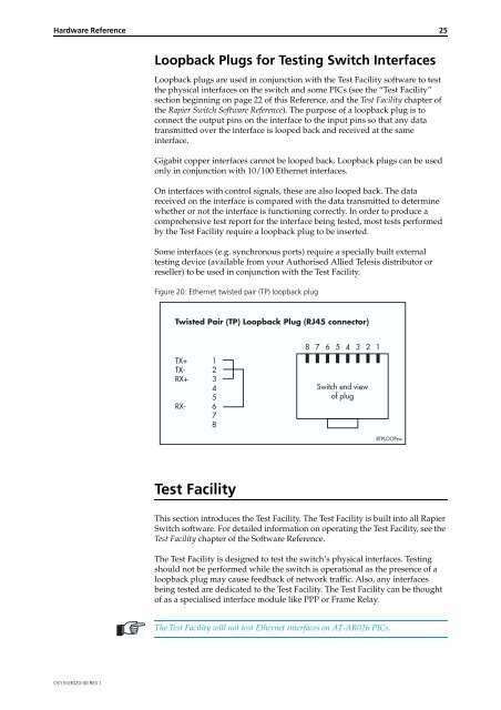
Loopback Plugs for Testing <strong>Switch</strong> Interfaces<br />
Loopback plugs are used in conjunction with the Test Facility software to test<br />
the physical interfaces on the switch and some PICs (see the “Test Facility”<br />
section beginning on page 22 of this <strong>Reference</strong>, and the Test Facility chapter of<br />
the <strong>Rapier</strong> <strong>Switch</strong> Software <strong>Reference</strong>). The purpose of a loopback plug is to<br />
connect the output pins on the interface to the input pins so that any data<br />
transmitted over the interface is looped back and received at the same<br />
interface.<br />
Gigabit copper interfaces cannot be looped back. Loopback plugs can be used<br />
only in conjunction with 10/100 Ethernet interfaces.<br />
On interfaces with control signals, these are also looped back. The data<br />
received on the interface is compared with the data transmitted to determine<br />
whether or not the interface is functioning correctly. In order to produce a<br />
comprehensive test report for the interface being tested, most tests performed<br />
by the Test Facility require a loopback plug to be inserted.<br />
Some interfaces (e.g. synchronous ports) require a specially built external<br />
testing device (available from your Authorised <strong>Allied</strong> <strong>Telesis</strong> distributor or<br />
reseller) to be used in conjunction with the Test Facility.<br />
Figure 20: Ethernet twisted pair (TP) loopback plug<br />
Twisted Pair (TP) Loopback Plug (RJ45 connector)<br />
TX+<br />
TX-<br />
RX+<br />
RX-<br />
1<br />
2<br />
3<br />
4<br />
5<br />
6<br />
7<br />
8<br />
Test Facility<br />
Not<br />
connected<br />
Not<br />
connected<br />
•Not<br />
This section introduces the Test Facility. The Test Facility is built into all <strong>Rapier</strong><br />
<strong>Switch</strong> software. For detailed information on operating the Test Facility, see the<br />
Test Facility chapter of the Software <strong>Reference</strong>.<br />
The Test Facility is designed to test the switch’s physical interfaces. Testing<br />
should not be performed while the switch is operational as the presence of a<br />
loopback plug may cause feedback of network traffic. Also, any interfaces<br />
being tested are dedicated to the Test Facility. The Test Facility can be thought<br />
of as a specialised interface module like PPP or Frame Relay.<br />
The Test Facility will not test Ethernet interfaces on AT-AR026 PICs.<br />
8<br />
7<br />
6<br />
5<br />
4<br />
3<br />
<strong>Switch</strong> end view<br />
of plug<br />
2<br />
1<br />
RTPLOOPsw