Intelligence, Surveillance, and Reconnaissance - Spawar
Intelligence, Surveillance, and Reconnaissance - Spawar
Intelligence, Surveillance, and Reconnaissance - Spawar

Create successful ePaper yourself
Turn your PDF publications into a flip-book with our unique Google optimized e-Paper software.
158<br />
INTELLIGENCE, SURVEILLANCE, AND RECONNAISSANCE<br />
ACOUSTIC SENSOR DESIGN<br />
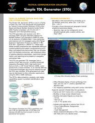
The Hydra acoustic sensor (Figure 4) is composed of a small, air-backed,<br />
piezoelectric hydrophone with a sensitivity of –187 dBV/uPa. A twostage,<br />
low-noise (50 dB/uPa/root Hz over the full b<strong>and</strong>width), lowpower,<br />
3-volt preamplifier provides a gain of 50 dB from 10 to 200 Hz. A<br />
unity gain anti-alias filter follows the preamp. A 16-bit analog-to-digital<br />
converter samples the filter output at 600 samples per second. All digital<br />
telemetry is h<strong>and</strong>led by a low-power field programmable gate array<br />
(FPGA).<br />
NON-ACOUSTIC SENSOR DESIGN<br />
Non-acoustic sensors are distributed along both arrays to facilitate localization<br />
of the acoustic elements by measuring heading, tilt, <strong>and</strong> depth. In<br />
addition to the telemetry interface FPGA, each non-acoustic sensor uses<br />
a microcontroller to decode comm<strong>and</strong>s, control the conversion processes,<br />
<strong>and</strong> format <strong>and</strong> preprocess data. To conserve power, the microcontroller<br />
remains in sleep mode unless a comm<strong>and</strong> is received from the node,<br />
which controls the non-acoustic sensor sample rate (Kelp: once per<br />
minute; Hydra: once per hour). An 18-bit Sigma-Delta ADC, with<br />
integral gain <strong>and</strong> filter, samples the sensor outputs.<br />
Array tilt (Kelp only) is measured by a two-axis accelerometer. This<br />
measurement also serves to correct the output of the three-axis heading<br />
magnetometer for tilt. The pressure sensor is exposed to ambient pressure<br />
via a small ceramic chimney filled with a pliable potting material.<br />
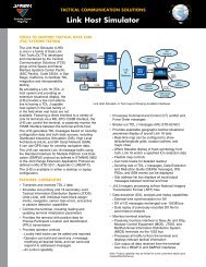
TELEMETRY<br />
Hydra <strong>and</strong> Kelp implement a noise-resistant digital time-division multiplexed<br />
telemetry scheme (Figure 5). The clock is partitioned into six<br />
acoustic data slots, one submultiplexed non-acoustic sensor slot, <strong>and</strong> a<br />
reset <strong>and</strong> comm<strong>and</strong> interval. Non-acoustic sensors, i.e., compass, tilt,<br />
temperature, <strong>and</strong> pressure, are multiplexed into the engineering sensor<br />
slot. The reset <strong>and</strong> comm<strong>and</strong> interval synchronizes the sensors <strong>and</strong> allows<br />
the node to send comm<strong>and</strong>s to them. A low-power FPGA in each sensor<br />
detects the reset interval, <strong>and</strong> begins an ADC; acoustic sensor outputs are<br />
simultaneously sampled. Then each sensor counts clock edges <strong>and</strong> places<br />
its data on the data conductor when its turn arrives.<br />
Each data sample is an asynchronous bit stream with 2 start bits, 2<br />
address bits to identify the data’s origin, 16 data bits, <strong>and</strong> 1 stop bit. The<br />
node FPGA implements a universal asynchronous receive <strong>and</strong> transmit<br />
(UART)-style detector to decode the data stream. The data are then<br />
briefly buffered in parallel first in, first out (FIFOs) inside the FPGA<br />
<strong>and</strong> formatted for output to the DSP <strong>and</strong> data-recording subsystem.<br />
NODE<br />
The interchangeable Hydra <strong>and</strong> Kelp nodes (Figure 6) perform the following<br />
functions: (1) generate timing signals for multiplex synchronization,<br />
(2) send comm<strong>and</strong>s to the acoustic <strong>and</strong> non-acoustic sensors, (3)<br />
format the inbound digital data stream for the recording subsystem <strong>and</strong><br />
for processing by the DSPs, <strong>and</strong> (4) report results via an underwater<br />
acoustic modem.<br />
FIGURE 4. The acoustic (right) <strong>and</strong> nonacoustic<br />
(left) sensor circuit boards shown<br />
above are enclosed in a thin plastic form<br />
<strong>and</strong> filled with low viscosity polyurethane<br />
for waterproofing. Weights are added at<br />
the cable entrance <strong>and</strong> exit points to increase<br />
the package specific gravity to 1.8.<br />
COMMANDS<br />
CLOCK<br />
1 2 3 4 5 6 E<br />
SENSORS<br />
RESET<br />
DATA<br />
START<br />
STOP<br />
FIGURE 5. Hydra <strong>and</strong> Kelp implement a<br />
digital time-division multiplexing telemetry<br />
scheme. The FPGA in the node generates<br />
an array clock that delineates the data slot<br />
times assigned to a particular sensor.