Synthesis of a parallel-coupled ring-resonator filter - Dipartimento di ...
Synthesis of a parallel-coupled ring-resonator filter - Dipartimento di ...
Synthesis of a parallel-coupled ring-resonator filter - Dipartimento di ...

Create successful ePaper yourself
Turn your PDF publications into a flip-book with our unique Google optimized e-Paper software.
June 15, 2001 / Vol. 26, No. 12 / OPTICS LETTERS 917<br />
<strong>Synthesis</strong> <strong>of</strong> a <strong>parallel</strong>-<strong>coupled</strong> <strong>ring</strong>-<strong>resonator</strong> <strong>filter</strong><br />
Andrea Melloni<br />
<strong>Dipartimento</strong> <strong>di</strong> Elettronica e Informazione, Politecnico <strong>di</strong> Milano, Via Ponzio 34/5, 20133 Milan, Italy<br />
Received January 3, 2001<br />
An effective and exact synthesis technique for the design <strong>of</strong> <strong>parallel</strong>-<strong>coupled</strong> <strong>ring</strong>-<strong>resonator</strong> <strong>filter</strong>s with a<br />
maximally f lat stop-band characteristic <strong>of</strong> any order is presented. Simple closed-form formulas determine<br />
the Q factor <strong>of</strong> each <strong>resonator</strong> and the coupling coefficients. The performances <strong>of</strong> these <strong>filter</strong>s are <strong>di</strong>scussed<br />
for their applications as interleavers and channel-dropping <strong>filter</strong>s in wavelength-<strong>di</strong>vision multiplexing systems.<br />
© 2001 Optical Society <strong>of</strong> America<br />
OCIS codes: 130.1750, 230.3120, 230.5750, 060.4230.<br />
Selective bandpass <strong>filter</strong>s are a key component in<br />
modern dense wavelength-<strong>di</strong>vision multiplexing systems<br />
that are characterized by small channel spacing<br />
and high bit rates. The required characteristics are<br />
high selectivity, that is, the ability to separate two<br />
adjacent channels; high rejection out <strong>of</strong> band, which<br />
guarantees low cross talk between channels; f lat<br />
in-band response, a requirement that is <strong>of</strong>ten related<br />
to maximum group-delay <strong>di</strong>stortion; and, if possible,<br />
low insertion losses. 1<br />
In this Letter a simple and exact technique for the<br />
synthesis <strong>of</strong> bandpass <strong>filter</strong>s is presented, for the first<br />
time to the author’s knowledge. Such a <strong>filter</strong> is realized<br />
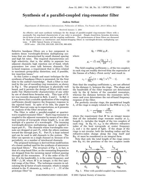
by the use <strong>of</strong> casca<strong>di</strong>ng <strong>ring</strong> <strong>resonator</strong>s, as shown<br />
in Fig. 1. The proposed technique is physically well<br />
based, and it permits the design <strong>of</strong> <strong>filter</strong>s with maximally<br />
f lat (Butterworth) characteristics <strong>of</strong> any order<br />
by use <strong>of</strong> closed-form formulas only. This type <strong>of</strong> <strong>filter</strong><br />
was recently <strong>di</strong>scussed in Refs. 2 and 3. In Ref. 2<br />
it was shown that a suitable apo<strong>di</strong>zation <strong>of</strong> the coupling<br />
coefficients should improve the frequency response in<br />
the rejected band. In spite <strong>of</strong> its title, the paper by<br />
Griffel 3 does not come up to expectations, as it presents<br />
an analysis <strong>of</strong> the <strong>filter</strong> structure only.<br />
The <strong>filter</strong> is called a <strong>parallel</strong>-<strong>coupled</strong> or quarterwave-<strong>coupled</strong><br />
<strong>resonator</strong> <strong>filter</strong>. 4 Each <strong>ring</strong> <strong>resonator</strong> is<br />
<strong>coupled</strong> to the adjacent <strong>resonator</strong> by means <strong>of</strong> two identical<br />
sections <strong>of</strong> waveguide whose length Lc is an odd<br />
multiple <strong>of</strong> a quarter <strong>of</strong> a wavelength. The incoming<br />
wavelength-<strong>di</strong>vision multiplexing signal is applied to<br />
input port P1. The channels whose wavelengths resonate<br />
are dropped at port P2, while the others continue<br />
toward the through port, P3. Port P4 is kept isolated<br />
and can be used to add channels to the system. The<br />
<strong>filter</strong> can operate on a single channel or, because <strong>of</strong> its<br />
perio<strong>di</strong>city, on a number <strong>of</strong> interleaved channels.<br />
The proposed technique is derived from mo<strong>di</strong>fication<br />
<strong>of</strong> a classic method used for the synthesis <strong>of</strong> microwave<br />
stop-band <strong>filter</strong>s. 4 The structure <strong>of</strong> Fig. 1, in fact, is<br />
that <strong>of</strong> a stop-band <strong>filter</strong>, as the resonating frequencies<br />
are dropped from the incoming signal without passing<br />
through all the <strong>resonator</strong>s. N is the order <strong>of</strong> the <strong>filter</strong>,<br />
B is the bandwidth, f0 is the center frequency, and<br />
FSR f0M, where M is an integer, is the free spectral<br />
range <strong>of</strong> the <strong>filter</strong>. The technique consists in calculating<br />
the Q factor <strong>of</strong> each <strong>resonator</strong>, which is simply<br />
related to the N elements gq (with q 1 ... N) <strong>of</strong> the<br />
prototype <strong>filter</strong> 4 by<br />
where<br />
Qq FSRgqB , (1)<br />
gq p µ<br />
2q 2 1<br />
2 sin<br />
2N p<br />
∂<br />
. (2)<br />
The field coupling coefficients cq <strong>of</strong> the two couplers<br />
in each <strong>ring</strong> are rea<strong>di</strong>ly derived from the expression <strong>of</strong><br />
the finesse <strong>of</strong> a Fabry–Perot cavity 5 and result in<br />
cq p2<br />
2Qq 2 1 1 4Qq 2 p 2 1/2<br />
2 1 . (3)<br />
Note that the coupling coefficients cq are not affected<br />
by the <strong>di</strong>stance Lc between the <strong>ring</strong>s. The shape and<br />
the bandwidth <strong>of</strong> the <strong>filter</strong> response are determined<br />
only by the Q factors <strong>of</strong> the cascaded <strong>resonator</strong>s,<br />
whereas the <strong>di</strong>stance between the <strong>resonator</strong>s inf luences<br />
and even determines the out-<strong>of</strong>-band frequency<br />
response <strong>of</strong> the <strong>filter</strong>.<br />
For perfectly circular <strong>ring</strong>s, the geometrical length<br />
Lr <strong>of</strong> the <strong>ring</strong>s is simply related to the FSR or to f0 by<br />
c cM<br />
Lr , (4)<br />
neff FSR neff f0<br />
where the requirement that M be an integer means<br />
that all the unloaded <strong>ring</strong>s resonate exactly at f0.<br />
Length Lr includes the length <strong>of</strong> the two couplers <strong>of</strong><br />
each <strong>ring</strong>. In Eq. (4), neff is the effective refractive<br />
index <strong>of</strong> the bent waveguide at center frequency<br />
f0 and c is the speed <strong>of</strong> light. If the shape <strong>of</strong> the<br />
<strong>ring</strong>s is not circular, both the ben<strong>di</strong>ng ra<strong>di</strong>us and the<br />
refractive-index change along the <strong>ring</strong> itself and<br />
Eq. (4) must be considered in an integral form.<br />
Note that only the total length <strong>of</strong> the <strong>ring</strong>s enters<br />
into Eq. (4); the positions <strong>of</strong> the two couplers inside<br />
Fig. 1. Filter with <strong>parallel</strong>-<strong>coupled</strong> <strong>ring</strong> <strong>resonator</strong>s.<br />
0146-9592/01/120917-03$15.00/0 © 2001 Optical Society <strong>of</strong> America
918 OPTICS LETTERS / Vol. 26, No. 12 / June 15, 2001<br />
each <strong>ring</strong> are arbitrary. This means that the <strong>ring</strong>s<br />
should not necessarily be placed in line and, if necessary,<br />
the <strong>filter</strong> can be folded as for the cross-grid<br />
node consisting <strong>of</strong> a pair <strong>of</strong> micro<strong>ring</strong> <strong>resonator</strong>s as <strong>di</strong>scussed<br />
in Ref. 6.<br />
Length Lc <strong>of</strong> the coupling waveguides should be as<br />
nearly equal as possible to an odd multiple <strong>of</strong> a quarter-wavelength<br />
over the whole operating frequency<br />
band <strong>of</strong> the <strong>filter</strong>. In other words, Lc must be the<br />
smallest possible. Even more generally, 2Lc should be<br />
a small odd multiple <strong>of</strong> a half-wavelength. However,<br />
because <strong>of</strong> the large <strong>di</strong>mensions <strong>of</strong> the <strong>ring</strong>s compared<br />
with the wavelength, to fulfill this requirement the<br />
<strong>ring</strong>s cannot be placed too close to one another, to<br />
avoid superposition, and this restriction affects the<br />
operating frequency band <strong>of</strong> the <strong>filter</strong>. For circular<br />
<strong>ring</strong>s, the minimum <strong>di</strong>stance is twice the <strong>ring</strong> ra<strong>di</strong>us.<br />
When 2Lc is an odd multiple <strong>of</strong> half a wavelength,<br />
the contributions <strong>of</strong> all the <strong>ring</strong>s add in phase at the<br />
resonating frequencies, and the signal is dropped at the<br />
output port. However, when out <strong>of</strong> band, the contributions<br />
do not add in phase, and at some frequencies<br />
they even cancel completely and create transmission<br />
nulls in the frequency response. This is a nice feature<br />
<strong>of</strong> this type <strong>of</strong> <strong>filter</strong>, as the out-<strong>of</strong>-band rejection<br />
increases.<br />
A number <strong>of</strong> examples demonstrate the capability <strong>of</strong><br />
the proposed technique to design <strong>parallel</strong>-<strong>coupled</strong> <strong>filter</strong>s<br />
and also show both the advantages and the limitations<br />
<strong>of</strong> this type <strong>of</strong> <strong>filter</strong>. The inf luence <strong>of</strong> <strong>di</strong>stance<br />
Lc on the frequency response <strong>of</strong> the <strong>filter</strong>s is also investigated,<br />
up to Lc Lr2. Larger values <strong>of</strong> Lc are<br />
<strong>of</strong> small interest and are not <strong>di</strong>scussed here. We carry<br />
out the spectral analysis by casca<strong>di</strong>ng the transmission<br />
matrices <strong>of</strong> the various buil<strong>di</strong>ng blocks <strong>of</strong> the structure.<br />
As a first example, a bandpass <strong>filter</strong> with FSRB <br />
10 is considered. Distance Lc has been chosen very<br />
small, Lc Lr100l/4, where the subscript means the<br />
odd multiple <strong>of</strong> a quarter-wavelength closer to Lr100.<br />
The <strong>ring</strong>s have a strongly elliptical shape, with a minimum<br />
ben<strong>di</strong>ng ra<strong>di</strong>us that can be supported only by<br />
highly confined waveguides such as those described in<br />
Refs. 2 and 6. As an example, a FSR <strong>of</strong> 100 GHz requires<br />
a minimum ben<strong>di</strong>ng ra<strong>di</strong>us equal to 15neff mm.<br />
Higher FSRs require even smaller ben<strong>di</strong>ng ra<strong>di</strong>i, which<br />
depend on FSR 21 .<br />
Figure 2 shows the frequency responses <strong>of</strong> the <strong>filter</strong>s<br />
for orders from 2 to 5, over two FSRs. The bandpass<br />
characteristic is f lat (maximally f lat), and the bandwidth<br />
at 23 dB is independent <strong>of</strong> order N. Note the<br />
transmission zeros that appear between the dropped<br />
bands: Such a feature permits a very low level <strong>of</strong><br />
cross talk to be attained, even with a low order <strong>of</strong> the<br />
<strong>filter</strong>. Increasing the order makes the frequency response<br />
more selective; the number <strong>of</strong> transmission zeros<br />
increases, too.<br />
If the <strong>di</strong>stance between <strong>ring</strong>s is much smaller then<br />
the <strong>ring</strong> half-length, it is possible to take advantage<br />
<strong>of</strong> the perio<strong>di</strong>city <strong>of</strong> the frequency response. The<br />
smaller Lc, the higher the number <strong>of</strong> usable FSRs.<br />
Figure 3 shows the frequency response <strong>of</strong> a fourthorder<br />
<strong>filter</strong> with FSR 100 GHz, B 20 GHz, and<br />
Lc Lr100l/4. As above, long and narrow <strong>ring</strong>s<br />
with a minimum ben<strong>di</strong>ng ra<strong>di</strong>us <strong>of</strong> 15neff mm haveto<br />
be packed very close to one another.<br />
Note that both the shape <strong>of</strong> the dropped bands<br />
and the out-<strong>of</strong>-band rejection remain acceptable for<br />
15 FSRs. The deterioration in frequency response<br />
is due to the variation <strong>of</strong> the phase shift induced in<br />
the frequency by Lc, but the nulls between subsequent<br />
dropped bands are maintained. The <strong>filter</strong> considered<br />
in this example can be used as an interleaver to<br />
separate odd from even channels in a 32-channel,<br />
50-GHz spaced, wavelength-<strong>di</strong>vision multiplexing<br />
system. As a rule <strong>of</strong> thumb, the number <strong>of</strong> channels<br />
that can be managed by an interleaver produced by<br />
<strong>parallel</strong>-<strong>coupled</strong> <strong>ring</strong> <strong>resonator</strong>s is Lr3Lc.<br />
To investigate how the <strong>di</strong>stance between the <strong>ring</strong>s<br />
inf luences the frequency response, let us consider a<br />
third-order <strong>filter</strong> with FSRB 10 and three values<br />
<strong>of</strong> Lc. Figure 4 shows each frequency response <strong>of</strong> the<br />
three <strong>filter</strong>s with <strong>di</strong>stances Lc rounded to l4. When<br />
<strong>di</strong>stance Lc is increased, the transmission nulls move<br />
toward the dropped band, and the rejection decreases.<br />
With Lc Lrpl/4, which corresponds to two circular<br />
<strong>ring</strong>s placed as close to each other as possible,<br />
although the bandpass remains un<strong>di</strong>storted the rejection<br />
out <strong>of</strong> band is unacceptable. Moreover, the <strong>filter</strong><br />
Fig. 2. Frequency responses for N 2...5and FSRB <br />
10. Lc Lr100l/4.<br />
Fig. 3. Frequency response for a fourth-order <strong>filter</strong> with<br />
FSR 100 GHz, B 20 GHz, and Lc Lr100l/4.
Fig. 4. Frequency response <strong>of</strong> a third-order <strong>filter</strong> with<br />
FSRB 10 and three values <strong>of</strong> Lc (rounded to l4).<br />
Fig. 5. Frequency response <strong>of</strong> a fourth-order <strong>filter</strong> with<br />
FSRB 30 and two values <strong>of</strong> Lc.<br />
ceases to be perio<strong>di</strong>c and cannot be used for interleaving.<br />
A possible application in the case <strong>of</strong> large Lc (up<br />
to Lc Lrp) consists <strong>of</strong> single-channel selection. As<br />
an example, for N 3, FSR 1200 GHz, B 10 GHz,<br />
June 15, 2001 / Vol. 26, No. 12 / OPTICS LETTERS 919<br />
and Lc Lrpl/4, the rejected band is 0.9 FSR and<br />
the <strong>ring</strong> ra<strong>di</strong>us is 40neff mm.<br />
As a last example, a <strong>filter</strong> with Lc Lr2 is observed.<br />
In this case, the two sections Lc considered<br />
together have the same length as the <strong>ring</strong>s themselves.<br />
If <strong>di</strong>stance Lc is equal to the odd multiple <strong>of</strong> a quarterwavelength<br />
closer to Lr2, the <strong>filter</strong> has poor rejection,<br />
as shown in Fig. 5 [labeled Lr2l/4]. In such a figure,<br />
a fourth-order <strong>filter</strong> with FSRB 30 is considered.<br />
If Lc Lr2, however, the frequency response is substantially<br />
mo<strong>di</strong>fied: The dropped bands widen considerably,<br />
they are not maximally f lat, and the rejection<br />
out-<strong>of</strong>-band values are excellent as the transmission<br />
nulls move in. In this case the minimum ben<strong>di</strong>ng ra<strong>di</strong>us<br />
depends on the FSR only.<br />
The <strong>filter</strong> characteristic is perio<strong>di</strong>c, as in the first example.<br />
Possible applications <strong>of</strong> this design are either<br />
in interleaving or in single-channel selection. Without<br />
ente<strong>ring</strong> into details, however, it can be said that a<br />
perfect compensation between a transmission null with<br />
<strong>ring</strong> resonance occurs at the center frequencies. This<br />
is a critical situation, as any <strong>di</strong>screpancy with respect<br />
to the ideal <strong>di</strong>mensions produces a deep notch in the<br />
dropped bands.<br />
In conclusion, the proposed synthesis technique<br />
is precise and f lexible and uses only closed-form<br />
formulas. Both channel-selective <strong>filter</strong>s and interleavers<br />
can be designed accor<strong>di</strong>ng to specifications <strong>of</strong><br />
bandwidth, FSR, out-<strong>of</strong>-band rejection, and selectivity.<br />
The <strong>di</strong>stance between the <strong>ring</strong>s plays an important<br />
role in the overall frequency response.<br />
The author’s e-mail address is melloni@elet.polimi.it.<br />
References<br />
1. C. K. Madsen and J. H. Zhao, Optical Filter Design and<br />
Analysis (Wiley, New York, 1999).<br />
2. B. E. Little, S. T. Chu, J. V. Hryniewicz, and P. Absil,<br />
Opt. Lett. 25, 344 (2000).<br />
3. G. Griffel, IEEE Photon. Technol. Lett. 12, 810 (2000).<br />
4. G. L. Matthaei, L. Young, and E. M. T. Jones, in<br />
Microwave Filters, Impedance Matching Networks and<br />
Coupling Structures (McGraw-Hill, New York, 1964).<br />
5. H. A. Haus, Waves and Fields in Optoelectronics (Prentice-Hall,<br />
Englewood Cliffs, N. J., 1984).<br />
6. S. T. Chu, B. E. Little, W. Pan, T. Kaneko, and Y.<br />
Kokubun, IEEE Photon. Technol. Lett. 11, 1426 (1999).