Eclipse stemless shoulder
Eclipse stemless shoulder
Eclipse stemless shoulder

You also want an ePaper? Increase the reach of your titles
YUMPU automatically turns print PDFs into web optimized ePapers that Google loves.
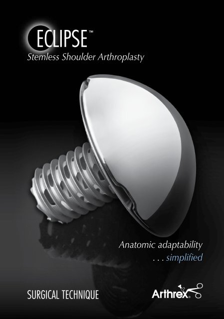
ECLIPSE TM<br />
Stemless Shoulder Arthroplasty<br />
SURGICAL<br />
SURGICAL<br />
TECHNIQUE<br />
TECHNIQUE<br />
Anatomic adaptability<br />
. . . simplified
INTRodUCTIoN<br />
dESIGN RATIoNALE<br />
With the evolving treatment of glenohumeral joint disease, we understand<br />
that current resurfacing, total <strong>shoulder</strong> arthroplasty and hemiarthroplasty<br />
surgical options are not without obstacles and hazards. Current resurfacing<br />
devices provide a less than ideal solution based on considerable difficulties<br />
with primary and secondary glenoid replacement. In addition, revision of<br />
a conventional stemmed implant often demands osteotomy of the humeral<br />
shaft with an elevated rate of morbidity. Given these issues, a modern<br />
solution for glenohumeral arthritis, especially in younger patients, is essential.<br />
The <strong>Eclipse</strong> system strikes a balance between conventional resurfacing and<br />
standard stemmed devices with several key advantages:<br />
• Humeral head can be positioned independently of the humeral<br />
shaft axis, especially important in post traumatic arthritis situations<br />
• Excellent anatomic reconstruction of the humeral head as the<br />
prosthesis can be adjusted to the cortical rim of the humeral<br />
resection at the anatomical neck<br />
• Eight anatomic head sizes available in 2 mm increments<br />
• Fenestrated cage screw for enhanced fixation<br />
• Multiple cage screw lengths account for anatomical variations<br />
• Unrestricted approach to the glenoid<br />
• Simplified revision arthroplasty and avoidance of complications<br />
associated with humeral shaft osteotomy<br />
• Potential for less invasive exposure<br />
Prof. Dr. med. habil. Peter Habermeyer<br />
ATOS Clinic – Heidelberg, Germany<br />
This device is not yet cleared by the FDA for sale in the U.S.<br />
Currently available outside the U.S.
1<br />
GLENoId oPTIoNS<br />
Keeled Glenoid:<br />
• Dual fenestrations for enhanced anchoring<br />
• Reverse barbs for expansion effect within<br />
the glenoid vault<br />
Pegged Glenoid:<br />
• Unique 2-pegged design features a curved<br />
keel with reverse barbs and large fenestration<br />
for excellent fixation strength
SURGICAL APPRoACH<br />
As described by Anthony Romeo, M.D., Rush University Medical Center, Chicago, IL<br />
1. PATIENT PoSITIoNING<br />
Following general anesthesia, the patient is placed in the beach chair (semi-sitting) position. Typically,<br />
the angle is 30°- 45° of elevation with respect to the operating room floor. The head and neck are secured<br />
using a ring headrest which is helpful for maintaining the head and neck position throughout the procedure.<br />
The endotracheal tube and intravenous lines are positioned on the contralateral side of the affected <strong>shoulder</strong>.<br />
The upper body is brought to the edge of the operating room table to allow full extension of the arm,<br />
which is essential for the exposure of the proximal humerus. A folded towel is placed behind the medial<br />
border of the scapula to stabilize the position of the glenoid throughout the procedure. A sterile preparation<br />
and draping is performed on the <strong>shoulder</strong> and arm to allow full exposure and free movement of the entire<br />
limb.<br />
2. INCISIoN ANd EXPoSURE<br />
The deltopectoral incision begins at the inferior border of the midsection of the clavicle, proceeds at<br />
an angle past the medial aspect of the coracoid prominence, and ends at the superior aspect of the axillary<br />
fold. The skin incision often lies directly over the cephalic vein, and therefore the interval between the<br />
deltoid and pectoralis major muscles.<br />
The cephalic vein clearly defines the junction between the deltoid and pectoralis major muscles. If the<br />
vein is not readily identified, the prominence of the coracoid also marks the deltopectoral interval, or the<br />
surgeon can identify the fibrous portion of the superior aspect of the pectoralis tendon at the distal part<br />
of the incision. The vein can be mobilized medially or laterally.<br />
The conjoined tendon complex, consisting of the short head of the biceps and the coracobrachialis<br />
muscle, is identified. The muscular portion of the biceps (red) is the most lateral part of the conjoined<br />
tendon, with the tendinous portion (white) just medial to the visible muscle. The approach through<br />
the clavipectoral fascia is just lateral to the “red stripe” representing the muscular portion of the short<br />
head of the biceps. The deltoid muscle is carefully mobilized laterally and protected. The coracoacromial<br />
ligament is maintained (not released). A thin retractor (e.g. Homann or Darrach) is placed under the<br />
coracoacromial ligament to provide exposure to the superior aspect of the subscapularis and humerus.<br />
Retraction of the deltoid and pectoralis major is maintained with a self-retaining retractor. The superior<br />
1-2 cm of the pectoralis tendon can be released to provide additional exposure to the inferior aspect of<br />
the subscapularis and the anterior circumflex vessels. The arm is then externally rotated to further expose<br />
the boundaries of the subscapularis muscle and tendon insertion. The superior aspect of the subscapularis<br />
tendon is at the level of the coracoid tip and can be clearly identified by excising part of the subcoracoid<br />
bursa and rotator interval capsule. The inferior border of the subscapularis tendon is at the level of the<br />
anterior circumflex vessels. This group of vessels includes the anterior circumflex artery bordered by two<br />
anterior circumflex veins and is commonly referred to as the “Three Sisters”. The lateral border of the<br />
subscapularis tendon is identified just medial to the bicipital groove. Two tag stitches using #2 FiberWire ®<br />
are placed into the medial aspect of the subscapularis tendon in preparation for the subscapularis release.<br />
3. SUbSCAPULARIS RELEASE<br />
For uncomplicated <strong>shoulder</strong> arthroplasty a transtendon approach is preferred, leaving 5 mm of tendon<br />
attached to the lesser tuberosity for later repair of the tendon to both the bone and the remaining tendon.<br />
The subscapularis tendon is entirely released beginning at the rotator interval and proceeding inferiorly<br />
below the level of the anterior circumflex vessels, continuing along the humeral neck. The humerus is<br />
externally rotated to facilitate the release of the capsule from the humerus to the 6 o’clock position on the<br />
humerus.<br />
2
SURGICAL APPRoACH<br />
3<br />
4. GLENoHUmERAL CAPSULE RELEASE<br />
Once the subscapularis tendon is released from the humerus, the surgeon has an opportunity to release<br />
the anterior and inferior capsule with excellent direct visualization. This capsular release is a routine part<br />
of <strong>shoulder</strong> arthroplasty for patients with a loss of external rotation, most commonly seen in osteoarthritis<br />
patients. A ring retractor (e.g. Fukuda) is placed across the glenohumeral joint and hooked on the posterior<br />
glenoid. The retractor is used to sublux the humerus, posterior and lateral, placing tension in the inferior<br />
capsule. The junction between the muscular portion of the subscapularis (red) and the capsule (white) is<br />
clearly identified. The axillary nerve is generally just inferior to the muscular portion of the subscapularis<br />
or less than 1 cm from the capsule. The nerve should be identified and protected. With tension in the<br />
capsule, it is released from lateral to medial, ending at the 6 o’clock position on the glenoid. The anterior<br />
capsule is bluntly separated from the subscapularis and sharply incised (capsulotomy). Finally, the fibrous<br />
attachments from the lateral aspect of the coracoid to the subscapularis are released completing mobilization<br />
of the subscapularis when combined with the anterior/inferior capsulotomy. The release should remain<br />
lateral to the coracoid process to avoid injury to the nerve of the subscapularis and the brachial plexus.<br />
The lack of bone preparation at this stage of the procedure provides excellent visualization of all the<br />
involved structures, particularly the capsule and its relationship to the axillary nerve. The subscapularis tendon<br />
is displaced medially under the coracoid process and held away from the surgical site with the self-retaining<br />
retractor, in anticipation of preparation of the humerus. Glenohumeral capsular release combined with<br />
anatomic reconstruction of the humeral articular surface are essential to provide the maximum potential for<br />
improved range of motion and function.<br />
5. HUmERAL HEAd RESECTIoN<br />
The humerus is dislocated from the glenoid using a flat retractor (e.g. Darrach) as a “shoehorn” to<br />
gently guide the humerus out of the glenoid. The arm is externally rotated until a direct view of the entire<br />
humeral articular surface is achieved. This can be facilitated by using a flat retractor medially, as well as<br />
a retractor placed just behind the superior rotator cuff. The arm is held in greater than 90° of external<br />
rotation, 20°-30° of extension, and adduction against the operating room table. If complete exposure<br />
of the humeral head articular surface cannot be accomplished, further capsulotomy may be necessary.<br />
Following exposure of the humeral head including removal of the osteophytes, either a free hand resection<br />
technique or the humeral resection guides (see Step 1) can be used.<br />
6. GLENoId EXPoSURE<br />
Glenoid exposure begins with a complete anterior/inferior capsulotomy which is described in Section 4.<br />
This not only improves the motion postoperatively, but helps with visualization and exposure of the glenoid.<br />
Following the identification and release of the capsule from the anterior/inferior aspect down to the<br />
6 o’clock position, it may be necessary to continue the release further posteriorly, along to the glenoid<br />
margin, to achieve a straight approach to the articular surface of the glenoid. Once the axillary nerve is<br />
identified, the release of the capsule may continue unimpeded until complete visualization of the glenoid<br />
is possible.<br />
If the glenoid remains poorly visualized after the release of the anterior, inferior, and posterior capsule,<br />
additional steps may assist in achieving a direct approach to the glenoid. Full release of the deltopectoral<br />
interval should be confirmed. Additional release of the pectoralis major tendon can be included with repair<br />
of the tendon at the end of the procedure. The superior 1-2 cm of the pectoralis tendon can be released to<br />
increase visualization. On the deltoid side, the anterior attachment of the deltoid on the deltoid tubercle of<br />
the humerus can also be partially released.<br />
Once a direct view of the glenoid is possible, a glenoid neck retractor is placed along the anterior glenoid<br />
neck, as medial as possible. This will help the surgeon with respect to the orientation of the glenoid, especially<br />
in cases where significant posterior erosion has occurred.<br />
In any case, the important principle is to have a direct visualization of the face of the glenoid. Any deviation<br />
in the position of the component can lead to early failure of the arthroplasty.
HUmERAL PREPARATIoN ANd ImPLANTATIoN<br />
Remove osteophytes<br />
with a Rongeur or small<br />
osteotome to identify the<br />
anatomic neck. Either the<br />
left or right, small or large<br />
Resection Guide is placed<br />
on the humeral head.<br />
To determine retroversion,<br />
Version Rods are placed in<br />
the guide at the 20° and<br />
40° positions and aligned<br />
with the forearm with<br />
the elbow flexed 90°.<br />
Typically, the forearm<br />
should be visualized<br />
between the position of<br />
the two Version Rods so<br />
that a retroversion of 30°<br />
is achieved based on the<br />
orientation of the forearm.<br />
1 2<br />
3 4<br />
Two 1.6 mm K-wires are drilled through the holes<br />
of the humeral head Resection Guide until they<br />
exit the opposite cortex at the boundary of the<br />
articular cartilage.<br />
The appropriate guide<br />
size and position will<br />
result in subsequent<br />
pin placement across<br />
the anatomic neck.<br />
Once the appropriate<br />
guide position has<br />
been established, the<br />
2.8 mm Steinman<br />
Pin is advanced down<br />
the center cannulation<br />
of the humeral head<br />
Resection Guide to<br />
secure it to bone.<br />
The Steinman Pin is removed from the center of the<br />
Resection Guide, then the guide is disengaged from<br />
the K-wires. The humeral head is resected with a saw,<br />
using the K-wires as a guide. The resected humeral<br />
head or cut surface of the humerus is compared to<br />
the trial of corresponding size. The proportions<br />
should be noted for subsequent glenoid selection.<br />
4
HUmERAL PREPARATIoN ANd ImPLANTATIoN<br />
5<br />
The K-wires are removed using the Pin Extractor.<br />
Note: If the bone quality is poor (very soft cancellous<br />
bone/osteoporosis), the procedure should be switched<br />
to a stemmed prosthesis.<br />
7<br />
Prepare the hole for the Cage Screw using the<br />
Hand Coring Reamer. In hard bone, it may be<br />
necessary to use the Power Coring Reamer. If a<br />
glenoid replacement is planned, the resected plane<br />
should be protected by using one of the Resection<br />
Protectors from the instrument set (see inset).<br />
5<br />
6<br />
Determine the size of the Trunion by trialing the<br />
various Drill Templates. The Drill Template should<br />
match the resected plane of the cortical rim as<br />
closely as possible.<br />
8<br />
Place the Centering Device into the Drill Template<br />
and push it into the reamed channel in the humeral<br />
cut.
9<br />
Sizing mark<br />
To determine the length of the Cage Screw, drill the<br />
graduated Cage Screw Sizer through the Centering<br />
Device until it reaches the lateral cortex. The size<br />
refers to the distal laser marking on the pin and it is<br />
referenced off the top of the Centering Device. If the<br />
measurements are in between two marks, choose the<br />
shorter screw. Remove the Cage Screw Sizer after the<br />
measurement has been taken.<br />
10 11<br />
A Trunion of the previously determined size is opened<br />
in a sterile fashion. Remove the Drill Template and<br />
place the selected Trunion over the Centering Device.<br />
Optional<br />
Optional: The Trial Trunion and Trial Head can be<br />
used to verify the correct size of the prothesis. The<br />
correct size matches the diameter of the cut surface<br />
of the humerus. The head height is predetermined<br />
due to the fixed relationship of the head diameter<br />
and height based on normal humeral anatomy.<br />
Note: The Drill Template and the Centering Device<br />
must be removed prior to this optional step.<br />
Fix the Trunion to the humeral cut with the Trunion<br />
Impactor and mallet. Remove the Centering Device.<br />
Note: The Trunion should have circumferential contact<br />
with the cortical rim.<br />
6
HUmERAL PREPARATIoN ANd ImPLANTATIoN<br />
12 13<br />
Select the appropriate Cage Screw according to the<br />
previous measurement (Step 9). Advance the Cage<br />
Screw through the center of the Trunion while<br />
holding the Trunion tightly against the resected<br />
surface with the Trunion Impactor.<br />
14 15<br />
When the screw has been fully seated on the neck<br />
of the Trunion, remove the Screwdriver and Trunion<br />
Impactor.<br />
7<br />
Fix the Trunion by tightening the Cage Screw with<br />
the Screwdriver until the screw head is flush with<br />
the neck of the Trunion.<br />
Note: Do not over tighten the screw.<br />
Select the appropriate Humeral Head according to<br />
the previous measurement and size of the Trunion.<br />
The Humeral Head is impacted onto the <strong>Eclipse</strong><br />
Trunion using the Head Impactor.
WoUNd CLoSURE<br />
As described by Anthony Romeo, M.D., Rush University Medical Center, Chicago, IL<br />
Prior to closure, the goals of improved mobility while maintaining stability of the glenohumeral joint should<br />
be assessed with the final implants in place. This can be accomplished intraoperatively using the “40-50-60”<br />
method: A stable 40° of external rotation with the arm in neutral position, 50% posterior translation with<br />
good “bounce-back” of the Humeral Head into the center of the glenoid, and 60° of internal rotation with<br />
the arm in abduction.<br />
Wound closure begins with thorough irrigation, removing any remaining soft tissue or bony debris.<br />
Hemostasis is obtained with electrocautery. The initial focus of wound closure is the repair of the<br />
subscapularis tendon. To ensure that the subscapularis tendon is repaired to its anatomic position, the first<br />
step of the repair is reattaching the superior lateral edge of the subscapularis to the anterior lateral edge of<br />
the supraspinatus directly over the bicipital groove. This is performed with #2 FiberWire sutures. By securing<br />
the superior lateral edge of the subscapularis at the beginning of the repair, the tendon is held in an anatomic<br />
position.<br />
Four braided #5 FiberWire sutures which were placed at the rim of the osteotomy site are individually passed<br />
through the subscapularis tendon separated by approximately 1 cm. The sutures can be passed with a Mason-<br />
Allen configuration to improve security of the suture in the tendon. The sutures are tied beginning superiorly<br />
and proceeding inferiorly. Additional #2 FiberWire sutures are placed in between each of the #5 FiberWire<br />
sutures for a tendon-to-tendon repair, reattaching the subscapularis tendon to the remaining fibers in the<br />
lesser tuberosity. A total of eight sutures, four #2 FiberWire sutures for the tendon-to-tendon repair, and four<br />
#5 FiberWire sutures for a tendon-to-bone repair are used for a secure subscapularis repair. This will allow for<br />
an early range of motion program and minimize the risk of subscapularis rupture.<br />
Hemostasis is assessed at this time and if excessive bleeding is found, a single hemovac wound drainage<br />
device is placed into the deep layer. The deltoid and pectoralis major muscle are repaired with a side-to-side<br />
closure using #1 absorbable suture. The subcutaneous layer is repaired with 2-0 interrupted absorbable suture<br />
and finally, a 3-0 suture is used for the skin closure. The skin closure is supported by steri-strips. If used, the<br />
hemovac drain is secured and suction is initiated. The drain is usually removed on the first postoperative day.<br />
8
PoSToPERATIvE mANAGEmENT<br />
9<br />
As described by Anthony Romeo, M.D., Rush University Medical Center, Chicago, IL<br />
The arm is placed in a sling supported by a form-fitting pillow with a waist strap, which immobilizes the<br />
upper extremity. Wrist, hand, and finger range of motion and grip strengthening begin on the evening of<br />
surgery. On the first day after surgery (postoperative day one), passive and active-assisted range of motion<br />
exercises are started. These activities will include pendulum exercises in a standing position, as well as assisted<br />
forward elevation exercises in a supine position with a limitation of 90°, which may be adjusted based on the<br />
intraoperative assessment by the surgeon. Active-assisted external rotation exercises in the supine position are<br />
allowed up to 20° of external rotation and again adjusted based on the surgeon’s evaluation at the completion<br />
of the subscapularis repair. The focus of the rehabilitation program is to teach the patient exercises that they<br />
can conduct three to four times per day on their own. Assisted devices such as a pulley or a physical therapy<br />
baton can be valuable.<br />
The patient is typically discharged 48 hours following the surgical procedure. Younger patients and<br />
patients undergoing a hemi-arthroplasty alone may be comfortable and independent within 24 hours.<br />
The rehabilitation goals upon discharge include a minimum of 90° of forward elevation and 20° of external<br />
rotation and successful education of the patient regarding their home exercise program.<br />
Upon discharge, an outpatient physical therapy program is initiated. Active exercises are started 10 -14 days<br />
after the surgical procedure. The major restriction to physical therapy, within the first six weeks, is prohibiting<br />
resisted internal rotation or other activities that would put stress on the subscapularis repair such as passive<br />
unprotected external rotation performed by the physical therapist. If the patient is allowed independent<br />
active-assisted external rotation, the subscapularis repair will not be jeopardized.<br />
For the first six weeks the focus is on stretching and improving active range of motion. Once the<br />
subscapularis tendon has had adequate time to heal, at approximately six weeks, all range of motion including<br />
internal rotation are advanced as tolerated. Furthermore, the strengthening program is balanced to include<br />
both the anterior rotator cuff (subscapularis) and posterior rotator cuff (primarily supraspinatus and<br />
infraspinatus). Deltoid strengthening as well as scapular muscle strengthening (<strong>shoulder</strong> shrugs, scapular<br />
protraction, scapular retraction, rows, front pull downs) can be gradually incorporated into the patient’s<br />
rehabilitation program. By three months, the patient should be independent with a rehabilitation program.<br />
They should be encouraged to pursue both the stretching and strengthening program throughout the<br />
entire first year following their <strong>shoulder</strong> arthroplasty procedure. Outcome analysis has clearly shown that<br />
patients will continue to improve with regards to strength and function for 18-24 months following <strong>shoulder</strong><br />
arthroplasty.<br />
The final result for an uncomplicated total <strong>shoulder</strong> arthroplasty when treating osteoarthritis should be<br />
an average forward elevation of greater than 140°, active external rotation of greater than 45°, and active<br />
internal rotation up behind the back to the T12 level or above. Strength should allow all activities of daily<br />
living as well as light recreational activities such as golf, light fitness training, household chores, gardening and<br />
swimming in select patients. The final weight-restriction based on theoretical concerns of prosthetic loosening<br />
includes no repetitive lifting activities greater than 20 pounds and no repetitive work activities at <strong>shoulder</strong><br />
level or above on a routine basis.
ECLIPSE INSTRUmENTATIoN (AR-9400S)<br />
1 Humeral Resection Guides<br />
2 Humeral Head Extractor<br />
3 Bone Tamp<br />
4 Humeral Head Impactor<br />
5 Centering Device<br />
6 Screwdriver<br />
7 Drill Template Handle<br />
8 Pin Extractor<br />
1 Humeral Head Trials<br />
2 Drill Templates<br />
3 Resection Protectors<br />
4<br />
6<br />
1<br />
2<br />
5<br />
3<br />
bASE TRAy<br />
ToP TRAy<br />
13<br />
8<br />
1<br />
2<br />
15<br />
7<br />
9<br />
10<br />
11<br />
12<br />
16<br />
14<br />
9 T-Bar<br />
10 Trunion Impactor<br />
11 Hand Coring Reamer<br />
12 Cage Screw Sizer<br />
13 Power Coring Reamer<br />
14 Resection Guide Version Rods<br />
15 K-wires for Resection Guide<br />
16 2.8 mm Steinmann Pin for Resection Guide<br />
3<br />
10
11<br />
Implants:<br />
<strong>Eclipse</strong> Trunion, 39 mm AR-9300-39<br />
<strong>Eclipse</strong> Trunion, 41 mm AR-9300-41<br />
<strong>Eclipse</strong> Trunion, 43 mm AR-9300-43<br />
<strong>Eclipse</strong> Trunion, 45 mm AR-9300-45<br />
<strong>Eclipse</strong> Trunion, 47 mm AR-9300-47<br />
<strong>Eclipse</strong> Trunion, 49 mm AR-9300-49<br />
<strong>Eclipse</strong> Trunion, 51 mm AR-9300-51<br />
<strong>Eclipse</strong> Trunion, 53 mm AR-9300-53<br />
<strong>Eclipse</strong> Cage Screw, small, 30 mm AR-9301-01<br />
<strong>Eclipse</strong> Cage Screw, medium, 35 mm AR-9301-02<br />
<strong>Eclipse</strong> Cage Screw, large, 40 mm AR-9301-03<br />
<strong>Eclipse</strong> Cage Screw, extra large, 45 mm AR-9301-04<br />
<strong>Eclipse</strong> Humeral Head, 39/16 AR-9339-16<br />
<strong>Eclipse</strong> Humeral Head, 41/16 AR-9341-16<br />
<strong>Eclipse</strong> Humeral Head, 43/16 AR-9343-16<br />
<strong>Eclipse</strong> Humeral Head, 45/17 AR-9345-17<br />
<strong>Eclipse</strong> Humeral Head, 47/18 AR-9347-18<br />
<strong>Eclipse</strong> Humeral Head, 49/18 AR-9349-18<br />
<strong>Eclipse</strong> Humeral Head, 51/19 AR-9351-19<br />
<strong>Eclipse</strong> Humeral Head, 53/20 AR-9353-20<br />
Keeled Glenoid, cemented, small AR-9104-01<br />
Keeled Glenoid, cemented, medium AR-9104-02<br />
Keeled Glenoid, cemented, large AR-9104-03<br />
Pegged Glenoid, cemented, small AR-9105-01<br />
Pegged Glenoid, cemented, medium AR-9105-02<br />
Pegged Glenoid, cemented, large AR-9105-03<br />
Disposable:<br />
Ordering Information<br />
<strong>Eclipse</strong>/Univers II Shoulder Head Resection Disposables Kit AR-9206S
<strong>Eclipse</strong> Instrument Set (AR-9400S) includes:<br />
Ordering Information<br />
Bone Graft Tamp AR-13317<br />
Pin Extractor AR-14016PE<br />
<strong>Eclipse</strong> and Univers Orientation Pin for Resection Guide AR-9202<br />
<strong>Eclipse</strong> and Univers 3D Head Impactor AR-9202-13<br />
<strong>Eclipse</strong> and Univers 3D Handle for Drill Template AR-9203-10<br />
<strong>Eclipse</strong> Drilling Template, size 39 AR-9400-39<br />
<strong>Eclipse</strong> Drilling Template, size 41 AR-9400-41<br />
<strong>Eclipse</strong> Drilling Template, size 43 AR-9400-43<br />
<strong>Eclipse</strong> Drilling Template, size 45 AR-9400-45<br />
<strong>Eclipse</strong> Drilling Template, size 47 AR-9400-47<br />
<strong>Eclipse</strong> Drilling Template, size 49 AR-9400-49<br />
<strong>Eclipse</strong> Drilling Template, size 51 AR-9400-51<br />
<strong>Eclipse</strong> Drilling Template, size 53 AR-9400-53<br />
<strong>Eclipse</strong> Coring Reamer AR-9401-02<br />
<strong>Eclipse</strong> Coring Reamer, power, long AR-9401-02L<br />
<strong>Eclipse</strong> Screwdriver AR-9401-03<br />
<strong>Eclipse</strong> Trunion Impactor AR-9401-05<br />
<strong>Eclipse</strong> Cage Screw Sizer AR-9401-08<br />
<strong>Eclipse</strong> Centering Device AR-9401-09<br />
<strong>Eclipse</strong> Resection Guide, small, left AR-9401-10<br />
<strong>Eclipse</strong> Resection Guide, small, right AR-9401-11<br />
<strong>Eclipse</strong> Resection Guide, large, left AR-9401-12<br />
<strong>Eclipse</strong> Resection Guide, large, right AR-9401-13<br />
<strong>Eclipse</strong> and Univers II Humeral Head Extractor AR-9401-17<br />
<strong>Eclipse</strong> Trial Head Trunion AR-9401-18<br />
T-Bar for <strong>Eclipse</strong> Coring Reamer AR-9401-22<br />
<strong>Eclipse</strong> Resection Protector, small, 40 mm AR-9401-40<br />
<strong>Eclipse</strong> Resection Protector, medium, 46 mm AR-9401-46<br />
<strong>Eclipse</strong> Resection Protector, large, 50 mm AR-9401-50<br />
<strong>Eclipse</strong> Trial Head, 39/16 AR-9439-16<br />
<strong>Eclipse</strong> Trial Head, 41/16 AR-9441-16<br />
<strong>Eclipse</strong> Trial Head, 43/16 AR-9443-16<br />
<strong>Eclipse</strong> Trial Head, 45/17 AR-9445-17<br />
<strong>Eclipse</strong> Trial Head, 47/18 AR-9447-18<br />
<strong>Eclipse</strong> Trial Head, 49/18 AR-9449-18<br />
<strong>Eclipse</strong> Trial Head, 51/19 AR-9451-19<br />
<strong>Eclipse</strong> Trial Head, 53/20 AR-9453-20<br />
<strong>Eclipse</strong> Instrument Case AR-9400C
www.arthrex.com<br />
...up-to-date technology<br />
just a click away<br />
This description of technique is provided as an educational tool and clinical aid to assist properly licensed medical<br />
professionals in the usage of specific Arthrex products. As part of this professional usage, the medical professional<br />
must use their professional judgment in making any final determinations in product usage and technique.<br />
In doing so, the medical professional should rely on their own training and experience and should<br />
conduct a thorough review of pertinent medical literature and the product’s Directions For Use.<br />
The <strong>Eclipse</strong> System was designed in cooperation with<br />
Prof. Dr. med. habil. Peter Habermeyer, ATOS Clinic, Heidelberg, Germany.<br />
This surgical technique has been developed in cooperation with Prof. Dr. med. habil. Peter Habermeyer,<br />
ATOS Clinic, Heidelberg, Germany and Anthony Romeo, M.D., Rush University Medical Center, Chicago, Illinois.<br />
© 2010, Arthrex Inc. All rights reserved. LT0715A<br />
U.S. PATENT NO. 6,716,234