

Ring & Pinion Installation Instructions - Richmond Gear
Ring & Pinion Installation Instructions - Richmond Gear
Ring & Pinion Installation Instructions - Richmond Gear

You also want an ePaper? Increase the reach of your titles
YUMPU automatically turns print PDFs into web optimized ePapers that Google loves.
RICHMOND GEAR INSTALLATION<br />
INSTRUCTION VIDEO<br />
It is our strong recommendation that you read this set of<br />
instructions very carefully before beginning the actual gear<br />
set installation, since no gear set can be expected to<br />
withstand the abuse of performance applications if not<br />
carefully and properly installed. An extra ten minutes at this<br />
point could spell the difference in regard to safety and<br />
extended gear life...or a prematurely failed gear set. Don’t<br />
rush the installation! It can be a foolish waste of time.<br />
The RICHMOND GEAR INSTALLATION INSTRUCTION<br />
VIDEO is designed for you to see how to properly install<br />
ring and pinion gear sets.<br />
Applications covered in this video include:<br />
American Motors • Chevrolet 10 bolt 1955-1964 • Chrysler<br />
8.25" • Chrysler 8.75" and 9.25" • Corvette 1955-1962 •<br />
Corvette 1963 - present • Dana 28-44-60 • Ford 8"-8.8"-9"-<br />
7.50" • GM 10 Bolt • GM 12 Bolt car and truck • Oldsmobile<br />
and Pontiac 1957-1964 • Toyota<br />
Available through your local RICHMOND GEAR Distributor.<br />
VERIFY RATIO BEFORE ASSEMBLY<br />
STEP 1. Remove the gears to be replaced and thoroughly<br />
clean both the gear carrier and housing with solvent to<br />
remove any gear/bearing residue, which could lead to<br />
abrasive failure of the new gear set. After cleaning,<br />
dry-wipe (or air-dry) all disassembled parts, housings,<br />
and covers.<br />
STEP 2. Examine the ring gear mounting surface for nicks<br />
or burrs which might prevent total landing of the newly<br />
installed ring gear. <strong>Ring</strong>/pinion tooth depth variations<br />
can result from a ring gear that is “cocked” on its<br />
mounting surface. If a ring gear spacer is to be used,<br />
INSTALLATION INSTRUCTIONS<br />
also check it for similar surface imperfections, dressing<br />
these with block backed pieces of grit paper or a small<br />
file. Following material removal (from ANY part of the<br />
assembly), bathe the pieces in the solvent and wipe or<br />
air-dry.<br />
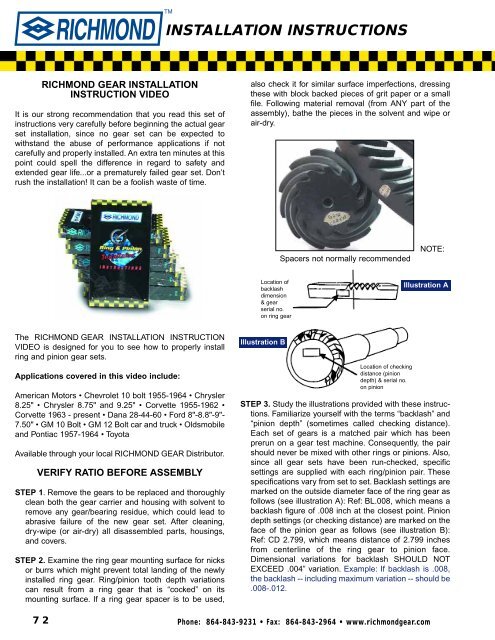
Location of<br />
backlash<br />
dimension<br />
& gear<br />
serial no.<br />
on ring gear<br />
Illustration B<br />
Spacers not normally recommended<br />
Location of checking<br />
distance (pinion<br />
depth) & serial no.<br />
on pinion<br />
NOTE:<br />
Illustration A<br />
STEP 3. Study the illustrations provided with these instructions.<br />
Familiarize yourself with the terms “backlash” and<br />
“pinion depth” (sometimes called checking distance).<br />
Each set of gears is a matched pair which has been<br />
prerun on a gear test machine. Consequently, the pair<br />
should never be mixed with other rings or pinions. Also,<br />
since all gear sets have been run-checked, specific<br />
settings are supplied with each ring/pinion pair. These<br />
specifications vary from set to set. Backlash settings are<br />
marked on the outside diameter face of the ring gear as<br />
follows (see illustration A): Ref: BL.008, which means a<br />
backlash figure of .008 inch at the closest point. <strong>Pinion</strong><br />
depth settings (or checking distance) are marked on the<br />
face of the pinion gear as follows (see illustration B):<br />
Ref: CD 2.799, which means distance of 2.799 inches<br />
from centerline of the ring gear to pinion face.<br />
Dimensional variations for backlash SHOULD NOT<br />
EXCEED .004” variation. Example: If backlash is .008,<br />
the backlash -- including maximum variation -- should be<br />
.008-.012.<br />
72 Phone: 864-843-9231 • Fax: 864-843-2964 • www.richmondgear.com
STEP 4. When installing the pinion gear you must check its<br />
depth in the housing as per the pinion depth dimension.<br />
Add or subtract pinion depth shims to arrive at the<br />
checking distance etched on the surface of the pinion<br />
face. (See illustration C.). Refer to Helpful Hints &<br />
Additions to <strong>Richmond</strong> <strong>Gear</strong> <strong>Installation</strong> <strong>Instructions</strong> on<br />
pages 3 and 4.<br />
Illustration C<br />
Checking Distance<br />
Place shims, needed<br />
to get the required<br />
pinion depth, in<br />
these locations<br />
STEP 5. Using a mew crush collar or preload shim pack,<br />
set the pinion rotating torque to 10-15 (used bearings)<br />
20-25 (new bearings) inch pounds. For oval track<br />
applications when not using a cooling pump, set at 16-<br />
17 inch pounds on new bearings and 10 inch pounds<br />
maximum on used bearings.<br />
STEP 6. After correct installation of the pinion gear,<br />
position the ring gear and check for backlash. Mount a<br />
magnetic-base dial indicator on the axle housing in such<br />
a way that the indicator plunger will be moving in a line<br />
that is tangent to rotation of the ring gear. This will<br />
provide you with a backlash reading which should<br />
conform to the figure etched on the side of the ring gear.<br />
Again, maintain a tolerance of .004 variation. Example:<br />
If backlash is .008, the backlash - including maximum<br />
variation - should be .008-.012. (Backlash is always<br />
INSTALLATION INSTRUCTIONS<br />
Checking Distance<br />
“Ford - 8 and 9”<br />
Place shims, needed<br />
to get the required<br />
pinion depth, at<br />
pinion support<br />
measured in 3 or more places equally spaced around in<br />
the ring gear.) Note: For oval track racing set BL at<br />
approximately .012-.014 inches.<br />
STEP 7. Compensation for variations in this setting can be<br />
made by side-adjustment of the ring gear. Adjusting<br />
rings or side-shim packs can be changed to bring the<br />
backlash and rotating torque figures into tolerance. (Use<br />
same torque on gear bearings as on pinion bearings.)<br />
You are now ready to check the tooth contact pattern<br />
to assure that no accidental departures from the<br />
factory-marked specifications have been made.<br />
Apply a thin coat of RICHMOND GEAR compound<br />
(“Part # 55-0001-1”) on gear teeth for best results. Tooth<br />
contact patterns should comply with those shown on<br />
next page. (Note rounded or bullet nose shape at heel end<br />
of pattern on <strong>Gear</strong> drive sides). See page 4 for patterns and<br />
additional installation hints.<br />
If the pattern is not in those approximate positions, reset<br />
the pinion depth and reset gear backlash until the<br />
patterns are closer to the above diagram. <strong>Pinion</strong> and/or<br />
gear should not be adjusted to try to achieve a deeper<br />
pattern. The length of the pattern may vary with the<br />
amount of the load applied during the check procedure.<br />
If satisfactory pattern results cannot be obtained after a<br />
reasonable adjustment, return the gear set to<br />
RICHMOND GEAR for evaluation. An accurate evaluation<br />
can not be obtained on a used set.<br />
STEP 8. Fill the gear case with sufficient amount of<br />
RICHMOND GEAR 75-140 Synthetic <strong>Gear</strong> Lube with<br />
GL 6 rating, or better and maintain the proper level at all<br />
times. Proper maintenance is a must to protect your<br />
safety and working life of your gear set. Check oil level<br />
between scheduled oil change to insure that proper oil<br />
level is maintained. Inspect vent plug to insure it is clean<br />
and operating. Inspect oil leakage, excessive heating, or<br />
any unusual noise or vibration. Note: For oval track racing,<br />
add 2 to 3 additional pts. gear lube.<br />
RICHMOND GEAR OIL<br />
75-140 Synthetic Oil.<br />
Phone: 864-843-9231 • Fax: 864-843-2964 • www.richmondgear.com<br />
GL6 with Limited Slip Additive<br />
1 U.S. Quart / 0.946 Liter<br />
73
FINAL RESULTS<br />
Properly designed, manufactured, and maintained<br />
RICHMOND GEAR gears, correctly assembled by you in a<br />
clean rigid gear box, and operated with the proper lubricant,<br />
should result in safe and satisfactory performance. Be<br />
sure you select the proper application for your gear set.<br />
Any questions concerning these installation instructions<br />
must be forwarded to us for clarification at the following<br />
address:<br />
RICHMOND GEAR<br />
P.O. Box 238, Old Norris Road<br />
Liberty, South Carolina 29657<br />
TechLine: 864-843-9275<br />
Email: tech@richmondgear.com<br />
WARRANTY<br />
Warranty is limited to material and/or workmanship defect<br />
at time of shipment from the factory, and in no event shall<br />
seller have any liability for consequential damages of any<br />
kind resulting from a breach of this warranty. This warranty<br />
will be void on all products that show evidence of<br />
misapplication, improper installation, abuse, lack of proper<br />
maintenance, negligence, or alteration from original<br />
design. This warranty is in lieu of any other warranties,<br />
either express or implied, INCLUDING ANY IMPLIED<br />
WARRANTIES OF MERCHANTABILITY OF FITNESS FOR<br />
ANY PARTICULAR PURPOSE.<br />
ADDITIONAL INFORMATION<br />
Buyer shall be solely responsible for determining the<br />
adequacy of the product for any and all uses to which buyer<br />
shall apply the product. The application by buyer shall not be<br />
subject to any implied warranty of fitness for that particular<br />
purpose. The manufacturer makes no warranty or<br />
representations, expressed or implied, by operation of law<br />
or otherwise as to the merchantability or fitness for a particular<br />
purpose of the goods sold hereunder. Buyer<br />
acknowledges that it alone has determined that the goods<br />
purchased hereunder will suitably meet the requirements of<br />
their intended use. In no event will the manufacturer be<br />
liable for consequential, incidental or other damages.<br />
These instructions do not purport to cover all details or<br />
variations in equipment, nor to provide for every possible<br />
contingency to be met in connection with selection,<br />
installation, operation, lubrication, and maintenance.<br />
Should further information be desired or should particular<br />
problems arise which are not covered sufficiently for the<br />
purchaser’s purpose, the matter should be referred to<br />
RICHMOND GEAR.<br />
INSTALLATION INSTRUCTIONS<br />
BREAK IN<br />
A new ring and pinion installation, especially a high<br />
numeric ratio with new bearings, can cause an excessive<br />
heat buildup in the rear end and cause softening of the<br />
gear teeth and bearings if a break in is not performed.<br />
Street vehicles should be driven at normal street driving<br />
speed for approximately 10 miles, then stop and let cool for<br />
30 minutes. Do this 2 to 3 times. Towing vehicles need<br />
approximately 200 to 300 miles of normal street driving<br />
before being used for towing.<br />
On circle track race cars make approximately 6 to 8 laps at<br />
slow speed, then let cool for 30 minutes. Make 6 to 8 more<br />
laps at slow speed, then 2 to 3 laps at full speed, then let<br />
cool again for 30 minutes.<br />
Drag cars need only an initial run-in since they are driven<br />
short distances and heat is not normally a problem with<br />
proper lube and backlash allowance.<br />
NOTE: If after the above break in is performed, overheating<br />
of the rear end is suspected, repeat the final portion of the<br />
break in procedures.<br />
HELPFUL HINTS & ADDITIONS TO<br />
RICHMOND GEAR<br />
INSTALLATION INSTRUCTIONS<br />
After completely reading instructions, go back to step #4.<br />
The following group of shim thickness are only if you do not<br />
have access to a pinion depth gauge or the old shim from<br />
the old pinion to start with. G.M.- .035, Ford 8-9” - .020,<br />
Ford 8.8 - 7.5 - .030, All Dana’s- .035, 8-3/4 x 1-3/4 pin, -<br />
.090, 8-3/4 x 1-7/8 pin, - .020, Mopar- 9-1/4 - .020.<br />
<strong>Pinion</strong> depth shims are located underneath the rear pinion<br />
bearing cone that is pressed on pinion with exception of the<br />
Dana Models. Dana pinion depth shims are underneath the<br />
rear pinion bearing cup in the housing. Dana carrier<br />
bearing preload shims are between carrier and bearing<br />
cone. All others are on the outside of bearing cup unless<br />
spanners are used as in the Ford 8 and 9 inch, both 8-3/4<br />
and Mopar 9-1/4. Ford 8 and 9 inch pinion depth is<br />
regulated by shims between pinion support and chuck or<br />
center section.<br />
Step #5 - If crush collar is used to set bearing preload, do<br />
not use until you have established pinion depth and<br />
backlash and you are satisfied with the pattern you get.You<br />
can simulate pinion bearing preload by tightening pinion<br />
nut until the right preload is achieved with only motor oil on<br />
the pinion bearings. The crush collar and pinion seal should<br />
be last to install.<br />
74 Phone: 864-843-9231 • Fax: 864-843-2964 • www.richmondgear.com
A<br />
B<br />
C<br />
D<br />
Heel<br />
(outer end)<br />
Heel<br />
(outer end)<br />
Heel<br />
(outer end)<br />
Heel<br />
(outer end)<br />
TORQUE SPECIFICATIONS<br />
RING GEAR BOLTS<br />
GRADE 8<br />
3/8'' x all lengths 45-50 ft lbs.<br />
7/16'' x all lengths 60-65 ft lbs.<br />
1/2'' x all lengths 100-110 ft lbs.<br />
CARRIER CAP BOLTS<br />
7/16'' (5/8'' head) 60-65 ft lbs.<br />
1/2'' (3/4'' head) 80-85 ft lbs.<br />
Step #7-G.M. rear cover style housings use shims on the<br />
outside, between bearing cup and housing, adjusting<br />
backlash and carrier bearing preload. If starting with a bare<br />
housing, or you are installing a spool or different carrier,<br />
before you mount the ring gear, establish equal shim pack<br />
on each side of carrier and enough to create a drag when<br />
you slide it in and out of the housing by hand. Keep in mind<br />
you should keep the thickest shim next to the bearing cup.<br />
With a little loctite on the threads of the ring gear bolt, mount<br />
TOOTH CONTACT CHART<br />
<strong>Ring</strong> <strong>Gear</strong> Tooth Contact Coast Side Drive Side Condition Remedy<br />
Top Land<br />
Drive<br />
Top Land<br />
Drive<br />
Top Land<br />
Drive<br />
Top Land<br />
Drive<br />
Coast<br />
Coast<br />
Coast<br />
Coast<br />
Root<br />
Toe<br />
(inner end)<br />
Root<br />
Toe<br />
(inner end)<br />
Root<br />
Toe<br />
(inner end)<br />
Root<br />
Toe<br />
(inner end)<br />
INSTALLATION INSTRUCTIONS<br />
49-Series Ideal Pattern<br />
69-79-Series Ideal Pattern<br />
All Series - Pattern Too High<br />
All Series - Pattern Too Low<br />
IDEAL<br />
PATTERN<br />
IDEAL<br />
PATTERN<br />
HIGH TOOTH<br />
CONTACT<br />
heavy on the top<br />
of the drive gear<br />
tooth profile<br />
LOW TOOTH<br />
CONTACT<br />
heavy on the<br />
root of the drive<br />
gear tooth profile<br />
gear to carrier or spool. After adjusting shim pack to get<br />
proper backlash and once you have established your<br />
pattern, remove carrier and pinion. Now is the time to install<br />
crush collar and pinion seal. NOTE: Always use loctite on<br />
the pinion nut. If you do not have a rear end housing<br />
spreader, you will have to work at installing the carrier once<br />
you add more shim to preload the carrier bearings. As a rule<br />
of thumb all carrier bearings will require .010 preload. After<br />
adding .005 to each side of the shim pack, coat surfaces of<br />
the shims with axle bearing grease to hold them in the<br />
housing, make sure the cups stay straight. Using a plastic or<br />
brass hammer, gently pound on bearing cups side to side<br />
until carrier has seated in housing. Again, it is important that<br />
you keep the cups straight during this operation. A<br />
spreader is almost necessary for all Dana Model rear ends.<br />
Torque caps to proper torque value.<br />
Phone: 864-843-9231 • Fax: 864-843-2964 • www.richmondgear.com<br />
V/A<br />
N/A<br />
Move the Drive<br />
PINION DEEP-<br />
ER<br />
into MESH.<br />
Move the Drive<br />
PINION OUT<br />
of MESH.<br />
75


