General Intermittent Sand Filters - Virginia Department of ...
General Intermittent Sand Filters - Virginia Department of ...
General Intermittent Sand Filters - Virginia Department of ...

Create successful ePaper yourself
Turn your PDF publications into a flip-book with our unique Google optimized e-Paper software.
MINIMUM STANDARD 3.12 CHAPTER 3<br />
MINIMUM STANDARD 3.12<br />
GENERAL INTERMITTENT<br />
SAND FILTERS<br />
3.12A Washington D.C. Underground Vault <strong>Sand</strong> Filter<br />
3.12B Delaware <strong>Sand</strong> Filter<br />
3.12C Austin Surface <strong>Sand</strong> Filter
MINIMUM STANDARD 3.12 CHAPTER 3
MINIMUM STANDARD 3.12 CHAPTER 3<br />
LIST OF ILLUSTRATIONS<br />
# FIGURES PAGE<br />
3.12-1 Austin Partial Sedimentation Surface <strong>Sand</strong> Filter .................... 3.12-1<br />
3.12-2 Flow Splitting Manhole Structure ............................... 3.12-11<br />
3.12-3 Degradation <strong>of</strong> Hydraulic Conductivity <strong>of</strong> Denver <strong>Sand</strong> Filter ........ 3.12-13<br />
3.12-4 Full Sedimentation Basin on Austin <strong>Sand</strong> Filter ................... 3.12-14<br />
3.12A-1 Washington D.C. Underground Vault <strong>Sand</strong> Filter .................. 3.12A-2<br />
3.12A-2 Washington D.C. <strong>Sand</strong> Filter Cross-Section ....................... 3.12A-5<br />
3.12A-3 Dimensional Relationship for a D.C. <strong>Sand</strong> Filter .................. 3.12A-10<br />
3.12A-4 Installing Precast D.C. <strong>Sand</strong> Filter Shell in Alexandria ............. 3.12A-13<br />
3.12A-5 D.C. <strong>Sand</strong> Filter Cross-Section with HDPE Infiltration Chamber<br />
Collection System .......................................... 3.12A-14<br />
3.12B-1 Precast Delaware <strong>Sand</strong> Filter as Used in <strong>Virginia</strong> .................. 3.12B-2<br />
3.12B-2 Dimensional Relationships for Delaware <strong>Sand</strong> Filter ............... 3.12B-5<br />
3.12B-3 Installing Precast Delaware <strong>Sand</strong> Filter Shell in Alexandria .......... 3.12B-13<br />
3.12C-1 Austin Full Sedimentation <strong>Sand</strong> Filter at Barton Ridge Plaza ......... 3.12C-2<br />
3.12C-2 Sedimentation Basin <strong>of</strong> Jolleyville Partial Sedimentation System ...... 3.12C-3<br />
3.12C-3 Underground Vault Fabricated from Precast Bridge Arch Components . 3.12C-5<br />
3.12C-4 Riser Pipe Detail for Full Sedimentation Basin ................... 3.12C-14<br />
3.12C-5 Austin <strong>Sand</strong> Filter Cross-Section with Filter Fabric Layer .......... 3.12C-15<br />
3.12C-6 Partial Sedimentation Vault Filter with Pea Gravel Layer ........... 3.12C-16<br />
3.12C-7 Restrictive Orifice Access Manhole ............................ 3.12C-19<br />
3.12-i
MINIMUM STANDARD 3.12 CHAPTER 3<br />
LIST OF ILLUSTRATIONS cont.<br />
# TABLES PAGE<br />
3.12-1 Pollutant Removal Efficiency for Intermittant <strong>Sand</strong> Filter Facilities ..... 3.12-2<br />
3.12-2 Pollutant Removal Efficiencies for a Delaware <strong>Sand</strong> Filter in Alexandria . 3.12-3<br />
3.12-3 Appropriate Intermittant <strong>Sand</strong> Filter Applications to Various Site Areas . 3.12-6<br />
3.12-4 Percent <strong>of</strong> Street Pollutants in Various Particle Size Ranges ........... 3.12-9<br />
3.12A-1 Specifications for Nonwoven Geotextile Fabric on Top <strong>of</strong> D.C.<br />
<strong>Sand</strong> Filter ................................................. 3.12A-7<br />
3.12A-2 Specifications for Nonwoven Geotextile Fabric beneath the <strong>Sand</strong><br />
in a D.C. <strong>Sand</strong> Filter ......................................... 3.12A-7<br />
3.12B-1 Specifications for Nonwoven Geotextile Fabric on Top <strong>of</strong> Delaware<br />
<strong>Sand</strong> Filter ................................................. 3.12B-7<br />
3.12B-2 Specifications for Nonwoven Geotextile Fabric Beneath <strong>Sand</strong> in<br />
Delaware <strong>Sand</strong> Filter ........................................ 3.12B-7<br />
3.12C-1 Cost <strong>of</strong> Austin <strong>Sand</strong> Filtration Systems .......................... 3.12C-4<br />
3.12C-2 Clay Liner Specifications .................................... 3.12C-11<br />
3.12C-3 Geotextile Specifications for Basin Liner <strong>Sand</strong>wich ................ 3.12C-12<br />
3.12C-4 Perforated Riser Pipes ....................................... 3.12C-13<br />
3.12C-5 Specifications for Nonwoven Geotextile Fabric Beneath <strong>Sand</strong> in<br />
Austin <strong>Sand</strong> Filter .......................................... 3.12C-14<br />
3.12-ii
MINIMUM STANDARD 3.12 CHAPTER 3<br />
MINIMUM STANDARD 3.12<br />
GENERAL INTERMITTENT SAND FILTER PRACTICES<br />
Definition<br />
<strong>Intermittent</strong> sand filter facilities capture, pretreat to remove sediments, store while awaiting<br />
treatment, and treat to remove pollutants (by percolation through sand media) the most polluted<br />
stormwater (the water quality volume) from a site. <strong>Intermittent</strong> sand filter BMPs may be constructed<br />
in underground vaults, in paved trenches within or at the perimeter <strong>of</strong> impervious surfaces, or in<br />
either earthen or concrete open basins. They have been successfully used in Austin Texas, the<br />
District <strong>of</strong> Columbia, The State <strong>of</strong> Delaware, and in Alexandria, <strong>Virginia</strong> over the last two decades.<br />
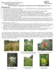
Figure 3.12-1 is a photograph <strong>of</strong> a sand filter BMP in Austin.<br />
FIGURE 3.12 - 1<br />
Austin Partial Sedimentation Surface <strong>Sand</strong> Filter<br />
(Photo Courtesy <strong>of</strong> City <strong>of</strong> Austin, Texas)<br />
3.12-1
MINIMUM STANDARD 3.12 CHAPTER 3<br />
Purpose<br />
<strong>Intermittent</strong> sand filter facilities are primarily used for water quality control. However, they do<br />
provide detention and slow release <strong>of</strong> the water quality volume from the site being treated. Whether<br />
this amount will be sufficient to provide the necessary peak flow rate reductions required for channel<br />
erosion control is dependent upon site conditions (hydrology) and required discharge reductions.<br />
The 10-year and 100-year flows will usually exceed the detention capacity <strong>of</strong> a sand media filter.<br />
When this occurs, separate quantity facilities must be provided. Table 3.12-1 contains the target<br />
removal efficiencies <strong>of</strong> sand and other soil media filter BMPs. Table 3.12-2 contains the results <strong>of</strong><br />
an extensive sand filter monitoring study in Alexandria conducted for the Chesapeake Bay Local<br />
Assistance <strong>Department</strong> (Bell, Stokes, Gavan, and Nguyen, 1995).<br />
TABLE 3.12-1<br />
Pollutant Removal Efficiency for <strong>Intermittent</strong> <strong>Sand</strong> Filter Facilities<br />
BMP Description<br />
<strong>Intermittent</strong> <strong>Sand</strong> Filter treating 0.5 inches <strong>of</strong> run<strong>of</strong>f from<br />
the impervious area.<br />
Pollutant Removal Mechanisms at Work in <strong>Intermittent</strong> <strong>Sand</strong> Filter BMPs<br />
3.12-2<br />
Target Phosphorus<br />
Removal Efficiency<br />
Pollutant removal processes at work in intermittent sand filters are complex and involve<br />
physical, chemical, and biological transformations (Tchobanoglous and Burton, 1991;<br />
Anderson, Siegrist, and Otis, Undated). The most obvious mechanism is physical straining<br />
<strong>of</strong> suspended solids and particulate nutrients.<br />
Suspended Solids<br />
Mechanical straining, straining due to chance contact, and sedimentation are the principal<br />
mechanisms by which suspended solids are removed, although the growth <strong>of</strong> bacterial colonies<br />
within the sand grains may also cause aut<strong>of</strong>iltration (Tchobanoglous and Burton, 1991).<br />
65%
MINIMUM STANDARD 3.12 CHAPTER 3<br />
Table 3.12-2<br />
Pollutant Removal Efficiencies for a Delaware <strong>Sand</strong> Filter in Alexandria<br />
Constituent<br />
3.12-3<br />
Mass Balance Removal<br />
Efficiency<br />
(%)<br />
Cadmium NA<br />
Copper NA<br />
Zinc >90.7<br />
Iron NA<br />
Ammonia Nitrogen >39.0<br />
Nitrite Nitrogen >45.8<br />
Nitrate Nitrogen -62.7<br />
NO x<br />
-53.3<br />
Total Kjeldahl Nitrogen 70.6<br />
Total Phosphorous 63.1/72.3 1<br />
Ortho-Phosphorous >68.3/74.4 1<br />
Total Suspended Solids >78.8/>83.9 2<br />
Hardness 38.5<br />
Biochemical Oxygen Demand (5 Day) >77.5<br />
Total Petroleum Hydrocarbons >84 3<br />
Total Organic Carbon 65.9<br />
1 Excluding Anaerobic Incident Data 2 Excluding Storms with Heavy Iron Export<br />
3 Average Removal from Alaska Marine Lines Filter 3 in Seattle, Washington (Horner,1995)<br />
Phosphorous<br />
Phosphorous removal is performed by physiochemical processes such as mechanical and<br />
chance contact straining, precipitation, and adsorption (Piluk and Hao, 1989; Laak, 1986).<br />
There are three general types <strong>of</strong> adsorption (the condensation and concentration <strong>of</strong> ions or<br />
molecules <strong>of</strong> one material [the adsorbate] on the surface <strong>of</strong> another [the adsorbent]): physical,
MINIMUM STANDARD 3.12 CHAPTER 3<br />
chemical, and exchange. Physical adsorption results from the weak forces <strong>of</strong> attraction between<br />
molecules and is generally quite reversible. Chemical adsorption results from much stronger<br />
forces comparable to those leading to the formation <strong>of</strong> chemical compounds, with the adsorbed<br />
material forming a one molecule thick layer over the surface <strong>of</strong> the absorbent until the capacity<br />
<strong>of</strong> the absorbent is exhausted. Chemical adsorption is seldom reversible. Exchange adsorption, on<br />
the other hand, results from electrical attraction between the adsorbate and the surface, such as<br />
occurs with ion exchange. Ions <strong>of</strong> the adsorbate concentrate on the surface <strong>of</strong> the adsorbent as<br />
a result <strong>of</strong> electrical attraction to opposite charges on the surface. It is sometimes difficult to assign<br />
a given adsorption to a specific type (Sawyer, Mcarty, and Parkin, 1994).<br />
Although exchange adsorption may also be involved, most adsorption in intermittent sand filters<br />
appears to be chemical adsorption (Piluk and Hao, 1989; Otis, Undated; Anderson, Siegrist,<br />
and Otis, Undated).<br />
In addition to the filter mass available, the adsorption <strong>of</strong> phosphorous in sand filters is also<br />
affected by the pH <strong>of</strong> the material being filtered (with higher removal rates occurring with the<br />
reduction <strong>of</strong> pH), temperature, contact time, and the character <strong>of</strong> the filter media (Laak, 1986).<br />
<strong>Sand</strong>s containing iron, aluminum, or calcium have a higher phosphorous removal potential because<br />
phosphorous will combine with these elements through chemical precipitation and become relatively<br />
insoluble (Laak, 1986, Tchobanoglous and Burton, 1991). If the filter becomes anaerobic, the<br />
bonding with iron may break down, releasing orthophosphates (Harper and Herr, 1993). However,<br />
aerobic filters enriched with iron may attain almost complete phosphorous removal until the filter<br />
capacity is exhausted, and properly sized filters may have a life <strong>of</strong> up to 20 years (Laak, 1986).<br />
<strong>Sand</strong> particles with sufficient iron content may become positively charged, leading to more<br />
favorable medium-particle interactions and increased removal rates (Stenkamp and Benjamin, 1994).<br />
Entrapment in the filter <strong>of</strong> a high percentage <strong>of</strong> the iron in the run<strong>of</strong>f being treated may provide a<br />
source to replenish used up phosphorous adsorption capacity.<br />
Nitrogen and Biochemical Oxygen Demand<br />
Mineralization <strong>of</strong> organic nitrogen into ammonium (NH +<br />
4) may occur under either aerobic or<br />
anaerobic conditions if the required naturally occurring chemoautotrophic bacteria (organisms<br />
which obtain energy by oxidizing simple chemical compounds) are present (Nitrosomonas,<br />
Nitrosococcus, Nitrospira, Nitrosolobus, Nitrososovibrio) ((Laak, 1986; The Cadmus Group, 1991).<br />
+<br />
Organic N 6 Bacterial enzymes 6 NH4 + other products<br />
Positively charged ammonium ions are then adsorbed to negatively charged sand filter<br />
particles through exchange adsorption (The Cadmus Group, 1991).<br />
The transformation <strong>of</strong> ammonia (NH 3) and ammonium into nitrite and nitrate (NO 2<br />
- and NO3<br />
- )<br />
and the removal <strong>of</strong> BOD 5 occur under aerobic conditions by microorganisms (such as Nitrosomonas<br />
and Nitrobacter) present in the sand bed (Tchobanoglous and Burton, 1991;, Laak, 1991; The<br />
Cadmus Group, 1991).<br />
3.12-4
MINIMUM STANDARD 3.12 CHAPTER 3<br />
+ - NH4 + 1.5O2 6 Nitrosomonas, etc 6 NO2 + 2H + H2O + Energy<br />
- -<br />
NO2 + 0.5O2 6 Nitrobacter 6 NO3 + Energy<br />
Since nitrite and nitrate are soluble anions, they are not affected by the cation exchange complex<br />
<strong>of</strong> the filter, but rather tend to leach readily to the filter effluent (Gold, Lamb, Loomis, and McKiel,<br />
Undated). However, anaerobic microenvironments (sometimes called "microsites") routinely<br />
coexist in principally aerobic intermittent sand filters (Tchobanoglous and Burton,1991; Gold,<br />
Lamb, Loomis, and McKiel, Undated). Naturally occurring anaerobic bacteria<br />
(Pseudomonas, Micrococcus, Achromobacter, Bacilluss) in these pockets may convert much <strong>of</strong><br />
the nitrite into nitrate and the nitrate to nitrogen gas, resulting in total nitrogen removal in<br />
intermittent sand filters ranging up to 45-50 percent (Tchobanoglous and Burton, 1991; Laak,<br />
1986; Ronayne, Paeth, and Osborne, Undated).<br />
-<br />
NO3 + Organic Carbon 6 Denitrifying 6 N2 + H2O + CO2 + Cells<br />
bacteria<br />
Organic carbon must be present for denitrification to occur, but low organic carbon/nitrogen rations<br />
will suffice (1:2 or less) (Laak, 1986, p.62). Some studies indicate that optimal denitrification<br />
occurs at ratios <strong>of</strong> 1:1-3:1 (Gold, et al, p.298). The maximum rate <strong>of</strong> denitrification occurs at<br />
temperatures above 10 degrees C and at a pH above 5.5, with the optimum pH range falling<br />
between 7.0 and 8.0. (The Cadmus Group, 1991, p.11). However, home wastewater systems<br />
have demonstrated excellent denitrification performance when the wastewater temperature<br />
was as low as 4 degrees C (Piluk and Hoa, 1989).<br />
Heavy Metals<br />
More than 70 percent <strong>of</strong> heavy metals in stormwater run<strong>of</strong>f is in particulate form (Harper and Herr,<br />
1993). Over 70 percent <strong>of</strong> particulate heavy metals are <strong>of</strong> greater than 104 microns in size (Shaver<br />
and Baldwin, 1990). Particle settling in presettling basins and mechanical straining appear to<br />
be the principal mechanism for removing heavy metals in stormwater intermittent sand filter<br />
systems. Some iron may be removed by reacting with phosphorous in the run<strong>of</strong>f being treated.<br />
Hydrocarbons<br />
Mechanical straining and physical adsorption appear to be the mechanisms removing<br />
hydrocarbons which reach the sand filter.<br />
3.12-5
MINIMUM STANDARD 3.12 CHAPTER 3<br />
Conditions Where Practice Applies<br />
<strong>Intermittent</strong> sand filters are suitable for use in ultra-urban settings with a high degree <strong>of</strong><br />
imperviousness where the land cost or loss <strong>of</strong> economic return on real estate required to construct<br />
retention basins may be prohibitive. They are generally suited for high pollutant removal on<br />
medium to high density development (65 to 100% impervious cover). Specific conditions such as<br />
drainage area size and development conditions are discussed with each type <strong>of</strong> intermittent sand<br />
filter. Because they are subject to failure by clogging, intermittent sand filters are not recommended<br />
for use on watersheds where sediment loadings can be significant. Wherever possible, their use<br />
should be limited to treating run<strong>of</strong>f from impervious surfaces. Most <strong>of</strong> the practices discussed<br />
below are designed to treat run<strong>of</strong>f from watersheds with at least 65% impervious cover. Where<br />
other run<strong>of</strong>f must be treated, sediment protection must be increased to severely curtail the sediment<br />
load reaching the filter media.<br />
Site Conditions<br />
1. Size and Topography <strong>of</strong> the Site<br />
Planning Considerations<br />
Some types <strong>of</strong> intermittent sand filter BMPs are especially suited to larger drainage sheds, while<br />
others have upper size limits on their effective use. Table 3.12-3 outlines drainage shed size<br />
applications <strong>of</strong> various types <strong>of</strong> intermittent sand filter facilities. On larger sites with multiple<br />
drainage sheds, a variety <strong>of</strong> BMPs might prove to be most cost effective.<br />
TABLE 3.12 - 3<br />
Appropriate <strong>Intermittent</strong> <strong>Sand</strong> Filter Applications to Various Site Areas<br />
Type <strong>of</strong> <strong>Intermittent</strong> <strong>Sand</strong> Filter Appropriate Drainage Shed to filter<br />
District <strong>of</strong> Columbia Underground Vault <strong>Sand</strong> <strong>Filters</strong> Medium (0.25-1.25 impervious acres)<br />
Delaware <strong>Sand</strong> <strong>Filters</strong> Small-Medium (< 1.25 impervious acres)<br />
Austin Full Sedimentation <strong>Sand</strong> <strong>Filters</strong> (Surface or Vault) Large (> 1.25 impervious acres)<br />
Austin Partial Sedimentation <strong>Sand</strong> <strong>Filters</strong> (Surface) Medium-Large<br />
Austin Partial Sedimentation <strong>Sand</strong> <strong>Filters</strong> (Underground) Medium<br />
3.12-6
MINIMUM STANDARD 3.12 CHAPTER 3<br />
2. Stormwater Infrastructure Serving Site<br />
Both the size and the elevations <strong>of</strong> stormwater infrastructure serving the site as a whole are<br />
important considerations. A critically important design parameter is the potential difference in<br />
elevation <strong>of</strong> the receiving manhole in the stormwater infrastructure and the elevation <strong>of</strong> the closest<br />
manhole in the new storm sewer system draining the site to be served. This will determine the<br />
depth <strong>of</strong> water than can be pooled above the filter media with the system operating on gravity flow.<br />
Almost all intermittent sand filter BMPs are designed to flow by gravity. However, in commercial<br />
and industrial applications where dedicated maintenance crews with familiarity with mechanical<br />
equipment will be available, pumped flow should be considered a viable alternative.<br />
3. Depth to Seasonally High Groundwater Table<br />
The liner or concrete shell <strong>of</strong> intermittent sand filter BMPs is usually placed at least 2 to 4 feet above<br />
the seasonally high water table or bedrock in order to assure dry conditions for construction and to<br />
minimize infiltration <strong>of</strong> groundwater into the filter structure. However, in some cases, it may be<br />
economical and practical to place filter shells below the seasonally high water table. In such cases,<br />
floatation effects must be countered by providing extra weight or hold down components in the filter<br />
shell.<br />
4. Value <strong>of</strong> the Real Estate and Expected Income from Development<br />
The value <strong>of</strong> real estate in highly urbanized areas may drive the overall cost <strong>of</strong> traditional structural<br />
BMPs too high for serious consideration. In Alexandria, for example, the cost <strong>of</strong> real estate alone<br />
to construct retention ponds averages $60,000 per impervious acre treated, while the cost <strong>of</strong> real<br />
estate for extended detention basins averages $40,000 per impervious acre treated. The overall<br />
costs <strong>of</strong> underground vault sand filters, which may be placed under parking lots and private streets<br />
or even within building structures and therefore have no real estate cost, can become quite<br />
competitive under such circumstances. The income stream from increased development allowed<br />
by underground BMPs should also be considered in such analyses.<br />
5. Aesthetic and Land Use Considerations<br />
Most traditional stormwater BMPs may be severely lacking in visual attractiveness. This may be<br />
especially true with some extended detention basins and retention basins lacking a base flow to<br />
prevent eutrophication during hot, dry weather. Questions also <strong>of</strong>ten arise about the use <strong>of</strong><br />
valuable open space on projects for BMPs instead <strong>of</strong> alternative uses such as recreation. Most sand<br />
filter BMPs are visually unobtrusive and may be used in situations where aesthetic considerations<br />
or open space use are important.<br />
3.12-7
MINIMUM STANDARD 3.12 CHAPTER 3<br />
Sediment Control<br />
<strong>Intermittent</strong> sand filter BMPs which have been subjected to heavy sediment loadings have<br />
historically failed very quickly (LaRock, 1988; Harper and Herr, 1993). In a study in Denver,<br />
Colorado, Urbonis, Doerfer, and Tucket found that the hydraulic conductivity <strong>of</strong> a sand filter serving<br />
an equipment parking lot dropped rapidly as sediment accumulated on the surface <strong>of</strong> the filter<br />
(Urbonis, Doerfer, and Tucker, 1996) . A layer <strong>of</strong> sediment approximately 1/16 inch (1.6<br />
millimeters) thick was found to limit hydraulic conductivity to 0.05 feet per hour (1.6 ft/day),<br />
considerably less than the design coefficient <strong>of</strong> permeability used by Northern <strong>Virginia</strong> jurisdictions<br />
in the design <strong>of</strong> sand filters (ibid.; Bell, Stokes, Gavan, and Nguyen, 1995). The filter media <strong>of</strong><br />
intermittent sand filter BMPs must therefore be protected from excessive sediment loads. This<br />
requires isolation during construction <strong>of</strong> the development, site design to restrict the amount <strong>of</strong> run<strong>of</strong>f<br />
from pervious areas reaching the filter after construction, and proper sizing <strong>of</strong> sediment removing<br />
features <strong>of</strong> the BMP to match final site conditions.<br />
1. Construction Run<strong>of</strong>f<br />
<strong>Sand</strong> filter BMPS must never be placed in service until all site work has been completed and<br />
stabilization measures have been installed and are functioning properly.<br />
When this precaution has not been taken in the past, the sand filter BMPs have become clogged with<br />
sediment from upland construction operations almost immediately, requiring complete<br />
reconstruction <strong>of</strong> the sand filter and sometimes the collector pipe system. This can prove very<br />
expensive. However, since most sand filter BMPs are constructed <strong>of</strong>f-line with a flow splitting<br />
device employed to divert only the Water Quality Volume to the filter, the BMP may usually be<br />
completely constructed but isolated from run<strong>of</strong>f by blocking the inflow pipe until the site is fully<br />
stabilized.<br />
2. Urban Run<strong>of</strong>f<br />
While experience indicates that intermittent sand filters fail very quickly when directly exposed<br />
to run<strong>of</strong>f from watersheds with low imperviousness and poor vegetated cover (LaRock,<br />
1988; Harper and Herr, 1993), filters which treat run<strong>of</strong>f from almost exclusively impervious<br />
areas, such as highway surfaces, may perform satisfactorily for several years with very little<br />
maintenance (Shaver and Baldwin, 1991).<br />
An 18-month, comprehensive study <strong>of</strong> run<strong>of</strong>f from street surfaces in 12 cities throughout the U.S.<br />
determined that, while most particulate matter is in the fractions equating to sand and gravel,<br />
the approximately 6 percent <strong>of</strong> particles in the silt and clay soil size contain over half the<br />
phosphorous and some 25 percent <strong>of</strong> other pollutants (Sartor, Boyd, and Agardy, 1974). Table<br />
3.12-4 illustrates this finding.<br />
In planning the layout for a site on which sand filter BMPs are to be employed, care should be taken<br />
to direct only run<strong>of</strong>f from impervious surfaces to the filter ins<strong>of</strong>ar as possible. The drainage sheds<br />
feeding sand filter BMPs with only partial sediment protection (as delineated in the individual BMP<br />
3.12-8
MINIMUM STANDARD 3.12 CHAPTER 3<br />
discussions which follow) should never contain less than 65% impervious cover. Even when full<br />
sediment protection is provided in the form <strong>of</strong> a carefully sized presettlement basin, the amount <strong>of</strong><br />
run<strong>of</strong>f from pervious areas directed to the filter must be minimized. The Denver study also<br />
indicates that full sediment protection may be required in areas subject to heavy atmospheric<br />
deposition <strong>of</strong> suspended solids even when only run<strong>of</strong>f from impervious surfaces is being treated.<br />
The presettling basin or sedimentation chamber <strong>of</strong> an intermittent sand filter BMP is expected to<br />
remove all but the very fine particles <strong>of</strong> sediment, while most <strong>of</strong> the other pollutant removal is<br />
expected to occur in the sand filter, where the very fine particles will be trapped.<br />
TABLE 3.12-4<br />
Percent <strong>of</strong> Street Pollutants in Various Particle Size Ranges<br />
Particle Size (Microns)<br />
Pollutant >2000 840-2000 246-840 104-246 43-104
MINIMUM STANDARD 3.12 CHAPTER 3<br />
Maintenance<br />
The maintenance requirements for intermittent sand filters must be considered during the planning<br />
and design <strong>of</strong> the facility. All chambers <strong>of</strong> underground sand filters must have personnel access<br />
manholes and built-in access ladders . Access roads or streets must be <strong>of</strong> sufficient width and<br />
bearing capacity to support dump trucks loaded with accumulated sediments or heavy vacuum<br />
(e.g.”VACTOR”) trucks for removing accumulated sediments and hydrocarbons from sediment<br />
chambers and traps on a regular basis. Approximately every 3-5 years, the filter can be expected<br />
to clog to the point that replacement <strong>of</strong> the top few inches <strong>of</strong> sand or, where employed, the layer <strong>of</strong><br />
washed gravel and the top layer <strong>of</strong> filter cloth will be required. A minimum maintenance<br />
headspace <strong>of</strong> 60 inches above the filter is required in underground vault filters BMPs. A<br />
36-38-inch diameter maintenance manhole with a small, concentric personnel access lid or a<br />
rectangular load bearing access door (minimum 4 ft. x 4 ft.) should be positioned directly over the<br />
center <strong>of</strong> the filter. Large sedimentation basins and open filters must be equipped with access ramps<br />
to allow small earthmoving equipment such as “Bobcats” and light trash raking equipment to go into<br />
the basins. Finally, before finalizing the BMP design, follow the advice <strong>of</strong> Joseph J. Skupien,<br />
Principal Hydraulic Engineer <strong>of</strong> Somerset County, New Jersey, and “close your eyes, kick back, and<br />
think your BMP through a full year <strong>of</strong> operations, visualizing how it will perform under the<br />
conditions <strong>of</strong> all four seasons.”<br />
<strong>General</strong> Design Criteria<br />
The purpose <strong>of</strong> this section is to provide recommendations and minimum criteria for the design <strong>of</strong><br />
intermittent sand filter practices intended to comply with the <strong>Virginia</strong> Stormwater Management<br />
program’s run<strong>of</strong>f quality requirements.<br />
Several types <strong>of</strong> intermittent sand filter facilities are recognized for stormwater quality management<br />
purposes, including District <strong>of</strong> Columbia Underground Vault <strong>Filters</strong>, Delaware <strong>Sand</strong> <strong>Filters</strong>,<br />
Austin Full Sedimentation <strong>Sand</strong> <strong>Filters</strong>, and Austin Partial Sedimentation <strong>Sand</strong> <strong>Filters</strong>.<br />
The general design criteria presented below apply to the design <strong>of</strong> intermittent sand filter facilities<br />
for water quality control. This implies that the volume <strong>of</strong> run<strong>of</strong>f to be treated is determined by the<br />
water quality volume (the first 0.5 inches <strong>of</strong> run<strong>of</strong>f from the impervious surfaces on the site or<br />
drainage shed) and the desired pollutant removal efficiency.<br />
Isolating the Water Quality Volume<br />
The usual method for isolating the WQV is to construct an isolation/diversion weir in the<br />
stormwater channel or pipe, with the elevation <strong>of</strong> the weir set to allow overflow when the BMP<br />
is completely full. Additional run<strong>of</strong>f greater than the WQV spills over the weir to enter a peak flow<br />
rate reducer or exit directly to the storm sewer, minimizing mixing with the water in the BMP.<br />
Another approach is to provide a lower pipe to feed the filter until it fills, after which water rises in<br />
the slitter manhole and continues down a higher pipe. Figure 3.12 - 2 illustrates this approach<br />
(source: Montgomery County, Maryland).<br />
3.12-10
MINIMUM STANDARD 3.12 CHAPTER 3<br />
Sizing Procedure<br />
FIGURE 3.12 - 2<br />
Flow Splitting Manhole Structure<br />
The majority <strong>of</strong> jurisdictions which are employing sand filter BMPs use hydraulic calculations based<br />
on Darcy's Law to establish the filter area that will allow flow-through <strong>of</strong> the treatment volume<br />
within the desired time frame, typically 40-48 hours (Austin, 1988, Shaver and Baldwin, 1991,<br />
Truong, 1989). Florida uses more complex falling-head computations and allows a drawdown time<br />
<strong>of</strong> up to 72 hours (Livingston, McCarron, Cox, and Sanzone, 1988). However, creating storage for<br />
the full WQV in shallow configuration systems may result in a larger filter than the hydraulic<br />
calculations would indicate (Alexandria, 1992).<br />
<strong>Virginia</strong> uses the Austin <strong>Sand</strong> Filter Formula derived from Darcy's Law by the Austin<br />
Environmental and Conservation Services <strong>Department</strong> to size sand filters (Austin, 1988):<br />
A f = I aHd f / k(h+d f)t f where,<br />
A f = surface area <strong>of</strong> sand bed (acres or sq. ft.)<br />
I a = impervious drainage area contributing run<strong>of</strong>f to the basin (acres or sq. ft.)<br />
H = run<strong>of</strong>f depth to be treated (ft.)<br />
d f = sand bed depth (ft.)<br />
k = coefficient <strong>of</strong> permeability for sand filter (ft/hr)<br />
3.12-11
MINIMUM STANDARD 3.12 CHAPTER 3<br />
h = average depth (ft.) <strong>of</strong> water above surface <strong>of</strong> sand<br />
media between full and empty basin conditions (½ max. depth)<br />
t f = time required for run<strong>of</strong>f volume to pass through filter media (hrs.)<br />
1. Coefficient <strong>of</strong> Permeability<br />
When first installed, the coefficient <strong>of</strong> permeability <strong>of</strong> sand filters may be as high as 3.0 ft/hour, but<br />
these will typically decrease dramatically after the first few storms. Actual observations <strong>of</strong> filters<br />
in Austin, Texas, established that “ripe” filters stabilized in the range <strong>of</strong> 0.5-2.7 ft/day for filters with<br />
partial sedimentation control (Austin, 1988). This is probably caused by a combination <strong>of</strong> clogging<br />
<strong>of</strong> some filter pores from sediment loads and initial consolidation <strong>of</strong> the filter sand. Figure 3.12 -<br />
3 illustrates the similar rapid decrease in coefficient <strong>of</strong> permeability as sediment loads accumulated<br />
on a sand filter in Denver, Colorado (Urbonas, Doerfer, and Tucker, 1996). Falling head tests on<br />
a one year old Delaware <strong>Sand</strong> Filter in Alexandria, <strong>Virginia</strong>, resulted in an average coefficient <strong>of</strong><br />
permeability <strong>of</strong> 8.5 ft/day (Bell, Stokes, Gavan, and Nguyen, 1995). The Alexandria filter was<br />
treating only run<strong>of</strong>f from pavement surfaces, and the mean input concentration <strong>of</strong> total suspended<br />
solids was only in the range <strong>of</strong> 75 milligrams/liter (75ppm)(ibid). The Denver run<strong>of</strong>f, by contrast,<br />
had a mean concentration <strong>of</strong> 400 ppm (Urbonas, Doerfer, and Tucker, 1996), while the filters<br />
observed by Austin lacked full sedimentation protection. Use <strong>of</strong> conservative values for the<br />
coefficient <strong>of</strong> permeability is clearly indicated.<br />
Based on long term observation <strong>of</strong> existing sand filter basins, Austin uses k values <strong>of</strong> 3.5 feet per<br />
day for systems with full sedimentation pretreatment and 2.0 feet per day for systems with only<br />
partial sedimentation pretreatment (full sedimentation pretreatment is defined as complete removal<br />
<strong>of</strong> particles with a diameter equal to or greater than 20 microns). <strong>Virginia</strong> jurisdictions utilizing<br />
intermittent sand filter BMPs have also adopted these values. Full sedimentation may usually be<br />
accomplished by capturing the WQV and releasing it to the filter over 24 hours. Figure 3.12-4<br />
illistrates a full sedimentation basin in Austin. Partial sedmientation basins, such as the one shown<br />
on Figure 3.12-1, should hold at least 20 percent <strong>of</strong> the WQV.<br />
2. Drawdown time<br />
Both Austin and the <strong>Virginia</strong> jurisdictions employ a BMP drawdown time (t f) <strong>of</strong> 40 hours. This<br />
allows the filter to fully drain down and dry out to maintain an aerobic environment between storms<br />
(filters which remain continually wet may develop anaerobic conditions, under which previously<br />
captured iron phosphates may break down and wash out).<br />
3. Simplified Filter Formula for <strong>Filters</strong> with Full Sedimentation Protection<br />
(Sedimentation Basin containing full WQV with 24-hour drawdown to filter)<br />
With k = 3.5 ft/day (0.146 ft/hour) and t f = 40 hours, the sand filter formula reduces to:<br />
A f(FS) = 310I ad f / (h + d f)<br />
where A f is in ft 2 and I a is in acres.<br />
3.12-12
MINIMUM STANDARD 3.12 CHAPTER 3<br />
FIGURE 3.12-3<br />
Degradation <strong>of</strong> Hydraulic Conductivity <strong>of</strong> Denver <strong>Sand</strong> Filter<br />
(Source: Urbonas, Doeffler, and Tucker, 1996)<br />
4. Simplified Filter Formula for <strong>Filters</strong> with Partial Sedimentation Protection<br />
(Sediment Chamber containing 20% <strong>of</strong> WQV with free hydraulic flow to filter)<br />
With k = 2.0 ft/day (.0833 ft/hour) and t f = 40 hours, the formula reduces to:<br />
A f(PS) = 545I ad f / (h + d f)<br />
where A f is in ft 2 and I a is in acres.<br />
FIGURE 3.12-4<br />
3.12-13
MINIMUM STANDARD 3.12 CHAPTER 3<br />
Full Sedimentation Basin on Austin <strong>Sand</strong> Filter<br />
Exclusion <strong>of</strong> Continuous Flows and Chloronated Flows<br />
<strong>Intermittent</strong> sand filter BMPs will NOT function properly if subjected to continuous or frequent<br />
flows. The basic principles upon which they operate assume that the sand filter will dry out and<br />
reaerate between storms. If the sand is kept continually wet by such flows as basement sump pumps,<br />
anaerobic conditions will develop, creating a situation under which previously captured iron<br />
phosphates degrade, leading to export <strong>of</strong> phosphates rather than the intended high phosphorous<br />
removal (Bell, Stokes, Gavan, and Nguyen, 1995). It is also essential to exclude flows containing<br />
chlorine and other swimming pool and sauna chemicals since these will kill the bacteria upon<br />
which the principle nitrogen removal mechanisms depend.<br />
Continuous or frequent flows (such as basement sump pump discharges, cooling<br />
water,condensate water, ariesian wells, etc.) and flows containing swimming pool and<br />
sauna chemiclals must be EXCLUDED from routing through intermittent sand filter<br />
BMPs since such flows will cause the BMP to MALFUNCTION!<br />
3.12-14
MINIMUM STANDARD 3.12 CHAPTER 3<br />
Checklists<br />
The Construction Inspection and As-Built Survey Checklist found in Appendix 3D is for use in<br />
inspecting intermittent sand filter facilities during construction and, where required by the local<br />
jurisdiction, engineering certification <strong>of</strong> the filter construction. The Operation and Maintenance<br />
Checklist, also found in Appendix 3D, is for use in conducting maintenance inspections <strong>of</strong><br />
intermittent sand filter facilities.<br />
3.12-15<br />
.
MINIMUM STANDARD 3.12 CHAPTER 3<br />
MINIMUM STANDARD 3.12A<br />
WASHINGTON D.C. UNDERGROUND VAULT SAND FILTER<br />
(WET SEDIMENTATION CHAMBER)<br />
Definition<br />
A Washington D.C. vault sand filter is an underground stormwater sand filter contained in a<br />
structural shell with three chambers. The shell may be either precast or cast-in-place concrete,<br />
corrugated metal pipe, or fiberglass tanks. This BMP was developed by Mr. Hung V. Truong <strong>of</strong> the<br />
D.C. Environmental Regulation Administration. Figure 3.12A-1 depicts Mr. Truong's system.<br />
The three feet deep plunge pool in the first chamber and the throat <strong>of</strong> the second chamber, which are<br />
hydraulically connected by an underwater rectangular opening, absorbs energy and provides<br />
pretreatment, trapping grit and floating organic material such as oil, grease, and tree leaves.<br />
The second chamber also contains a typical intermittent sand filter. The filter material consists <strong>of</strong><br />
gravel, sand, and filter fabric. At the bottom is a subsurface drainage system <strong>of</strong> pierced PVC pipe<br />
in a gravel bed. The primary filter media is 18-24 inches <strong>of</strong> sand. A layer <strong>of</strong> plastic reinforced<br />
geotextile filter cloth secured by gravel ballast is placed on top <strong>of</strong> the sand. The top filter cloth is<br />
a pre-planned failure plane which can readily be replaced when the filter surface becomes clogged.<br />
A dewatering drain controlled by a gate valve must be installed to facilitate maintenance.<br />
The third chamber, or clearwell, collects the flow from the underdrain pipes and directs it to the<br />
storm sewer.<br />
In <strong>Virginia</strong>, D.C. <strong>Sand</strong> <strong>Filters</strong> will normally be placed <strong>of</strong>f-line and be sized to treat the WQV.<br />
Purpose<br />
D.C. <strong>Sand</strong> <strong>Filters</strong> are primarily used for water quality control. However, they do provide detention<br />
and slow release <strong>of</strong> the water quality volume from the site being treated. Whether this amount will<br />
be sufficient to provide the necessary peak flow rate reductions required for channel erosion control<br />
is dependent upon site conditions (hydrology) and required discharge reductions. The 10-year and<br />
100-year flows will usually exceed the detention capacity <strong>of</strong> a sand media filter. When this occurs,<br />
separate quantity must be provided.<br />
3.12A-1
MINIMUM STANDARD 3.12 CHAPTER 3<br />
FIGURE 3.12A - 1<br />
Washington D.C. Underground Vault <strong>Sand</strong> Filter<br />
Conditions Where Practice Applies<br />
D.C. <strong>Sand</strong> <strong>Filters</strong> are ultra-urban BMPs best suited for use in situations where space is too<br />
constrained and/or real estate values are too high to allow the use <strong>of</strong> conventional retention ponds.<br />
Where possible, run<strong>of</strong>f treated should come only from impervious surfaces.<br />
Drainage Area<br />
Drainage areas served by one vault filter should be limited to 1.25 acres. For larger drainage sheds,<br />
either multiple vault filters or Austin Full Sedimentation <strong>Filters</strong> (surface or vault) should be utilized.<br />
3.12A-2
MINIMUM STANDARD 3.12 CHAPTER 3<br />
Development Conditions<br />
D.C. <strong>Sand</strong> <strong>Filters</strong> are generally suitable BMPs for medium to high density commercial or industrial<br />
development. Because <strong>of</strong> confined space entry restrictions and maintenance requirements, they are<br />
not generally suitable for residential applications except for apartment complexes or large<br />
condominiums where a dedicated maintenance force will be present.<br />
Planning Considerations<br />
Refer to the Planning Considerations for <strong>General</strong> <strong>Intermittent</strong> <strong>Sand</strong> Filter Practices, Minimum<br />
Standard 3.12, previously discussed in this section. Of special concern are the stormwater<br />
infrastructure serving the site and the requirement to isolate the sand filter from receiving flows until<br />
the drainage shed is fully stabilized.<br />
Potential and existing elevations <strong>of</strong> stormwater infrastructure serving the site will determine one <strong>of</strong><br />
the most critical design parameters: the maximum depth to which run<strong>of</strong>f may be pooled over the<br />
filter and preserve a gravity flow configuration (whatever the pooling depth, there must be a<br />
minimum <strong>of</strong> five feet <strong>of</strong> clearance between the top <strong>of</strong> the filter and the top slab <strong>of</strong> the filter shell to<br />
allow filter maintenance).<br />
<strong>Sand</strong> filter BMPS must never be placed in service until all site work has been completed<br />
and stabilization measures have been installed and are functioning properly.<br />
Design Criteria<br />
The purpose <strong>of</strong> this section is to provide recommendations and minimum criteria for the design <strong>of</strong><br />
D.C. <strong>Sand</strong> Filter BMPs intended to comply with the <strong>Virginia</strong> Stormwater Management program’s<br />
run<strong>of</strong>f quality requirements.<br />
Refer to the <strong>General</strong> Design Criteria previously discussed under <strong>General</strong> <strong>Intermittent</strong> <strong>Sand</strong><br />
Filter Practices, Minimum Standard 3.12<br />
3.12A-3
MINIMUM STANDARD 3.12 CHAPTER 3<br />
Filter Sizing Criteria<br />
The D.C. <strong>Sand</strong> Filter is a partial sedimentation protection intermittent sand filter BMP. To compute<br />
the minimum area <strong>of</strong> filter required, utilize the Austin Filter Formula for partial sedimentation<br />
treatment:<br />
A fm(PS) = 545I ad f<br />
(h + d f)<br />
where,<br />
Structural Requirements<br />
A fm = minimum surface area <strong>of</strong> sand bed (square feet)<br />
I a = impervious cover on the watershed in acres<br />
d f = sand bed depth (normally 1.5 to 2ft)<br />
h = average depth <strong>of</strong> water above surface <strong>of</strong> sand media<br />
between full and empty basin conditions (ft.)<br />
The load-carrying capacity <strong>of</strong> the filter structure must be considered when it is located under parking<br />
lots, driveways, roadways, and, certain sidewalks (such as those adjacent to State highways). Traffic<br />
intensity may also be a factor. The structure must be designed by a licensed structural engineer and<br />
the structural plans require approval by the plan approving jurisdiction.<br />
Design Storm<br />
The inlet design or integral large storm bypass must be adequate for isolating the WQV from the<br />
design storm for the receiving storm sewer system (usually the 10 year storm) and for conveying the<br />
peak flow <strong>of</strong> that storm past the filter system. Since D.C. <strong>Sand</strong> <strong>Filters</strong> will be used only as <strong>of</strong>f-line<br />
facilities in <strong>Virginia</strong>, the interior hydraulics <strong>of</strong> the filter are not as critical as when used as an on-line<br />
facility. The system should draw down in approximately 40 hours.<br />
Infrastructure Elevations<br />
For cost considerations, it is preferable that D.C. <strong>Sand</strong> <strong>Filters</strong> work by gravity flow. This requires<br />
sufficient vertical clearance between the invert <strong>of</strong> the prospective inflow storm piping and the invert<br />
<strong>of</strong> the storm sewer which will receive the outflow. In cases where gravity flow is not possible, a<br />
clearwell sump and pump are required to discharge the effluent into storm sewer. Such an<br />
application would be appropriate in commercial or industrial situations where a dedicated<br />
maintenance force will be available (shopping malls, apartment houses, factories <strong>of</strong> other industrial<br />
complexes, etc.).<br />
3.12A-4
MINIMUM STANDARD 3.12 CHAPTER 3<br />
Accessibility and Headroom for Maintenance<br />
Both the sedimentation basin and the filter must be accessible to approriate equipment and vacuum<br />
trucks for removing accumulated sediments and trash. The sedimentation basin must be cleaned<br />
approximately once per year, and the filter will likely need raking on that frequency to remove trash<br />
and restore permeability. When filters are placed in underground vaults, all three chambers must<br />
have personnel access manholes and built-in access ladders. A minimum headspace <strong>of</strong> 60 inches<br />
above the filter is required to allow such maintenance and repair. A 38-inch diameter<br />
maintenance manhole with eccentric nested covers ( a 22-inch personnel access lid inside the 38inch<br />
diameter lid) or a rectangular load bearing access door (minimum 4 ft. x 4 ft.) should be<br />
positioned directly over the center <strong>of</strong> the filter.<br />
Construction Specifications<br />
Figure 3.12A-2 is a cross-section <strong>of</strong> the filter chamber.<br />
FIGURE 3.12A - 2<br />
D.C. <strong>Sand</strong> Filter Cross-Section<br />
3.12A-5
MINIMUM STANDARD 3.12 CHAPTER 3<br />
Depth <strong>of</strong> Sedimantation Pool<br />
The sedimentation “plunge pool” must be at least 36 inches deep to properly remove sediment and<br />
absorb energy from the incoming flow.<br />
Depth <strong>of</strong> the Underwater Opening Between Chambers<br />
To preserve an effective hydrocarbon trap, the top <strong>of</strong> the underwater opening between chambers<br />
must be at least 18 inches below the depth <strong>of</strong> the weir which divides the filter from the pool. To<br />
retain sediment in the first chamber, the bottom <strong>of</strong> the opening should be at least six inches above<br />
the floor. The area <strong>of</strong> the opening should be at least 1.5 times the cross-sectional area <strong>of</strong> the inflow<br />
pipe(s) to assure that the water level remains equal between the first and second chambers.<br />
Total Depth <strong>of</strong> Filter Cross-Section<br />
The total depth <strong>of</strong> the filter cross-section must match the height <strong>of</strong> the weir dividing the<br />
sedimentation pool from the filter. Otherwise, a “waterfall” effect will develop which will gouge<br />
out the front <strong>of</strong> the filter media. If a sand filter less than 24 inches is used, the gravel layer must be<br />
increased accordingly to preserve the overall filter depth.<br />
Upper Aggregate Layer<br />
The washed aggregate or gravel layer at the top <strong>of</strong> the filter shall be at least one inch thick and meet<br />
ASTM standard specifications (1-inch maximum diameter).<br />
Geotextile Fabrics<br />
The filter cloth layer beneath the upper aggregate layer shall be reinforced by an HDPE or PVC<br />
geomatrix (such as ENKADRAIN 9120) and meet the specifications shown in Table 3.12C-1. The<br />
filter fabric between the sand layer and the collector gravel shall conform to the specifications in<br />
Table 3.12A-2. The fabric rolls must be cut with sufficient dimensions to cover the entire wetted<br />
perimeter <strong>of</strong> the filtering area and lap up the filter walls at least six-inches.<br />
<strong>Sand</strong> Filter Layer<br />
For applications in <strong>Virginia</strong>, use ASTM C33 Concrete <strong>Sand</strong> or sand meeting the Grade A fine<br />
aggregate gradation standards <strong>of</strong> Section 202 <strong>of</strong> the VDOT Road and Bridge Specifications. The<br />
top <strong>of</strong> the sand filter must be completely level.<br />
3.12A-6
MINIMUM STANDARD 3.12 CHAPTER 3<br />
TABLE 3.12A - 1<br />
Specifications for Nonwoven Geotextile Fabric on Top <strong>of</strong> D.C. <strong>Sand</strong> Filter<br />
Property Test Method Unit Specification<br />
Unit Weight ASTM D-1777 Oz./Sq.yd. 4.3 (minimum)<br />
Flow Rate Falling Head Test Gpm/Sq.ft. 120 (minimum)<br />
Puncture Strength ASTM D-751 (Modified) Lb. 60 (minimum)<br />
Thickness -- In. 0.08 (minimum)<br />
Table 3.12A - 2<br />
Specifications for Nonwoven Geotextile Fabric Beneath <strong>Sand</strong> in D.C. Filter<br />
Property Test Method Unit Specification<br />
Unit Weight -- Oz./sq.yd. 8.0 (min.)<br />
Filtration Rate -- In/sec 0.08 (min.)<br />
Puncture Strength ASTM D-751 (Modified) Lb. 125 (min.)<br />
Mullen Burst Strength ASTM D-751 Psi 400 (min.)<br />
Equiv. Opening Size U.S. Standard Sieve No. 80 (min.)<br />
Tensile Strength ASTM D-1682 Lb. 300 (min.)<br />
Gravel Bed Around Collector Pipes<br />
The gravel layer surrounding the collector pipes shall be ½ to two (2) inch diameter gravel and<br />
provide at least two (2) inches <strong>of</strong> cover over the tops <strong>of</strong> the drainage pipes.<br />
Underdrain Piping<br />
The underdrain piping consists <strong>of</strong> three 6-inch schedule 40 or better polyvinyl perforated pipes<br />
reinforced to withstand the weight <strong>of</strong> the overburden. Perforations should be 3/8 inch, and each row<br />
<strong>of</strong> perforations shall contain at least six (6) holes. Maximum spacing between rows <strong>of</strong> perforations<br />
shall be six (6) inches.<br />
The minimum grade <strong>of</strong> piping shall be 1/8 inch per foot (one [1] percent slope). Access for cleaning<br />
all underdrain piping is needed. Clean-outs for each pipe shall extend at least six (6) inches above<br />
the top <strong>of</strong> the upper filter surface, e.g. the top layer <strong>of</strong> gravel.<br />
3.12A-7
MINIMUM STANDARD 3.12 CHAPTER 3<br />
Each pipe shall be thoroughly wrapped with 8 oz./sq.yd. geotextile fabric meeting the specification<br />
in Table 3.12A-2 above.<br />
Dewatering Drain<br />
When the filter is placed in an underground vault, A 6-inch dewatering drain controlled by a gate<br />
valve shall be installed between the filter chamber and the clearwell chamber with its invert at the<br />
elevation <strong>of</strong> the top <strong>of</strong> the filter. The dewatering drain penetration in the chamber dividing wall<br />
shall be sealed with a flexible strip joint sealant which swells in contact with water to form a tight<br />
pressure seal.<br />
Access Manholes<br />
When the filter is installed in an underground vault, access to the headbox (sediment chamber) and<br />
the clearwell shall be provided through at least 22-inch manholes. Access to the filter chamber shall<br />
be provided by a rectangular dood (minimum size: 4 feet by four feet) <strong>of</strong> sufficient strength to carry<br />
prospective imposed loads or by a manhole <strong>of</strong> at least 3- inch diameter with an <strong>of</strong>fset concentric 22inch<br />
lid (Neenah R-1741-D or equivalent).<br />
Protection from Construction Sediments<br />
The site erosion and sediment control plan must be configured to permit construction <strong>of</strong> the filter<br />
system while maintaining erosion and sediment control.<br />
No run<strong>of</strong>f is to enter the sand filtration system prior to completion <strong>of</strong> all construction and site<br />
revegitation. Construction run<strong>of</strong>f shall be treated in separate sedimentation basins and routed to<br />
by-pass the filter system. Should construction run<strong>of</strong>f enter the filter system prior to site revegitation,<br />
all contaminated materials must be removed and replaced with new clean materials.<br />
Watertight Integrity Test<br />
After completion <strong>of</strong> the filter shell but before placement <strong>of</strong> the filter layers, entrances to the<br />
structure shall be plugged and the shell completely filled with water to demonstrate water tightness.<br />
Maximum allowable leakage is 5 percent <strong>of</strong> the filter shell volume in 24 hours. Should the structure<br />
fail this test, it shall be made watertight and successfully retested prior to placement <strong>of</strong> the filter<br />
layers.<br />
Hydraulic Compaction <strong>of</strong> Filter Components<br />
After placement <strong>of</strong> the collector pipes, gravel, and lower geotextile layer, fill the shell with filter<br />
sand to the level <strong>of</strong> the top <strong>of</strong> the sediment pool weir. Direct clean water into the sediment chamber<br />
until both the sediment chamber and filter chamber are completely full. Allow the water to draw<br />
down until flow from the collector pipes ceases, hydraulically compacting the filter sand. After<br />
allowing the sand to dry out for a minimum <strong>of</strong> 48 hours, refill the shell with sand to a level one inch<br />
3.12A-8
MINIMUM STANDARD 3.12 CHAPTER 3<br />
beneath the top <strong>of</strong> the weir and place the upper geotextile layer and gravel ballast.<br />
Portland Cement Concrete<br />
Concrete liners may be used for sedimentation chambers and for sedimentation and filtration basins.<br />
Concrete shall be at least five (5) inch thick Class A3 defined in the <strong>Virginia</strong> <strong>Department</strong> <strong>of</strong><br />
Transportation Road and Bridge Specifications.<br />
Maintenance/Inspection Guidelines<br />
The following maintenance and inspection guidelines are not intended to be all inclusive. Specific<br />
facilities may require other measures not discussed here.<br />
Inspection Schedule<br />
The water level in the filter chamber shall be monitored by the owner on a quarterly basis and after<br />
every large storm for the first year after completion <strong>of</strong> construction and a log shall be maintained<br />
<strong>of</strong> the results indicating the rate <strong>of</strong> dewatering after each storm and the water depth for each<br />
observation. Once the governing jurisdiction staff indicates that satisfactory performance <strong>of</strong> the<br />
structure has been demonstrated, the monitoring schedule can be reduced to an semiannual basis.<br />
The BMP shall be inspected annually by representatives <strong>of</strong> the owner and the governing jurisdiction<br />
to assure continued proper functioning.<br />
Sediment Chamber Pumpout<br />
The sediment chamber must be pumped out halfway through the inspection cycle (e.g. after six<br />
months) and after each joint owner-governing jurisdiction annual inspection. If the chamber<br />
contains an oil skim, it should be removed by a firm specializing in oil recovery and recycling. The<br />
remaining material may then be removed by vacuum pump and disposed <strong>of</strong> in an appropriate<br />
landfill. After each cleaning, refill the first chamber to a depth <strong>of</strong> three feet with clean water<br />
to reestablish the water seals.<br />
When the filter will no longer draw down within the required 40-hour period, the top layer <strong>of</strong> filter<br />
cloth and ballast gravel must be removed and replaced with new materials conforming to the original<br />
specifications. Any discolored or sediment contaminated sand shall also be removed and replaced.<br />
3.12A-9
MINIMUM STANDARD 3.12 CHAPTER 3<br />
Design Procedures<br />
The following design procedure is structured to assure that the desired water quality volume is<br />
captured and treated by the D.C.<strong>Sand</strong> Filter. The procedure assumes that a filter shell with a<br />
rectangular cross-section is to be used.<br />
Figure 3.12A-3 shows the dimensional relationships for a D.C. <strong>Sand</strong> Filter.<br />
FIGURE 3.12A - 3<br />
Dimensional Relationships for a D.C. <strong>Sand</strong> Filter<br />
3.12A-10
MINIMUM STANDARD 3.12 CHAPTER 3<br />
Standard Design Logic<br />
Employ the following design logic to design D.C. <strong>Sand</strong> <strong>Filters</strong> for use in <strong>Virginia</strong>:<br />
1. Determine Governing Site Parameters<br />
Determine the Impervious area on the site (I a in acres), the water quality volume to be treated (WQV<br />
in ft. 3 = 1816 I a), and the site parameters necessary to establish 2h, the maximum ponding depth over<br />
the filter (storm sewer invert at proposed connection point, elevation to inflow invert to BMP, etc).<br />
2. Select Filter Depth and Determine Maximum Ponding Depth<br />
Considering the data from Step 1) above, select the Filter Depth ((d f) and determine the maximum<br />
achievable ponding depth over the filter (2h).<br />
3. Compute the Minimum Area <strong>of</strong> the <strong>Sand</strong> Filter (A fm)<br />
To compute the area <strong>of</strong> the filter, use the formula:<br />
A fmPS = 545I ad f<br />
(h + d f)<br />
A fm = minimum surface area <strong>of</strong> sand bed (square feet)<br />
I a = impervious cover on the watershed in acres<br />
d f = sand bed depth (normally 1.5 to 2ft)<br />
h = average depth <strong>of</strong> water above surface <strong>of</strong> sand media<br />
between full and empty basin conditions (ft.)<br />
4. Select Filter Width and Compute Filter Length and Adjusted Filter Area<br />
Considering site constraints, select the Filter Width (W f). Then compute the Filter Length (L f) and<br />
the Adjusted Filter Area (A f)<br />
L f = A fm/W f<br />
A f = W f x L f<br />
Note: From this point forward, computations assume a rectangular filter.<br />
5. Compute the Storage Volume on Top <strong>of</strong> the Filter (V Tf)<br />
V Tf = A f x 2h<br />
3.12A-11
MINIMUM STANDARD 3.12 CHAPTER 3<br />
6. Compute the Storage in the Filter Voids (V v)<br />
(Assume 40% voids in filter media)<br />
V v = 0.4 x A f x (d f + d g)<br />
7. Compute Flow Through Filter During Filling (V Q)<br />
(Assume 1-hour to fill per D.C. practice)<br />
V Q = kA f(d f + h) ; use k = 2 ft./day = 0.0833/hr.<br />
d f<br />
8. Compute Net Volume to be Stored Awaiting Filtration (V st)<br />
V st = WQV - V Tf - V v -V Q<br />
9. Compute Length <strong>of</strong> the Permanent Pool (Lpm)<br />
Lpm V st<br />
(2h x W f)<br />
10. Compute Minimum Length <strong>of</strong> the Sediment Chamber (Lsc)<br />
(to contain 20% <strong>of</strong> WQV per Austin practice)<br />
L sm = 0.2WQV<br />
(2h x W f)<br />
11. Set Final Length <strong>of</strong> the Permanent Pool (L p)<br />
If L pm > L sm + 2 ft., make L p = L pm<br />
If L pm < L sm + 2 ft., make L p = L sm + 2 ft.<br />
It may be economical to adjust final dimensions to correspond with standard precast structures or<br />
to round <strong>of</strong>f to simplify measurements during construction.<br />
Set the length <strong>of</strong> the clearwell (L cw) for adequate maintenance and/or access for monitoring flow rate<br />
and chemical composition <strong>of</strong> the effluent (minimum = 3 ft.)<br />
Minimizing Filter Shell Costs<br />
Underground vault sand filter costs have been widely varying because many developers have simply<br />
had their foundation contractors cast the vault in place. Each installation therefore became a<br />
prototype with associated costs and overhead. Precast manufacturers currently <strong>of</strong>fer precasting<br />
services for D.C. and other types <strong>of</strong> sand filter vaults, which should stabilize underground vault<br />
costs. Figure 3.12A-4 is a photograph <strong>of</strong> a segmented precast filter shell installation in Alexandria.<br />
3.12A-12
MINIMUM STANDARD 3.12 CHAPTER 3<br />
FIGURE 3.12A - 4<br />
Installing Precast D.C. <strong>Sand</strong> Filter Shell in Alexandria<br />
(Photo Courtesy <strong>of</strong> Rotondo Precast, Fredericksburg, <strong>Virginia</strong>)<br />
Checklists<br />
Worksheet 3.12A is for use in sizing calculations for D.C. <strong>Sand</strong> <strong>Filters</strong>. The Construction<br />
Inspection and As-Built Survey Checklist found in Appendix 3D is for use in inspecting<br />
intermittent sand filter facilities during construction and, where required by the local jurisdiction,<br />
engineering certification <strong>of</strong> the filter construction. The Operation and Maintenance Checklist,<br />
also found in Appendix 3D, is for use in conducting maintenance inspections <strong>of</strong> intermittent sand<br />
filter facilities.<br />
3.12A-13
MINIMUM STANDARD 3.12 CHAPTER 3<br />
FIGURE 3.12A - 5<br />
D.C. Filter Cross-Section with HDPE Infiltration Chamber Collector System<br />
3.12A-14
MINIMUM STANDARD 3.12 CHAPTER 3<br />
WORKSHEET 3.12A<br />
SIZING COMPUTATIONS FOR D.C. UNDERGROUND VAULT SAND FILTER<br />
Page 1 <strong>of</strong> 4<br />
Part 1: Select maximum<br />
ponding depth over filter:<br />
2h = ft;<br />
h = ft<br />
From Pollutant Load Sheets:<br />
I a = acres<br />
WQV = ft 3<br />
Outflow by gravity possible<br />
Effluent pump required<br />
Part 2: Compute Minimum Area <strong>of</strong> Filter (A fm):<br />
A fm = 545I ad f<br />
(d f + h)<br />
= [545 x x ] / [ + ]<br />
= ft 2<br />
Part3: Considering Site Constraints, Select Filter Width (W f) and Compute Filter Length (L f)<br />
and Adjusted Filter Area (A f):<br />
W f = ft;<br />
3.12A-15
MINIMUM STANDARD 3.12 CHAPTER 3<br />
WORKSHEET 3.12A<br />
SIZING COMPUTATIONS FOR D.C. UNDERGROUND VAULT SAND FILTER<br />
Page 2 <strong>of</strong> 4<br />
L f = A fm/ W f<br />
= /<br />
= , say ft<br />
A f = W f x L f = x<br />
= ft 2<br />
Part 4: Compute the Storage Volume on Top <strong>of</strong> the Filter(V Tf)<br />
V Tf = A f x 2h = x<br />
= ft 3<br />
Part 5: Compute Storage in Filter Voids (V v):<br />
(Assume 40% voids in filter media)<br />
V v = 0.4 x A f x (d f + d g)<br />
= 0.4 x x ( + )<br />
= ft 3<br />
Part 6: Compute Flow Through Filter During Filling Period (V Q):<br />
(Assume 1-hour to fill per D.C. practice)<br />
V Q = kA f(d f + h) ; use k = 2 ft/day = 0.0833 ft/hr<br />
d f<br />
= [0.0833 x x ( + )]/<br />
= ft 3<br />
3.12A-16
MINIMUM STANDARD 3.12 CHAPTER 3<br />
WORKSHEET 3.12A<br />
SIZING COMPUTATIONS FOR D.C. UNDERGROUND VAULT SAND FILTER<br />
Page 3 <strong>of</strong> 4<br />
Part 7: Compute Net Volume to be Stored Awaiting Filtration (V st):<br />
V st = WQV - V Tf - V v - V Q<br />
= - - -<br />
= ft 3<br />
Part 8: Compute Minimum Length <strong>of</strong> Permanent Pool (L pm):<br />
L pm = V st = / ( x )<br />
(2h x W f)<br />
= ft<br />
Part 9: Compute Minimum Length <strong>of</strong> Sediment Chamber (L sm)<br />
(to contain at least 20% <strong>of</strong> WQV per Austin practice)<br />
L sm = 0.2WQV = /<br />
(2h x W f)<br />
= ft<br />
Part 10: Set Final Length <strong>of</strong> Permanent Pool (L p)<br />
L sm + 2ft = + 2 = ft<br />
If L pm > L sm + 2ft, Make L p = L pm<br />
If L pm < L sm + 2ft, make L p = L sm +2ft =<br />
3.12A-17<br />
= ft
MINIMUM STANDARD 3.12 CHAPTER 3<br />
WORKSHEET 3.12A<br />
SIZING COMPUTATIONS FOR D.C. UNDERGROUND VAULT SAND FILTER<br />
Page 4 <strong>of</strong> 4<br />
Part 11: Set Length <strong>of</strong> Clearwell (L cw) for Adequate Maintenance Access (Minimum = 3 ft)<br />
and Compute Final Inside Length (L ti):<br />
L cw = ft;<br />
Sum <strong>of</strong> interior partition thicknesses (t pi) = ft<br />
L ti = L f + L p + L cw + t pi<br />
= + + +<br />
= ft<br />
Part 12: Design Effluent Pump if Required<br />
Since pump must be capable <strong>of</strong> handling flow when filter is new, use k = 12 feet/day =<br />
0.5 ft/hr<br />
Q = kA f(d f + h)<br />
d f<br />
= [0.5 x x ( + )] /<br />
= ft 3 /hr ; /3600 = cfs;<br />
x 448 = gpm<br />
Part 13: Design Structural Shell to Accommodate Soil and Load conditions at Site:<br />
It may be economical to adjust final dimensions upward to correspond with standard precast<br />
structures or to round dimensions upward to simplify layout during construction.<br />
3.12A-18
MINIMUM STANDARD 3.12 CHAPTER 3<br />
MINIMUM STANDARD 3.12B<br />
DELAWARE SAND FILTER (DSF) SYSTEMS<br />
Definition<br />
Mr. Earl Shaver <strong>of</strong> the Delaware <strong>Department</strong> <strong>of</strong> Natural Resources and Environmental Control has<br />
developed a surface sand filter system for use in Delaware (Shaver and Baldwin, 1991)<br />
As originally conceived, the Delaware <strong>Sand</strong> Filter is an on-line facility processing all stormwater<br />
exiting the treated site up to the point that its overflow limit is reached (Delaware provides for<br />
treating the first one inch <strong>of</strong> run<strong>of</strong>f). However, when employed in <strong>Virginia</strong>, it will usually be<br />
provided with an integral flow-splitter to isolate and treat the Water Quality Volume.<br />
Figure 3.12B-1 shows a schematic drawing <strong>of</strong> the Delaware <strong>Sand</strong> Filter as used in <strong>Virginia</strong>. The<br />
system consists <strong>of</strong> two parallel concrete trenches connected by close-spaced wide notches in the wall<br />
dividing the trenches. The trench adjacent to the site being served is the sedimentation chamber.<br />
When accepting sheet flow, it is fitted with a grated cover. Concentrated stormwater may also be<br />
conveyed to the chamber in enclosed storm drain pipes. The second chamber, which contains the<br />
sand filter, is always fitted with a solid cover.<br />
Storm flows enter the sedimentation chamber through the grates, causing the sedimentation pool to<br />
rise and overflow into the filter chamber through the weir notches in the dividing wall, assuring that<br />
the water to be treated arrives at the filter as sheet flow. This is essential to prevent scouring out<br />
the sand. The permanent pool in the sedimentation chamber is dead storage, which inhibits resuspension<br />
<strong>of</strong> particles that were deposited in earlier storms and prevents the heavier sediments from<br />
being washed into the filter chamber. Floatable materials and hydrocarbon films, however, may<br />
reach the filter media through the surface outflow.<br />
The second trench contains at least 18 inches <strong>of</strong> ASTM C-33 Concrete <strong>Sand</strong> . When used in<br />
<strong>Virginia</strong>, an underdrain capability must be provided. Run<strong>of</strong>f percolates through the sand to the<br />
underdrain (s) and exits into the flow splitter/clearwell.<br />
A transverse flow-splitter/clearwell at the lower end <strong>of</strong> the structure collects treated effluent and<br />
overflow and conveys the water to the storm sewer. When the filter shell fills with the Water<br />
Quality Volume, excess flow is forced through the underwater opening from the sedimentation<br />
chamber to the “wet” section <strong>of</strong> the clearwell to overflow the weir to the outflow pipe chamber.<br />
Floating trash and hydrocarbons are retained in the sedimentation chamber by this “trap.”<br />
3.12B-1
MINIMUM STANDARD 3.12 CHAPTER 3<br />
FIGURE 3.12B - 1<br />
Precast Delaware <strong>Sand</strong> Filter as Used in <strong>Virginia</strong><br />
Purpose<br />
Delaware <strong>Sand</strong> <strong>Filters</strong> primarily used for water quality control. However, they do provide detention<br />
and slow release <strong>of</strong> the water quality volume from the site being treated. Whether this amount will<br />
be sufficient to provide the necessary peak flow rate reductions required for channel erosion control<br />
is dependent upon site conditions (hydrology) and required discharge reductions. The 10-year and<br />
100-year flows will usually exceed the detention capacity <strong>of</strong> a sand media filter. When this occurs,<br />
separate quantity must be provided.<br />
3.12B-2
MINIMUM STANDARD 3.12 CHAPTER 3<br />
Conditions Where Practice Applies<br />
Delaware <strong>Sand</strong> <strong>Filters</strong> are ultra-urban BMPs best suited for use in situations where space is too<br />
constrained and/or real estate values are too high to allow the use <strong>of</strong> conventional retention ponds.<br />
A major advantage <strong>of</strong> the Delaware <strong>Sand</strong> Filter is that it can be installed in shallow configurations,<br />
which is especially critical in flatter regions where high water tables or shallow storm sewers exist.<br />
The simplicity <strong>of</strong> the system and the ready accessibility <strong>of</strong> the chambers for periodic maintenance<br />
allow it to be used where a filter built in confined space is unacceptable. Where possible, only<br />
run<strong>of</strong>f from impervious surfaces should be treated.<br />
Drainage Area<br />
Drainage areas served by one filter should be limited to approximately one acre. For larger<br />
drainage sheds, multiple DSFs may be used.<br />
Development Conditions<br />
Delaware <strong>Sand</strong> <strong>Filters</strong> are generally suitable BMPs for medium to high density commercial or<br />
industrial development. Because <strong>of</strong> confined space entry restrictions and maintenance<br />
requirements, they are not generally suitable for residential applications except for apartment<br />
complexes or large condominiums where a dedicated maintenance force will be present.<br />
Planning Considerations<br />
Refer to the Planning Considerations for <strong>General</strong> <strong>Intermittent</strong> <strong>Sand</strong> Filter Practices, Minimum<br />
Standard 3.12, previously discussed in this section. Of special concern are the stormwater<br />
infrastructure serving the site and the requirement to isolate the sand filter from receiving flows until<br />
the drainage shed is fully stabilized.<br />
Potential and existing elevations <strong>of</strong> stormwater infrastructure serving the site will determine one <strong>of</strong><br />
the most critical design parameters: the maximum depth to which run<strong>of</strong>f may be pooled over the<br />
filter and preserve a gravity flow configuration.<br />
<strong>Sand</strong> filter BMPS must never be placed in service until all site work has been completed<br />
and stabilization measures have been installed and are functioning properly.<br />
3.12B-3
MINIMUM STANDARD 3.12 CHAPTER 3<br />
Design Criteria<br />
The purpose <strong>of</strong> this section is to provide recommendations and minimum criteria for the design <strong>of</strong><br />
Delaware <strong>Sand</strong> Filter BMPs intended to comply with the <strong>Virginia</strong> Stormwater Management<br />
program’s run<strong>of</strong>f quality requirements.<br />
Refer to the <strong>General</strong> Design Criteria previously discussed under <strong>General</strong> <strong>Intermittent</strong> <strong>Sand</strong><br />
Filter Practices, Minimum Standard 3.12<br />
Filter Sizing Criteria<br />
Because <strong>of</strong> the shallow configuration <strong>of</strong> this BMP, resulting in low levels <strong>of</strong> hydraulic head above<br />
the filter, application <strong>of</strong> the usual partial sedimentation filter formula may not create enough storage<br />
volume to contain the WQV. With the dimensional relationships shown in Figure 3.12B-2 and k<br />
= 2.0 ft/day, the required DSF filter area to contain the WQV may be written as follows:<br />
A f = 1816I a = WQV<br />
(4.1h + 0.9) (4.1h + 0.9)<br />
where:<br />
A f = the area <strong>of</strong> the filter in sq.ft.<br />
I a = the impervious area on the watershed in acres<br />
h = 1/2 the maximum ponding depth over the filter (ft.)<br />
If the maximum ponding depth above the filter (2h) is less than 2.67 feet (2'-8"), the WQV storage<br />
requirement governs and the above foumula must be used to size the filter (Alexandria, 1992). If<br />
the the maximum ponding depth above the filter (2h) is 2.67 feet or greater, use the partial<br />
sedimentation filter formula:<br />
A f = 545I ad f<br />
(h + d f)<br />
Where d f = depth <strong>of</strong> the filter media in ft. (1.5-2.0)<br />
Delaware and <strong>Virginia</strong> make the area <strong>of</strong> the sediment chamber(A s) equal the area <strong>of</strong> the filter:<br />
A f = A s<br />
3.12B-4
MINIMUM STANDARD 3.12 CHAPTER 3<br />
FIGURE 3.12B- 2<br />
Dimensional Relationships for Delaware <strong>Sand</strong> Filter<br />
3.12B-5
MINIMUM STANDARD 3.12 CHAPTER 3<br />
Structural Requirements<br />
When the system is placed in a street or parking lot, it must be designed to support traffic wheel<br />
loads. When placed completely <strong>of</strong>f the pavement, lower structural loads will be involved. The<br />
structure must be designed by a licensed pr<strong>of</strong>essional engineer, and the design must be approved by<br />
the governing jurisdiction.<br />
Design Storm<br />
The inlet integral large storm bypass must be adequate for isolating the WQV from the design storm<br />
for the receiving storm sewer system (usually the 10 year storm) and for conveying the peak flow<br />
<strong>of</strong> that storm past the filter system. The system should draw down in approximately 40 hours.<br />
Infrastructure Elevations<br />
For cost considerations, it is preferable that Delaware <strong>Sand</strong> <strong>Filters</strong> work by gravity flow. This<br />
requires sufficient vertical clearance between the invert <strong>of</strong> the prospective inflow storm piping and<br />
the invert <strong>of</strong> the storm sewer which will receive the outflow. In cases where gravity flow is not<br />
possible, a clearwell sump and pump are required to discharge the effluent into storm sewer. Such<br />
an application would be appropriate in commercial or industrial situations where a dedicated<br />
maintenance force will be available (shopping malls, apartment houses, factories <strong>of</strong> other industrial<br />
complexes, etc.).<br />
Upper Aggregate Layer<br />
Construction Specifications<br />
Some jurisdictions require a layer <strong>of</strong> filter cloth and gravel on top <strong>of</strong> the filter. When used, the<br />
washed aggregate or gravel layer at the top <strong>of</strong> the filter shall be one inch thick and meet ASTM<br />
standard specifications (1 inch maximum diameter.)<br />
Geotextile Fabrics<br />
When used, the filter fabric beneath the one-inch layer <strong>of</strong> gravel on top <strong>of</strong> the filter shall be<br />
Enkadrain 9120 filter fabric or equivalent with the specifications shown in Table 3.12B - 1.<br />
3.12B-6
MINIMUM STANDARD 3.12 CHAPTER 3<br />
Table 3.12B - 1<br />
Specifications for Nonwoven Geotextile Fabric on Top <strong>of</strong> Delaware <strong>Sand</strong> Filter<br />
Property Test Method Unit Specification<br />
Unit Weight ASTM D-1777 Oz./sq.yd. 4.3 (min.)<br />
Flow Rate Falling Head Test Gpm/sq.ft. 120 (min.)<br />
Puncture Strength ASTM D-751 (Modified) Lb. 60 (min.)<br />
Thickness -- In. 0.8 (min.)<br />
In instances where heavy hydrocarbon loadings are expected, a layer <strong>of</strong> activated carbon<br />
impregnated filter fabric such as Enkadrain PF-3 may be advantageous. When used, a plan to<br />
dispose <strong>of</strong> the hydrocarbon laden used filter fabric must be approved by the applicable jurisdiction<br />
prior to placing the sand filter in service.<br />
The filter cloth layer beneath the sand shall conform to the specifications shown in Table 3.12B-2.<br />
Table 3.12B - 2<br />
Specifications for Nonwoven Geotextile Fabric Beneath <strong>Sand</strong> in Delaware <strong>Sand</strong> Filter<br />
Property Test Method Unit Specification<br />
Unit Weight -- Oz./sq.yd. 8.0 (min.)<br />
Filtration Rate -- In/sec 0.08 (min.)<br />
Puncture Strength ASTM D-751 (Modified) Lb. 125 (min.)<br />
Mullen Burst Strength ASTM D-751 Psi 400 (min.)<br />
Equiv. Opening Size U.S. Standard Sieve No. 80 (min.)<br />
Tensile Strength ASTM D-1682 Lb. 300 (min.)<br />
The fabric rolls must be cut with sufficient dimensions to cover the entire wetted perimeter <strong>of</strong> the<br />
filtering area and lap up the filter walls at least six-inches.<br />
<strong>Sand</strong> Filter Layer<br />
For applications in <strong>Virginia</strong>, use ASTM C33 Concrete <strong>Sand</strong>. The top <strong>of</strong> the sand filter must be<br />
completely level. No grade is allowable.<br />
3.12B-7
MINIMUM STANDARD 3.12 CHAPTER 3<br />
Gravel Bed Around Collector Pipes<br />
The gravel layer surrounding the collector pipes shall be ½ to two (2) inch diameter gravel and<br />
provide at least two (2) inches <strong>of</strong> cover over the tops <strong>of</strong> the drainage pipes. The gravel and the sand<br />
layer above must be separated by a layer <strong>of</strong> geotextile fabric meeting the specification listed above.<br />
Underdrain Piping<br />
When round perforated pipes are used, the underdrain piping shall consist <strong>of</strong> a minimum <strong>of</strong> two (2)<br />
schedule 40 or better four (4) inch polyvinyl perforated pipes reinforced to withstand the weight <strong>of</strong><br />
the overburden. Perforations shall be 3/8 inch, and each row <strong>of</strong> perforations shall contain at least<br />
four (4) holes. Maximum spacing between rows <strong>of</strong> perforations shall be six (6) inches.<br />
The minimum grade <strong>of</strong> piping shall be 1/8 inch per foot (one [1] percent slope). Access for cleaning<br />
all underdrain piping is needed. Clean-outs for each pipe shall extend at least six (6) inches above<br />
the top <strong>of</strong> the upper filter surface.<br />
Each pipe shall be thoroughly wrapped with 8 oz./sq.yd. geotextile fabric meeting the specification<br />
in Table 3.12B - 2 above.<br />
Alternative Underdrains<br />
Shallow rectangular drain tiles may be fabricated from such materials as fiberglass structural<br />
channels, saving several inches <strong>of</strong> filter depth. Drain tiles shall normally be in two-foot lengths and<br />
spaced to provide gaps 1/8-inch less than the smallest gravel sizes on all four sides. Sections <strong>of</strong> tile<br />
may be cast in the dividing wall between the filter and the clearwell to provide shallow outflow<br />
oricices. Flat perforated drainage piping such as AdvantEdge® may also be used to reduce the<br />
depth <strong>of</strong> filter. Another approach is to raise a grate on small masonary units above the floor <strong>of</strong> the<br />
shell, lay a layer <strong>of</strong> PVC or polyethelene geomatrix on the grate to spread the load, and install the<br />
filter cloth and sand above this matting; molded HDPE infiltration chambers may also be used as<br />
shown in Figure 3.12A-5. The entire bottom <strong>of</strong> the filter shell thus becomes a collector channel.<br />
When the shell bottom is so used, it shall have a minimum slope <strong>of</strong> 1/8 inch per foot (1%).<br />
Weepholes<br />
In addition to the underdrain pipes, weepholes may be installed between the filter chamber and the<br />
clearwell to provide relief in case <strong>of</strong> pipe clogging. The weepholes shall be three (3) inches in<br />
diameter. Minimum spacing shall be nine (9) inches center to center. The openings on the filter side<br />
<strong>of</strong> the dividing wall shall be covered to the width <strong>of</strong> the trench with 12 inch high plastic hardware<br />
cloth <strong>of</strong> 1/4 inch mesh or galvanized steel wire, minimum wire diameter 0.03-inch, number 4 mesh<br />
hardware cloth anchored firmly to the dividing wall structure and folded a minimum <strong>of</strong> 6 inches<br />
back under the bottom stone.<br />
Protection from Construction Sediments<br />
The site erosion and sediment control plan must be configured to permit construction <strong>of</strong> the filter<br />
3.12B-8
MINIMUM STANDARD 3.12 CHAPTER 3<br />
system while maintaining erosion and sediment control.<br />
No run<strong>of</strong>f is to enter the sand filtration system prior to completion <strong>of</strong> all construction and site<br />
revegitation. Construction run<strong>of</strong>f shall be treated in separate sedimentation basins and routed to<br />
by-pass the filter system. Should construction run<strong>of</strong>f enter the filter system prior to site revegitation,<br />
all contaminated materials must be removed and replaced with new clean materials.<br />
Watertight Integrity Test<br />
After completion <strong>of</strong> the filter shell but before placement <strong>of</strong> the filter layers, entrances to the<br />
structure shall be plugged and the shell completely filled with water to demonstrate water tightness.<br />
Maximum allowable leakage is 5 percent <strong>of</strong> the filter shell volume in 24 hours. Should the structure<br />
fail this test, it shall be made watertight and successfully retested prior to placement <strong>of</strong> the filter<br />
layers.<br />
Hydraulic Compaction <strong>of</strong> Filter Components<br />
After placement <strong>of</strong> the collector pipes, gravel, and lower geotextile layer, fill the shell with filter<br />
sand to the level <strong>of</strong> the top <strong>of</strong> the sediment pool weir. Direct clean water into the sediment chamber<br />
until both the sediment chamber and filter chamber are completely full. Allow the water to draw<br />
down until flow from the collector pipes ceases, hydraulically compacting the filter sand. After<br />
allowing the sand to dry out for a minimum <strong>of</strong> 48 hours, refill the shell with sand to a level one inch<br />
beneath the top <strong>of</strong> the weir and place the upper geotextile layer and gravel ballast.<br />
Grates and Covers<br />
When placed in traffic lanes, grates and covers must withstand H-20 wheelloadings. Use <strong>of</strong> standard<br />
<strong>Virginia</strong> <strong>Department</strong> <strong>of</strong> Transportation (VDOT) grates (Grate D1-1) will <strong>of</strong>ten be most<br />
cost-effective. Where allowed by local jurisdictions, galvanized steel bar grates are economical.<br />
Portland Cement Concrete<br />
Portland Cement concrete used for the trench structure shall conform to the A3 specification <strong>of</strong> the<br />
<strong>Virginia</strong> <strong>Department</strong> <strong>of</strong> Transportation Road and Bridge Specifications, latest edition.<br />
Maintenance/Inspection Guidelines<br />
The following maintenance and inspection guidelines are not intended to be all inclusive. Specific<br />
facilities may require other measures not discussed here.<br />
Inspection Schedule<br />
During the first year <strong>of</strong> operation, the cover grates or precast lids on the chambers must be removed<br />
3.12B-9
MINIMUM STANDARD 3.12 CHAPTER 3<br />
quarterly and a joint owner-jurisdiction inspection made to assure that the system is functioning.<br />
Once the jurisdiction inspectors are satisfied that the system is functioning properly, this inspection<br />
may be made on an annual basis for other than auto-related activities.<br />
Sediment Chamber Pumpout<br />
The sediment chamber must be pumped out when the joint owner-jurisdiction determines that .<br />
If the chamber contains an oil skim, it should be removed by a firm specializing in oil recovery and<br />
recycling. The remaining material may then be removed by vacuum pump and disposed <strong>of</strong> in an<br />
appropriate landfill. After each cleaning, refill the first chamber with clean water to reestablish<br />
the water seals to the clearwell.<br />
<strong>Sand</strong> Filter<br />
When deposition <strong>of</strong> sediments in the filtration chamber indicate that the filter media is clogging and<br />
not performing properly, sediments must be removed (a small shovel may be all that is necessary)<br />
along with the top two to three inches <strong>of</strong> sand. The coloration <strong>of</strong> the sand will provide a good<br />
indication <strong>of</strong> what depth <strong>of</strong> removal is required. Clean sand must then be placed in the filter to<br />
restore the design depth. Where a layer <strong>of</strong> geotechnical fabric overlays the filter, the fabric shall be<br />
rolled up and removed and a similar layer <strong>of</strong> clean fabric installed. Any discolored sand shall also<br />
be removed and replaced. Disposal <strong>of</strong> petroleum hydrocarbon contaminated sand or filter cloth<br />
should be coordinated with the appropriate environmental <strong>of</strong>ficial <strong>of</strong> the local jurisdiction. On filters<br />
which employ an upper geotextile layer and ballast, the top layer <strong>of</strong> filter cloth and ballast gravel<br />
must be removed and replaced with new materials conforming to the original specifications when<br />
the filter will no longer draw down within the required 40-hour period. Any discolored or sediment<br />
contaminated sand shall also be removed and replaced with sand meeting the original specifications<br />
(ASTM C-33 Concrete <strong>Sand</strong>).<br />
Concrete Shell Inspection<br />
Concrete will deteriorate over time, especially if subjected to live loads. The concrete shell, risers,<br />
etc., must be examined during each annual inspection to identify areas that are in need <strong>of</strong> repair, and<br />
such repairs must be promptly effected.<br />
Grass Clippings<br />
Grass clippings from landscape areas on the drainage watershed flowing into the DSF must be<br />
bagged and removed from the site to prevent them washing into and contaminating the sediment<br />
chamber and filter.<br />
Trash Collection<br />
Trash collected on the grates protecting the inlets shall be removed no less frequently than weekly<br />
to assure preserving the inflow capacity <strong>of</strong> the BMP.<br />
3.12B-10
MINIMUM STANDARD 3.12 CHAPTER 3<br />
Design Procedures<br />
The following design procedure is structured to assure that the desired water quality volume is<br />
captured and treated by the Delaware <strong>Sand</strong> Filter. The procedure assumes that a filter shell with<br />
a rectangular cross-section is to be used. Figure 3.12B-2 shows the dimensional relationships required<br />
to compute the design.<br />
Standard Design Logic<br />
Employ the following design logic to design Delaware <strong>Sand</strong> <strong>Filters</strong> for use in <strong>Virginia</strong>:<br />
1. Determine Governing Site Parameters<br />
Determine the Impervious area on the site (I a in acres), the water quality volume to be treated (WQV<br />
in ft. 3 = 1816 I a), and the site parameters necessary to establish 2h, the maximum ponding depth over<br />
the filter (storm sewer invert at proposed connection point, elevation to inflow invert to BMP, etc).<br />
2. Select Filter Depth and Determine Maximum Ponding Depth<br />
Considering the data from Step 1) above, select the Filter Depth ((d f) and determine the maximum<br />
achievable ponding depth over the filter (2h).<br />
3. Calculate the Required Surface Areas <strong>of</strong> the Chambers<br />
If the maximum ponding depth above the filter (2h) is less than 2.67 feet (2'-8"), the WQV storage<br />
requirement governs and the above foumula must be used:<br />
where:<br />
A f = 1816I a = WQV<br />
(4.1h + 0.9) (4.1h + 0.9)<br />
A f = the area <strong>of</strong> the filter in sq.ft.<br />
I a = the impervious area on the watershed in acres<br />
h = 1/2 the maximum ponding depth over the filter (ft.)<br />
If the the maximum ponding depth above the filter (2h) is 2.67 feet or greater, use the partial<br />
sedimentation filter formula:<br />
A f = 545I ad f<br />
(h + d f)<br />
3.12B-11
MINIMUM STANDARD 3.12 CHAPTER 3<br />
where:<br />
d f = depth <strong>of</strong> the filter media in ft. (1.5-2.0)<br />
Delaware and <strong>Virginia</strong> make the area <strong>of</strong> the filter equal the area <strong>of</strong> the sediment chamber:<br />
A f = A s<br />
4. Establish Dimensions <strong>of</strong> the Facility<br />
Site considerations usually dictate the final dimensions <strong>of</strong> the facility. Sediment trenches and filter<br />
trenches normally be 18-30 inches wide. Use <strong>of</strong> standard VDOT D1-1 grates requires a trench width<br />
<strong>of</strong> 26". Some jurisdictions restrict the maximum allowable trench width to 36 inches.<br />
Minimizing Filter Shell Costs<br />
Underground vault sand filter costs have been widely varying because many developers have simply<br />
had their foundation contractors cast the vault in place. Each installation therefore became a<br />
prototype with associated costs and overhead. Precast manufacturers currently <strong>of</strong>fer precasting<br />
services for D.C. and other types <strong>of</strong> sand filter vaults, which should stabilize underground vault<br />
costs. Figure 3.12B3 is a photograph <strong>of</strong> a segmented precast shell installation in Alexandria.<br />
3.12B-12
MINIMUM STANDARD 3.12 CHAPTER 3<br />
FIGURE 3.12B - 3<br />
Installing Precast Delaware <strong>Sand</strong> Filter Shell in Alexandria, <strong>Virginia</strong><br />
(Photo Courtesy <strong>of</strong> Rotondo Precast, Fredericksburg, <strong>Virginia</strong>)<br />
Checklists<br />
Worksheet 3.12B is for use in sizing calculations for Delaware <strong>Sand</strong> <strong>Filters</strong>. The Construction<br />
Inspection and As-Built Survey Checklist found in Appendix 3D is for use in inspecting<br />
intermittent sand filter facilities during construction and, where required by the local jurisdiction,<br />
engineering certification <strong>of</strong> the filter construction. The Operation and Maintenance Checklist,<br />
also found in Appendix 3D, is for use in conducting maintenance inspections <strong>of</strong> intermittent sand<br />
filter facilities.<br />
3.12B-13
MINIMUM STANDARD 3.12 CHAPTER 3<br />
WORKSHEET 3.12B<br />
SIZING COMPUTATIONS FOR STANDARD DELAWARE SAND FILTER<br />
Page 1 <strong>of</strong> 2<br />
Part 1: Select maximum<br />
ponding depth over filter:<br />
2h = ft;<br />
h = ft<br />
From Pollutant Load Sheets:<br />
I a = acres<br />
WQV = ft 3<br />
Outflow by gravity possible ; Effluent pump required<br />
Part 2: Compute Minimum Area <strong>of</strong> Filter (A fm) and Sediment Pool (A sm):<br />
a) If 2h > 2.67 feet, use the formula:<br />
A sm = A fm = 545I ad f<br />
(d f + h)<br />
= [545 x x ] / [ + ]<br />
= ft 2<br />
b) If 2h < 2.67 feet, use the formula:<br />
A sm = A fm = 1816 I a = WQV<br />
(4.1h + 0.9) (4.1h + 0.9)<br />
= / [(4.1 x ) + 0.9]<br />
= ft 2<br />
3.12B-15
MINIMUM STANDARD 3.12 CHAPTER 3<br />
WORKSHEET 3.12B<br />
SIZING COMPUTATIONS FOR STANDARD DELAWARE SAND FILTER<br />
Page 2 <strong>of</strong> 2<br />
Part 3: Considering Site Constraints, Select Filter Width (W f) and Sediment Pool Width<br />
(W s) and Compute Filter Length (L f) and Adjusted Filter Area (A f) and Sediment Chamber<br />
Area (A s):<br />
W s = W f = ft;<br />
L s = L f = A fm/ W f<br />
= /<br />
= , say ft<br />
A s = A f = W f x L f = x<br />
= ft 2<br />
Part 4: Design Structural Shell to accommodate Soil and Load Conditions at Site:<br />
(Separate computations by a structural engineer).<br />
Part 5: Design Effluent Pump if Required:<br />
Since pump must be capable <strong>of</strong> handling flow when filter is new, use k = 12 feet/day = 0.5<br />
ft/hr<br />
Q = kA f(d f + h)<br />
d f<br />
= [0.5 x x ( + )]/<br />
= ft 3 /hr ; /3600 = cfs;<br />
x 448 = gpm<br />
3.12B-16
MINIMUM STANDARD 3.12 CHAPTER 3<br />
MINIMUM STANDARD 3.12C<br />
AUSTIN SURFACE SAND FILTER SYSTEMS<br />
Definition<br />
The City <strong>of</strong> Austin, Texas, hase been using open basin intermittent sand filtration BMPs for treating<br />
stormwater run<strong>of</strong>f since the early 1980's. The Austin program is managed by the Environmental and<br />
Conservation Services <strong>Department</strong>, which has published design criteria in their Environmental<br />
Criteria Manual (Austin, 1988). Austin places heavy emphasis on pretreating the stormwater<br />
run<strong>of</strong>f in a sediment trapping presettling basin to protect the filter media from excessive sediment<br />
loading. The particles selected by Austin for complete removal in the full sedimentation protection<br />
basins are those which are greater than or equal in size to silt with a particle diameter <strong>of</strong> 0.00007<br />
foot (20 microns) and a specific gravity <strong>of</strong> 2.65.<br />
Figure 3.12C-1 illustrates an Austin Full Sedimantation <strong>Sand</strong> Filter application at a shopping center.<br />
In this system the sedimentation structure is a concrete basin designed to hold the entire WQV and<br />
then release it to the filtration basin over a 24-hour draw-down period. Figure 3.12C-2 shows an<br />
alternative design which allows a smaller sedimentation chamber (20 percent <strong>of</strong> the WQV) while<br />
increasing the filter size to compensate for increased clogging <strong>of</strong> the filter media. Although the<br />
systems shown utilize concrete basins, a sediment pond and a geomembrane-lined filter built directly<br />
into he ground may be used where terrain and soil conditions allow.<br />
.<br />
Purpose<br />
Austin <strong>Sand</strong> <strong>Filters</strong> are used primarily for water quality control. However, they do provide detention<br />
and slow release over time <strong>of</strong> the WQV. Whether this amount will be sufficient to provide the<br />
necessary peak flow rate reductions required for channel erosion control is dependent upon the site<br />
conditions. However, in cases where quantity detention beyond the volume <strong>of</strong> the WQV is required,<br />
an attractive alternative may well be to utilize a combined detention basin/pre-settling basin<br />
configuration, with the controlled release <strong>of</strong> the entire stored volume to the sand filter facility.<br />
3.12C-1
MINIMUM STANDARD 3.12 CHAPTER 3<br />
FIGURE 3.12C - 1<br />
Austin Full Sedimentation <strong>Sand</strong> Filter System at Barton Ridge Plaza<br />
3.12C-2
MINIMUM STANDARD 3.12 CHAPTER 3<br />
FIGURE 3.12C - 2<br />
Sedimentation Basin <strong>of</strong> Jolleyville Partial Sedimentation System<br />
(Poto Courtesy <strong>of</strong> the City <strong>of</strong> Austin, Texas)<br />
Conditions Where Practice Applies<br />
Austin <strong>Sand</strong> <strong>Filters</strong> <strong>Filters</strong> are ultra-urban BMPs best suited for use in situations where space is too<br />
constrained and/or real estate values are too high to allow the use <strong>of</strong> conventional retention ponds.<br />
Unlike D.C. and Delaware <strong>Sand</strong> <strong>Filters</strong>, when full sedimentation protection is provided, Austin<br />
filters may be used in situations where a higher amount <strong>of</strong> pervious surfaces are present or where<br />
higher sediment loads from deposition <strong>of</strong> wind-blown sediments are encountered. Because <strong>of</strong> their<br />
design, they may also be used on much larger drainage sheds.<br />
3.12C-3
MINIMUM STANDARD 3.12 CHAPTER 3<br />
Drainage Area<br />
Austin full sedimentation and partial sedimentation basin sand filters have been used on drainage<br />
sheds up to 30 acres, and with great economy <strong>of</strong> scale. Table 3.12-1 illustrates the relative costs <strong>of</strong><br />
varying sized systems in Austin in mid-1990.<br />
Drainage Area<br />
(Acres)<br />
TABLE 3.12C - 1<br />
Cost <strong>of</strong> Austin <strong>Sand</strong> Filtration Systems (June 1990)<br />
Water Quality<br />
Volume (ft 3 )<br />
Cost/Acre<br />
($/acre)<br />
1.0 1815 13,613*<br />
19,058#<br />
2.0 3,630 8,440*<br />
9,801#<br />
3.12C-4<br />
Cost/ft 3<br />
($/ft 3 )<br />
7.50*<br />
10.50#<br />
4.65*<br />
5.40#<br />
Total Cost<br />
($)<br />
13,613*<br />
19,058#<br />
16,880*<br />
19,602#<br />
5.0 9,075 5,136 2.83 25,682<br />
10.0 18,150 3,812 2.10 38,115<br />
15.0 27,225 3,086 1.70 46,283<br />
20.0 36,300 2,723 1.50 54,450<br />
30.0 54,450 2.360 1.30 70,785<br />
Footnotes:<br />
* Calculated from data provided by Murfee Engineers<br />
# Calculated from data provided by Austin Stormwater Management staff<br />
All other values derived from combined data<br />
While Austin has traditionally built these systems in open basins, there appears no reason why the<br />
basic designs cannot be adapted to underground vault construction where real estate values are high<br />
enough to justify their use. Austin Partial Sedimentation <strong>Sand</strong> <strong>Filters</strong> have been built in<br />
underground vaults in Alexandria on sheds <strong>of</strong> three-four acres <strong>of</strong> impervious cover. Precast<br />
segmented underground vaults are now available in very large configurations. Besides the modified<br />
precast box culvert technology illustrated under MS 3.12A: D.C. <strong>Sand</strong> <strong>Filters</strong>, precast arch<br />
technology has also been adapted to the construction <strong>of</strong> underground vaults. Figure 3.12C-3 shows<br />
such a system. It appears that approximately five acres <strong>of</strong> impervious cover is the uper limit <strong>of</strong> the<br />
area that should be treated by a single underground vault system.
MINIMUM STANDARD 3.12 CHAPTER 3<br />
FIGURE 3.12C - 3<br />
Underground Vault Fabricated From Precast Bridge Arch Components<br />
(Photo Courtesy <strong>of</strong> BridgeTek Bridge Technologies, LLC., Fredericksburg, <strong>Virginia</strong>)<br />
Development Conditions<br />
Austin <strong>Sand</strong> <strong>Filters</strong> are generally suitable BMPs for medium to high density commercial or<br />
industrial development. Because <strong>of</strong> confined space entry restrictions when constructed in<br />
underground vaults and maintenance requirements, they are not generally suitable for residential<br />
applications except for apartment complexes or large condominiums where a dedicated maintenance<br />
force will be present.<br />
Planning Considerations<br />
Refer to the Planning Considerations for Minimum Standard 3.12: <strong>General</strong> <strong>Intermittent</strong> <strong>Sand</strong><br />
Filter Practices. Of special concern are the stormwater infrastructure serving the site and the<br />
requirement to isolate the sand filter from receiving flows until the drainage shed is fully stabilized.<br />
3.12C-5
MINIMUM STANDARD 3.12 CHAPTER 3<br />
Potential and existing elevations <strong>of</strong> stormwater infrastructure serving the site will determine one <strong>of</strong><br />
the most critical design parameters: the maximum depth to which run<strong>of</strong>f may be pooled over the<br />
filter and preserve a gravity flow configuration (whatever the pooling depth, there must be a<br />
minimum <strong>of</strong> five feet <strong>of</strong> clearance between the top <strong>of</strong> the filter and the top slab <strong>of</strong> the filter shell to<br />
allow filter maintenance).<br />
<strong>Sand</strong> filter BMPS must never be placed in service until all site work has been completed<br />
and stabilization measures have been installed and are functioning properly.<br />
Design Criteria<br />
The purpose <strong>of</strong> this section is to provide recommendations and minimum criteria for the design <strong>of</strong><br />
Austin <strong>Sand</strong> Filter BMPs intended to comply with the <strong>Virginia</strong> Stormwater Management program’s<br />
run<strong>of</strong>f quality requirements.<br />
Refer to the <strong>General</strong> Design Criteria previously discussed under <strong>General</strong> <strong>Intermittent</strong> <strong>Sand</strong><br />
Filter Practices, Minimum Standard 3.12<br />
Filter Sizing Criteria<br />
1. Full Sedimentation with Filtration<br />
In this configuration, the sedimentation basin receives the WQV and detains it for a minimum<br />
draw-down time (time required to empty the basin from a full WQV condition) <strong>of</strong> 24 hours. The<br />
effluent from the sedimentation basin is discharged into the filtration basin..<br />
Austin conducted a literature review <strong>of</strong> sedimentation basins and slow rate filters to establish<br />
design criteria.<br />
For filtration basins, surface area is the primary design parameter. The required surface area is a<br />
function <strong>of</strong> sand permeability, bed depth, hydraulic head and sediment loading. A filtration rate <strong>of</strong><br />
0.0545 gallons per minute per square foot has been selected for design criteria (10.5 feet per day or<br />
3.4 million gallons per acre per day). This filtration rate is based on a Darcy's Law coefficient <strong>of</strong><br />
permeability k =3.5 feet per day, an average hydraulic head (h) <strong>of</strong> three (3) feet and a sand bed depth<br />
(d f) <strong>of</strong> 18 inches, and a filter drawdown time, t f <strong>of</strong> 40 hours.<br />
3.12C-6
MINIMUM STANDARD 3.12 CHAPTER 3<br />
Substituting these values in the basic Austin Filter Formula shown in <strong>General</strong> <strong>Intermittent</strong> <strong>Sand</strong><br />
Filter Practices, Minimum Standard 3.12 yields:<br />
A f = I aH/18<br />
where “A f” is the minimum surface area <strong>of</strong> the filtration media in acres, “I a” is the<br />
contributing impervious run<strong>of</strong>f area in acres and “H” is the run<strong>of</strong>f depth in feet (0.5 inch =<br />
0.0417 feet when treating the WQV).<br />
When treating the first 1/2-inch <strong>of</strong> run<strong>of</strong>f, this formula reduces to<br />
A f = 0.0023I a = 100 Ft 2 <strong>of</strong> filter per impervious acre.<br />
This formula is obviously based on a number <strong>of</strong> simplifying assumptions. Determining the actual<br />
average depth <strong>of</strong> ponding over the filter is an extremely complex proposition considering thet the<br />
run<strong>of</strong>f is being released from the sedimentation chamber to the filter at first a rising and then a<br />
falling head and then percolating through the sand filter at first a rising and then a falling head.<br />
However, this design procedure has worked well for austin for over a decade and may be therefore<br />
be considered to be vaild.<br />
When treating a volume greater than the WQV (as when a combined quantity detention/presettling<br />
basin is utilized) use the following formula:<br />
A f = 0.0023I a x (TV / WQV)<br />
Where TV = the full retention volume <strong>of</strong> the detention basin/presettling basin.<br />
2. Partial Sedimentation with Filtration<br />
In this configuration, the sedimentation basin or chamber holds a minimum <strong>of</strong> 20 percent <strong>of</strong> the<br />
WQV and is hydraulically connected to the filter basin with orifices or slots which allow the water<br />
level to equalize between the two chambers.<br />
For Austin <strong>Sand</strong> <strong>Filters</strong> with partial sedimentation protection, utilize the following formula:<br />
A fm(PS) = 545I ad f<br />
(h + d f)<br />
where,<br />
I a = impervious cover on the watershed in acres<br />
d f = sand bed depth (normally 1.5 to 2ft)<br />
h = average depth <strong>of</strong> water above surface <strong>of</strong> sand media<br />
between full and empty basin conditions (ft.)<br />
3.12C-7
MINIMUM STANDARD 3.12 CHAPTER 3<br />
Sedimentation Basin Sizing<br />
1. Full Sedimentation with Filtration<br />
The sedimentation basin must hold the entire WQV (or larger treatment volume) and release it to<br />
the filter over 24 hours. The volume <strong>of</strong> the basin is thus set by the amount <strong>of</strong> area to be treated. For<br />
sedimentation basins, the removal <strong>of</strong> discrete particles by gravity settling is primarily a function <strong>of</strong><br />
surface loading, "Q o/A s ", where "Q o " is the rate <strong>of</strong> outflow from the basin and "A s" is the basin<br />
surface area. Basin depth is <strong>of</strong> secondary importance as settling is inhibited only when basin depths<br />
are too shallow (particle resuspension and turbulence effects). For sedimentation, surface area is<br />
the primary design parameter for a fixed minimum draw-down time, t d, <strong>of</strong> 24 hours. Removal<br />
efficiency, E, is also a function <strong>of</strong> particle size distribution. For design purposes, the particles<br />
selected for complete removal in the sedimentation basin are those which are greater than or equal<br />
in size to silt with the following characteristics: particle diameter 0.00007 foot (20 microns) and<br />
specific gravity <strong>of</strong> 2.65. These are typical values for urban run<strong>of</strong>f .<br />
Presettling basins are usually sized using the Camp-Hazen equation (Claytor and Schueler, 1996):<br />
A S = - (Q O / w) x Ln (1 - E)<br />
Where,<br />
A S = Surface area (ft 2 ) <strong>of</strong> the sedimentation basin<br />
E = Trap efficiency, which is the target removal efficiency <strong>of</strong> suspended solids (use 90%)<br />
w = Particle settling velocity; for silt, use 0.0004 ft/sec<br />
Q O = rate <strong>of</strong> outflow from the basin = WQV (or treatment volume) divided by the detention<br />
time (24 hours)<br />
Substituting the values recommended above yields the simplified formula:<br />
A S = 0.066 x WQV ( ft 2 )<br />
For 1816 ft 3 , this yields an area <strong>of</strong> 120 ft 2 . However, Austin recommends that the sedimentation<br />
basin be no more that 10 feet deep, which yields a surface area approximately 115% <strong>of</strong> the basin<br />
Camp-Hazen area. The Austin formula for minimum surface area is:<br />
A S = 0.0042 I a<br />
Where I a is the contributing impervious run<strong>of</strong>f area in acres<br />
2. Partial Sedimentation with Filtration<br />
The minimum area <strong>of</strong> the sediment chamber may be computed by the formula:<br />
A S = WQV / 2h<br />
3.12C-8
MINIMUM STANDARD 3.12 CHAPTER 3<br />
Where 2h = the maximum depth <strong>of</strong> ponding over the filter and the sediment chamber.<br />
Additional Full Sedimentation Basin Considerations<br />
1. Inlet Structure<br />
The inlet structure design must be adequate for isolating the water quality volume from the design<br />
storm and to convey the peak flow for the design storm past the basin. The water quality volume<br />
should be discharged uniformly and at low velocity into the sedimentation basin in order to maintain<br />
near quiescent conditions which are necessary for effective treatment. It is desirable for the heavier<br />
suspended material to drop out near the front <strong>of</strong> the basin; thus a drop inIet structure is<br />
recommended in order to facilitate sediment removal and maintenance. Energy dissipation devices<br />
may be necessary in order to reduce inlet velocities which exceed three (3) feet per second.<br />
2. Outlet Structure<br />
The outlet structure conveys the water quality volume from the sedimentation basin to the filtration<br />
basin. The outlet structure shall be designed to provide for a minimum draw-down time <strong>of</strong> 24 hours.<br />
A perforated pipe or equivalent is the recommended outlet structure. The 24 hour draw-down time<br />
should be achieved by installing a throttle plate or other flow control device at the end <strong>of</strong> the riser<br />
pipe (the discharges through the perforations should not be used for draw-down time design<br />
purposes)<br />
3. Basin Geometry<br />
The shape <strong>of</strong> the sedimentation basin and the flow regime within this basin will influence how effectively<br />
the basin volume is utilized in the sedimentation process. The length to width ratio <strong>of</strong> the<br />
basin should be 2:1 or greater. Inlet and outlet structures should be located at extreme ends <strong>of</strong> the<br />
basin in order to maximize particle settling opportunities.<br />
Short-circuiting (i.e., flow reaching the outlet structure before it passes through the sedimentation<br />
basin volume) flow should be avoided. Dead storage areas (areas within the basin which are<br />
by-passed by the flow regime and are, therefore, ineffective in the settling process) should be<br />
minimized. Baffles may be used to mitigate short circuiting and/or dead storage problems. The<br />
sedimentation illustrated in Figure 3.12C-1 (photo in Figure 3.12-4) illustrates the use <strong>of</strong> baffles<br />
to improve sedimentation basin performance.<br />
4. Sediment Trap (Optional)<br />
A sediment trap is a storage area which captures sediment and removes it from the basin flow regime.<br />
In so doing the sediment trap inhibits resuspension <strong>of</strong> solids during subsequent run<strong>of</strong>f events,<br />
improving long-term removal efficiency. The trap also maintains adequate volume to hold the water<br />
quality volume which would otherwise be partially lost due to sediment storage. Sediment traps<br />
may reduce maintenance requirements by reducing the frequency <strong>of</strong> sediment removal. It is<br />
recommended that the sediment trap volume be equal to ten (10) percent <strong>of</strong> the sedimentation basin<br />
volume. Water collected in the sediment trap shall be conveyed to the filtration basin in order to<br />
3.12C-9
MINIMUM STANDARD 3.12 CHAPTER 3<br />
prevent standing water conditions from occurring. All water collected in the sediment trap shall<br />
drain out within 60 hours. The invert <strong>of</strong> the drain pipe should be above the surface <strong>of</strong> the sand bed<br />
filtration basin. The minimum grading <strong>of</strong> the piping to the filtration basin should be 1/4 inch per<br />
foot (two (2) percent slope). Access for cleaning the sediment trap drain system is necessary.<br />
Design Storm<br />
The inlet design or integral large storm bypass must be adequate for isolating the WQV from the<br />
design storm for the receiving storm sewer system (usually the 10 year storm) and for conveying the<br />
peak flow <strong>of</strong> that storm past the filter system. Since D.C. <strong>Sand</strong> <strong>Filters</strong> will be used only as <strong>of</strong>f-line<br />
facilities in <strong>Virginia</strong>, the interior hydraulics <strong>of</strong> the filter are not as critical as when used as an on-line<br />
facility. The system should draw down in approximately 40 hours.<br />
Infrastructure Elevations<br />
For cost considerations, it is preferable thatAustin <strong>Sand</strong> <strong>Filters</strong> work by gravity flow. This requires<br />
sufficient vertical clearance between the invert <strong>of</strong> the prospective inflow storm piping and the invert<br />
<strong>of</strong> the storm sewer which will receive the outflow. In cases where gravity flow is not possible, a<br />
clearwell sump and pump are required to discharge the effluent into storm sewer. Such an<br />
application would be appropriate in commercial or industrial situations where a dedicated<br />
maintenance force will be available (shopping malls, apartment houses, factories <strong>of</strong> other industrial<br />
complexes, etc.).<br />
Special Considerations for Underground Filter Systems<br />
When Austin <strong>Sand</strong> <strong>Filters</strong> are placed underground, a number <strong>of</strong> special considerations pertain. The<br />
restrictive orifice or gate valve for controlling the release <strong>of</strong> water from a separate sedimentation<br />
vault should be placed in a manhole located between the sedimentation vault and the filter vault.<br />
The sedimentation vault should contain a sediment sump into which accumulated sediments may<br />
be flushed with a high pressure hose for removal by vacuum trucks. Water should enter the filter<br />
vault in a separate headbox with a permanent pool for energy absorbtion and a hydrocarbon trap like<br />
that <strong>of</strong> a D.C. <strong>Sand</strong> Filter. The filter vault should also contain a separate clearwell.<br />
Structural Requirements<br />
The load-carrying capacity <strong>of</strong> the filter structure must be considered when it is located under parking<br />
lots, driveways, roadways, and, certain sidewalks (such as those adjacent to State highways). Traffic<br />
intensity may also be a factor. The structure must be designed by a licensed structural engineer and<br />
the structural plans require approval by the plan approving jurisdiction.<br />
Accessibility and Headroom for Maintenance<br />
Both the sedimentation basin and the filter must be accessible to appropriate equipment and vacuum<br />
trucks for removing accumulated sediments and trash. The sedimentation basin must be cleaned<br />
approximately once per year, and the filter will likely need raking on that frequency to remove trash<br />
and restore permeability. When filters are placed in underground vaults, all chambers must have<br />
3.12C-10
MINIMUM STANDARD 3.12 CHAPTER 3<br />
personnel access manholes and built-in access ladders. A minimum headspace <strong>of</strong> 60 inches above<br />
the filter is required to allow such maintenance and repair. A 38-inch diameter maintenance<br />
manhole with eccentric nested covers ( a 22-inch personnel access lid inside the 38-inch diameter<br />
lid) or a rectangular load bearing access door (minimum 4 ft. x 4 ft.) should be positioned directly<br />
over the center <strong>of</strong> the filter. A 30-inch manhole should also be placed directly over the sediment<br />
sump in an underground sedimentation vault. Similar manholes must be positioned to provide<br />
access for a high-pressure hose to reach all points in the sediment vault.<br />
Sedimentation Basin Liners<br />
Construction Specifications<br />
Impermeable liners may be either clay, concrete or geomembrane. If geomembrane is used, suitable<br />
geotextile fabric shall be placed below and on the top <strong>of</strong> the membrane for puncture protection.<br />
Clay liners shall meet the specifications in Table 3.12C-2:<br />
The clay liner shall have a minimum thickness <strong>of</strong> 12 inches.<br />
If a geomembrane liner is used it shall have a minimum thickness <strong>of</strong> 30 mils and be ultraviolet<br />
resistant.<br />
The geotextile fabric (for protection <strong>of</strong> geomembrane) shall meet the specifications in Table 3.12C-<br />
3.<br />
TABLE 3.12C - 2<br />
Clay Liner Specifications<br />
Property Test Method Unit Specification<br />
Permeability ASTM D-2434 Cm/Sec 1 x 10 -6<br />
Plasticity Index <strong>of</strong> Clay ASTM D-423 & D-424 % Not less than 15<br />
Liquid Limits <strong>of</strong> Clay ASTM D-2216 % Not less than 30<br />
Clay Compaction ASTM-2216 % 95% <strong>of</strong> Standard<br />
Proctor Density<br />
Clay Particles Passing ASTM D-422 % Not less than 30<br />
Source: City <strong>of</strong> Austin<br />
3.12C-11
MINIMUM STANDARD 3.12 CHAPTER 3<br />
TABLE 3.12C - 3<br />
Geotextile Specification for Basin Liner “<strong>Sand</strong>wich”<br />
Property Test Method Unit Specification<br />
Unit Weight Oz./Sq.Yd. 8 (minimum)<br />
Filtration Rate In./Sec. 0.08 (minimum)<br />
Puncture Strength ASTM D-751 (Modified) Lb. 125 (minimum)<br />
Mullen Burst Strength ASTM D-751 Psi. 400 (minimum)<br />
Tensile Strength ASTM D-1682 Lb. 300<br />
Equiv. Opening Size U.S. Standard Sieve No. 80 (minimum)<br />
Source: City <strong>of</strong> Austin<br />
Equivalent methods for protection <strong>of</strong> the geomembrane liner will be considered on a case by case<br />
basis. Equivalency will be judged on the basis <strong>of</strong> ability to protect the geomembrane from puncture,<br />
tearing and abrasion.<br />
Portland Cement Concrete<br />
Concrete liners may be used for sedimentation chambers and for sedimentation and filtration basins.<br />
Concrete shall be at least five (5) inch thick Class A3 defined in the <strong>Virginia</strong> <strong>Department</strong> <strong>of</strong><br />
Transportation Road and Bridge Specifications.<br />
Outlet Structure for Full Sedimentation Basin<br />
A perforated pipe or equivalent is the recommended outlet structure. The 24-hour draw-down<br />
should be achieved by installing a throttle plate or other control device at the end <strong>of</strong> the riser pipe<br />
(the discharges through the perforations should not be used for draw-down time design purposes).<br />
The perforated riser pipe should be selected from Table 3.12-4.<br />
3.12C-12
MINIMUM STANDARD 3.12 CHAPTER 3<br />
Riser Pipe<br />
Nominal Diameter<br />
(inches)<br />
Source: City <strong>of</strong> Austin<br />
TABLE 3.12C - 4<br />
Perforated Riser Pipes<br />
Vertical Spacing Between<br />
Rows (Center to Center in<br />
Inches)<br />
3.12C-13<br />
Number <strong>of</strong><br />
Perforations Per<br />
Row<br />
Diameter <strong>of</strong><br />
Perforations<br />
(inches)<br />
6 2.5 9 1<br />
8 2.5 12 1<br />
10 2.5 16 1<br />
A trash rack shall be provided for the outlet. Openings in the rack should not exceed 1/3 the<br />
diameter <strong>of</strong> the vertical riser pipe. The rack should be made <strong>of</strong> durable material, resistant to rust and<br />
ultraviolet rays. The bottom rows <strong>of</strong> perforations <strong>of</strong> the riser pipe should be protected from<br />
clogging. To prevent clogging <strong>of</strong> the bottom perforations it is recommended that geotextile fabric<br />
be wrapped over the pipe's bottom rows and that a cone <strong>of</strong> one (1) to three (3) inch diameter gravel<br />
be placed around the pipe. If a geotextile fabric wrap is not used then the gravel cone must not<br />
include any gravel small enough to enter the riser pipe perforations. Figure 3.12C-4 illustrates<br />
these considerations.<br />
Outlet Structure for Partial Sedimentation Basin<br />
The outlet structure should be a berm or wall with multiple outlet ports or a gabion so as to<br />
discharge the flow evenly to the filtration basin. Rock gabions should be constructed using 6-8 inch<br />
diameter rocks. The berm/wall/gabion height should not exceed six (6) feet and high flows should<br />
be allowed to overtop the structure (weir flow). Outlet ports should not be located along the<br />
vertical center axis <strong>of</strong> the berm/wall so as to induce flow-spreading. The outflow side should<br />
incorporate features to prevent gouging <strong>of</strong> the sand media (e.g., concrete splash pad or riprap)<br />
<strong>Sand</strong> Filter Layer<br />
For applications in <strong>Virginia</strong>, use ASTM C33 Concrete <strong>Sand</strong> or sand meeting the Grade A fine<br />
aggregate gradation standards <strong>of</strong> Section 202 <strong>of</strong> the VDOT Road and Bridge Specifications. The<br />
top <strong>of</strong> the sand filter must be completely level.<br />
Geotextile Fabrics<br />
The filter cloth layer beneath the sand shall conform to the specifications shown in Table 3.12C-5:<br />
The fabric rolls must be cut with sufficient dimensions to cover the entire wetted perimeter <strong>of</strong> the<br />
filtering area and lap up the filter walls at least six-inches.
MINIMUM STANDARD 3.12 CHAPTER 3<br />
FIGURE 3.12C - 4<br />
Riser Pipe Detail for Full Sedimentation Basin<br />
Table 3.12C - 5<br />
Specifications for Nonwoven Geotextile Fabric Beneath <strong>Sand</strong> in Austin <strong>Sand</strong> Filter<br />
Property Test Method Unit Specification<br />
Unit Weight -- Oz./sq.yd. 8.0 (min.)<br />
Filtration Rate -- In/sec 0.08 (min.)<br />
Puncture Strength ASTM D-751 (Modified) Lb. 125 (min.)<br />
Mullen Burst Strength ASTM D-751 Psi 400 (min.)<br />
Equiv. Opening Size U.S. Standard Sieve No. 80 (min.)<br />
Tensile Strength ASTM D-1682 Lb. 300 (min.)<br />
3.12C-14
MINIMUM STANDARD 3.12 CHAPTER 3<br />
Gravel Bed Around Collector Pipes<br />
The gravel layer surrounding the collector pipes shall be ½ to two (2) inch diameter gravel and<br />
provide at least two (2) inches <strong>of</strong> cover over the tops <strong>of</strong> the drainage pipes. The gravel and the sand<br />
layer are usually separated by a layer <strong>of</strong> geotextile fabric meeting the specification listedabove.<br />
However, on small underground vault partial sedimentation systems, some jurisdictions allow the<br />
substitution for an additional six-inch layer <strong>of</strong> 1/4-inch washed pea gravel in lieu <strong>of</strong> the filter fabric.<br />
In such cases, hydraulic compaction and refilling <strong>of</strong> the filter is especially important. FIGURE<br />
3.12C-5 shows a cross-section <strong>of</strong> a filter with the usual configuration. FIGURE 3.12C-6 shows an<br />
underground vault filter with a six-inch pea gravel layer.<br />
Underdrain Piping<br />
The underdrain piping consists <strong>of</strong> 4-inch or 6-inch schedule 40 or better polyvinyl perforated pipes<br />
reinforced to withstand the weight <strong>of</strong> the overburden. Perforations should be 3/8 inch, and each row<br />
<strong>of</strong> perforations shall contain at least four holes for four-inch pipe and six holes for six-inch pipe.<br />
Maximum spacing between rows <strong>of</strong> perforations shall be six (6) inches. Maximum spacing between<br />
pipes shall be 10 feet.<br />
The minimum grade <strong>of</strong> piping shall be 1/8 inch per foot (one [1] percent slope). Access for cleaning<br />
all underdrain piping is needed. Clean-outs for each pipe shall extend at least six (6) inches above<br />
the top <strong>of</strong> the upper filter surface, e.g. the top layer <strong>of</strong> gravel.<br />
Each pipe shall be thoroughly wrapped with 8 oz./sq.yd. geotextile fabric meeting the specification<br />
in Table 3.12C-1 above.<br />
FIGURE 3.12C - 5<br />
Austin <strong>Sand</strong> Filter Cross-Section With Filter Fabric Layer<br />
3.12C-15
MINIMUM STANDARD 3.12 CHAPTER 3<br />
FIGURE 3.12C - 6<br />
Partial Sedimentation Vault Filter With Pea Gravel Layer<br />
Protection from Construction Sediments<br />
The site erosion and sediment control plan must be configured to permit construction <strong>of</strong> the filter<br />
system while maintaining erosion and sediment control.<br />
No run<strong>of</strong>f is to enter the sand filtration system prior to completion <strong>of</strong> all construction and site<br />
revegitation. Construction run<strong>of</strong>f shall be treated in separate sedimentation basins and routed to<br />
by-pass the filter system. Should construction run<strong>of</strong>f enter the filter system prior to site revegitation,<br />
all contaminated materials must be removed and replaced with new clean materials.<br />
Watertight Integrity Test<br />
After completion <strong>of</strong> the filter shell but before placement <strong>of</strong> the filter layers, entrances to the<br />
structure shall be plugged and the shell completely filled with water to demonstrate water tightness.<br />
Maximum allowable leakage is 5 percent <strong>of</strong> the filter shell volume in 24 hours. Should the structure<br />
fail this test, it shall be made watertight and successfully retested prior to placement <strong>of</strong> the filter<br />
layers.<br />
3.12C-16
MINIMUM STANDARD 3.12 CHAPTER 3<br />
Hydraulic Compaction <strong>of</strong> Filter Components<br />
After placement <strong>of</strong> the collector pipes, gravel, and lower geotextile layer, fill the shell with filter<br />
sand to the level <strong>of</strong> the top <strong>of</strong> the sediment pool weir. Direct clean water into the sediment chamber<br />
until both the sediment chamber and filter chamber are completely full. Allow the water to draw<br />
down until flow from the collector pipes ceases, hydraulically compacting the filter sand. After<br />
allowing the sand to dry out for a minimum <strong>of</strong> 48 hours, refill the shell with sand to a level one inch<br />
beneath the top <strong>of</strong> the weir and place the upper geotextile layer and gravel ballast.<br />
Note: The following Construction Specifications apply to Austin <strong>Sand</strong> <strong>Filters</strong> which are to be<br />
constructed in underground vaults.<br />
Depth <strong>of</strong> Plunge Pool in Filter Headbox<br />
The energy absorbing “plunge pool” must be at least 36 inches deep to properly absorb energy from<br />
the incoming flow and trap any hydrocarbons which pass through the sedimentation vault.<br />
Depth <strong>of</strong> the Underwater Opening Between Chambers<br />
To preserve an effective hydrocarbon trap, the top <strong>of</strong> the underwater opening between the headbox<br />
and the filter chamber must be at least 18 inches below the depth <strong>of</strong> the weir which divides the filter<br />
from the pool. To retain sediment in the first chamber, the bottom <strong>of</strong> the opening should be at least<br />
six inches above the floor. The area <strong>of</strong> the opening should be at least 1.5 times the cross-sectional<br />
area <strong>of</strong> the inflow pipe(s) to assure that the water level remains equal between the first and second<br />
chambers.<br />
Total Depth <strong>of</strong> Filter Cross-Section<br />
The total depth <strong>of</strong> the filter cross-section must match the height <strong>of</strong> the weir dividing the<br />
sedimentation pool from the filter. Otherwise, a “waterfall” effect will develop which will gouge<br />
out the front <strong>of</strong> the filter media. If a sand filter less than 24 inches is used, the gravel layer must be<br />
increased accordingly to preserve the overall filter depth.<br />
Dewatering Drain<br />
When the filter is placed in an underground vault, A 6-inch dewatering drain controlled by a gate<br />
valve shall be installed between the filter chamber and the clearwell chamber with its invert at the<br />
elevation <strong>of</strong> the top <strong>of</strong> the filter. The dewatering drain penetration in the chamber dividing wall<br />
shall be sealed with a flexible strip joint sealant which swells in contact with water to form a tight<br />
pressure seal.<br />
Access Manholes<br />
When the filter is installed in an underground vault, access to the headbox (sediment chamber) and<br />
the clearwell shall be provided through at least 22-inch manholes. Access to the filter chamber shall<br />
3.12C-17
MINIMUM STANDARD 3.12 CHAPTER 3<br />
be provided by a rectangular door (minimum size: 4 feet by four feet) <strong>of</strong> sufficient strength to carry<br />
prospective imposed loads or by a manhole <strong>of</strong> at least 3- inch diameter with an <strong>of</strong>fset concentric 22inch<br />
lid (Neenah R-1741-D or equivalent).<br />
Restrictive Orifice Manhole Between Vaults<br />
The restrictive orifice or gate valve on the outlet pipe from the sedimentation vault should be placed<br />
in a manhole between the sedimentation and filter vaults with ready personnel access. Figure<br />
3.12C-7 illustrates this principle.<br />
Maintenance/Inspection Guidelines<br />
The following maintenance and inspection guidelines are not intended to be all inclusive. Specific<br />
facilities may require other measures not discussed here.<br />
Major Maintenance Requirements for Sedimentation Basins<br />
1. Removal <strong>of</strong> silt when accumulation exceeds six (6) inches in sediment basins without<br />
sediment traps. In basins with sediment traps, removal <strong>of</strong> silt shall occur when the accumulation<br />
exceeds four (4) inches in the basins, and sediment traps shall be cleaned when full.<br />
2. Removal <strong>of</strong> accumulated paper, trash and debris every six (6) months or as necessary.<br />
3. Vegetation growing within the basin is not allowed to exceed 18 inches in height at any time.<br />
4. Corrective maintenance is required any time a sedimentation basin does not drain the<br />
equivalent <strong>of</strong> the Water Quality Volume within 40 hours (i.e., no standing water is allowed).<br />
5. Corrective maintenance is required any time the sediment trap (optional) does not drain<br />
down completely within 96 hours (i.e., no standing water allowed).<br />
Major Maintenance Requirements for Filtration Components<br />
1. Removal <strong>of</strong> silt when accumulation exceeds 1/2 inch. - Removal <strong>of</strong> accumulated paper, trash<br />
and debris every six (6) months or as necessary.<br />
2. Vegetation growing within the basin is not allowed to exceed 18 inches in height.<br />
3. Corrective maintenance is required any time draw-down does not occur within 36 hours<br />
after the sedimentation basin has emptied.<br />
4. When an underground vault filter will no longer draw down within the required 36-hour<br />
period because <strong>of</strong> clogging with silt (approximately every 3-5 years), the upper layer <strong>of</strong> gravel and<br />
3.12C-18
MINIMUM STANDARD 3.12 CHAPTER 3<br />
geotechnical cloth must be replaced with new clean materials meeting the original specifications.<br />
5. Monitoring manholes, flumes, and other facilities shall be kept clean and ready for use.<br />
The BMP shall be inspected annually by representatives <strong>of</strong> the owner and the governing jurisdiction<br />
staff to assure continued proper functioning.<br />
Sediment Chamber Pumpout<br />
FIGURE 3.12C - 7<br />
Restrictive Orifice Access Manhole<br />
Full sedimentation chambers or basins require flushing and pumpout with a vacuum truck<br />
approximately once per year.<br />
Concrete Shell Inspection<br />
Concrete will deteriorate over time, especially if subjected to live loads. The concrete shell, risers,<br />
etc., must be examined during each annual inspection to identify areas that are in need <strong>of</strong> repair, and<br />
such repairs must be promptly effected.<br />
3.12C-19
MINIMUM STANDARD 3.12 CHAPTER 3<br />
Design Procedures<br />
The following design procedure is structured to assure that the desired water quality volume is<br />
captured and treated by theAustin Filter. The procedure assumes that a filter shell with a<br />
rectangular cross-section is to be used.<br />
Standard Design Logic<br />
Employ the following design logic to design Austin <strong>Sand</strong> <strong>Filters</strong> for use in <strong>Virginia</strong>:<br />
1. Determine Governing Site Parameters<br />
Determine the Impervious area on the site (I a in acres), the water quality volume to be treated (WQV<br />
in ft. 3 = 1816 I a), and the site parameters necessary to establish 2h, the maximum ponding depth over<br />
the filter (storm sewer invert at proposed connection point, elevation to inflow invert to BMP, etc).<br />
2. Select Filter Depth and Determine Maximum Ponding Depth<br />
Considering the data from Step 1) above, select the Filter Depth ((d f) and determine the maximum<br />
achievable ponding depth over the filter (2h).<br />
3. For Full Sedimantation Systems, size the sedimentation basin (vault) to hold the WQV with a<br />
minimum depth <strong>of</strong> 10 feet.<br />
4. Compute the Minimum Area <strong>of</strong> the <strong>Sand</strong> Filter (A fm)<br />
For systems with full sediment protection, provide a dediment chamber <strong>of</strong> sufficient volume to hold<br />
the WQV. Make the depth < ten feet. To compute the area <strong>of</strong> the filter, use the formula:<br />
A f = 100I a<br />
Where I a = the impervious acreage on the drainage shed.<br />
For systems with only partial sediment protection, utilize the formula:<br />
A fm(PS) = 545I ad f<br />
(h + d f)<br />
A fm = minimum surface area <strong>of</strong> sand bed (square feet)<br />
I a = impervious cover on the watershed in acres<br />
d f = sand bed depth (normally 1.5 to 2ft)<br />
h = average depth <strong>of</strong> water above surface <strong>of</strong> sand media<br />
between full and empty basin conditions (ft.)<br />
3.12C-20
MINIMUM STANDARD 3.12 CHAPTER 3<br />
5. Select Filter Width and Compute Filter Length and Adjusted Filter Area<br />
Considering site constraints, select the Filter Width (W f). Then compute the Filter Length (L f) and<br />
the Adjusted Filter Area (A f)<br />
L f = A fm/W f<br />
A f = W f x L f<br />
Sizing computations are completed at this point for the full sediment protection system. The only<br />
remaining task is to assure that the filter chamber is sized to contain a minimum <strong>of</strong> 20 % <strong>of</strong> the<br />
WQV. The logic continues for the partial sedimentation system.<br />
6. Compute the Storage Volume on Top <strong>of</strong> the Filter (V Tf)<br />
V Tf = A f x 2h<br />
7. Compute the Storage in the Filter Voids (V v)<br />
(Assume 40% voids in filter media)<br />
V v = 0.4 x A f x (d f + d g)<br />
8. Compute Flow Through Filter During Filling (V Q)<br />
(Assume 1-hour to fill per D.C. practice)<br />
V Q = kA f(d f + h) ; use k = 2 ft./day = 0.0833/hr.<br />
d f<br />
9. Compute Net Volume to be Stored Awaiting Filtration (V st)<br />
V st = WQV - V Tf - V v -V Q<br />
10. Compute Length <strong>of</strong> Sediment chamber (L SC)<br />
L SC = V st<br />
(2h x W f)<br />
11. Compute Minimum Length <strong>of</strong> Sediment Chamber (L s)<br />
(to contain 20% <strong>of</strong> WQV per Austin practice)<br />
L sm = 0.2WQV<br />
(2h x W f)<br />
3.12C-21
MINIMUM STANDARD 3.12 CHAPTER 3<br />
12. Set Final Length <strong>of</strong> the Sediment Chamber (L SCF)<br />
If L SC > L s, make L SCF = L SC<br />
If L SC < L sm , make L SCF = L sm<br />
It may be economical to adjust final dimensions to correspond with standard precast structures or<br />
to round <strong>of</strong>f to simplify measurements during construction.<br />
Checklists<br />
The Construction Inspection and As-Built Survey Checklist found in Appendix 3D is for use in<br />
inspecting intermittent sand filter facilities during construction and, where required by the local<br />
jurisdiction, engineering certification <strong>of</strong> the filter construction. The Operation and Maintenance<br />
Checklist, also found in Appendix 3D, is for use in conducting maintenance inspections <strong>of</strong><br />
intermittent sand filter facilities.<br />
3.12C-22
MINIMUM STANDARD 3.12 CHAPTER 3<br />
REFERENCES<br />
Anderson, D.L., Siegrist, R.L. and Otis, R.J. (Undated) Technology assessment <strong>of</strong> intermittent sand<br />
filters. Municipal Environmental Research Laboratory, Office <strong>of</strong> Research and Development, U.S.<br />
Environmental Protection Agency, Cincinnati, Ohio.<br />
Bell, Warren, Stokes, Lucky, Gavan, Lawrence J., and Nguyen, Trong Ngu (1995) Assessment <strong>of</strong><br />
the pollutant removal efficiencies <strong>of</strong> Delaware sand filter BMPs. <strong>Department</strong> <strong>of</strong> Transportation and<br />
Environmental Services, City <strong>of</strong> Alexandria, <strong>Virginia</strong>.<br />
Bell, Warren and Nguyen, Trong Ngu (1994) <strong>Intermittent</strong> sand filter BMPs for stormwater quality.<br />
<strong>Department</strong> <strong>of</strong> Transportation and Environmental Quality, City <strong>of</strong> Alexandria, Alexandria, <strong>Virginia</strong>.<br />
Bitter, Susan D. and Bowers, Keith (1994) Bioretention as a water quality best management<br />
practice. In: Watershed Protection Techniques, Volume 1, No. 3, Center for Watershed Protection,<br />
Silver Spring, Maryland.<br />
The Cadmus Group, Inc. (1991) Guidance on reducing nitrogen loading from septic systems,<br />
Contract No. 68-C0-0020, Work Assignment No. 1, Task 3, U.S. EPA Office <strong>of</strong> Drinking Water,<br />
Underground Injection Control Branch, Washington, D.C.<br />
City <strong>of</strong> Alexandria, <strong>Virginia</strong> (1992) Unconventional BMP design criteria. In: Alexandria<br />
Supplement to the Northern <strong>Virginia</strong> BMP Handbook. <strong>Department</strong> <strong>of</strong> Transportation and<br />
Environmental Services, Alexandria, <strong>Virginia</strong>.<br />
City <strong>of</strong> Austin, Texas (1988) Water quality management. In: Environmental Criteria Manual.<br />
Environmental and Conservation Services <strong>Department</strong>, Austin, Texas.<br />
Chang, G.C., Parrish, J.H., Soeur, C., and Librach, A.S. (1990) Removal efficiencies <strong>of</strong> stormwater<br />
control structures. Environmental Resources Management Division, Environmental and<br />
Conservation Services <strong>Department</strong>, Austin, Texas.<br />
Claytor, Richard A. And Schueler, Thomas R. (1996) Design <strong>of</strong> Stormwater Filtering Systems.<br />
Center for Watershed Protection, Silver Spring, Maryland.<br />
Farnham, R.S. and Noonan, T. (1988) An evaluation <strong>of</strong> secondary treatment <strong>of</strong> stormwater inflows<br />
to Como Lake, Mn., using a peat-sand filter, EPA Project S-005660-02.<br />
Galli, John (1990) Peat-sand filters: a proposed stormwater management practice for urbanized<br />
areas. <strong>Department</strong> <strong>of</strong> Environmental Programs, Metropolitan Washington Council <strong>of</strong> Governments,<br />
Washington, D.C.<br />
Galli, John (1992) Analysis <strong>of</strong> urban BMP performance and longevity in Prince George's County,<br />
Maryland. <strong>Department</strong> <strong>of</strong> Environmental Programs, Metropolitan Washington Council <strong>of</strong><br />
Governments, Washington, D.C.<br />
3.12C-23
MINIMUM STANDARD 3.12 CHAPTER 3<br />
Gold, Arthur J., Lamb, Bonnie E., Loomis, George W., and McKiel, Charles G. (Undated) Nitrogen<br />
removal for on-site wastewater treatment, Journal Paper No. 2515, Rhode Island Experiment Station,<br />
Kingstown, Rhode Island.<br />
Harper, Harvey H. and Herr, Jeffrey L. (1993) Treatment efficiencies <strong>of</strong> detention with filtration<br />
systems. Final report for Saint Johns River Water Management District Contract No. 90B103,<br />
Environmental Research & Design, Inc., Orlando, Florida.<br />
Laak, Rein (1986) Wastewater Engineering Design for Unsewered Areas, Technomic Publishing<br />
Company, Inc., Lancaster, Pennsylvania.<br />
LaRock, Paul (1988) Evaluation <strong>of</strong> the Lake Jackson stormwater treatment facility. Final report,<br />
Contract No. LR70(A), Florida <strong>Department</strong> <strong>of</strong> Environmental Regulation, Tallahassee, Florida.<br />
Livingston, E.H., McCarron, M.E., Cox, J.H., and Sanzone, P.A. (1988) Underdrains and stormwater<br />
filtration systems. In: Florida Development Manual: A Guide to Sound Land and Water<br />
Management, Florida <strong>Department</strong> <strong>of</strong> Environmental Regulation, Tallahassee, Florida.<br />
Mitchell, Dee (1985) Using upflow anaerobic filters as pretreatment for sand filtration <strong>of</strong> septic tank<br />
effluent. University <strong>of</strong> Arkansas, Fayetteville, Arkansas.<br />
Northern <strong>Virginia</strong> Planning District Commission (NVPDC) (1992) Chapter 5, BMP planning<br />
considerations. In: Northern <strong>Virginia</strong> BMP Handbook, Northern <strong>Virginia</strong> Planning District<br />
Commission, Annandale, <strong>Virginia</strong>.<br />
Otis, Richard J. (Undated) Onsite wastewater treatment intermittent sand filters, Rural Systems<br />
Engineering, Madison, Wisconsin In: Introductory Package on <strong>Sand</strong> <strong>Filters</strong>, WWPCGN29, Small<br />
Flows Clearinghouse, West <strong>Virginia</strong> University, Morgantown, West <strong>Virginia</strong>.<br />
Piluk, Richard J. and Hao, Oliver J. (1989) Evaluation <strong>of</strong> on-site waste disposal system for nitrogen<br />
reduction. In: Journal <strong>of</strong> Environmental Engineering, Vol. 115, No. 4. American Society <strong>of</strong> Civil<br />
Engineers, August.<br />
Prince George's County, Maryland (P.G. County) (1993) Design Manual for Use <strong>of</strong> Bioretention<br />
in Stormwater Management, <strong>Department</strong> <strong>of</strong> Environmental Protection, Landover, Maryland.<br />
Rock, C.A. and Pinkham, P. Scott (1986) Development <strong>of</strong> an artificial drainfield to enhance onsite<br />
nitrogen removal. In: Appropriate Wastewater Management Technologies for Rural Areas Under<br />
Adverse Conditions, Tech Press in Collaboration with the Centre for Water Resources Studies,<br />
Halifax, Nova Scotia, Canada.<br />
Ronayne, M.P., Paeth, R.C., and Osborne, T.J. (Undated) <strong>Intermittent</strong> sand filter design and<br />
performance-an update. In: Oregon State <strong>Department</strong> <strong>of</strong> Environmental Quality. Introductory<br />
Package on <strong>Sand</strong> <strong>Filters</strong>, WWPCGN29, Small Flows Clearinghouse, West <strong>Virginia</strong> University,<br />
Morgantown, West <strong>Virginia</strong>.<br />
3.12C-24
MINIMUM STANDARD 3.12 CHAPTER 3<br />
Sartor, J. D., Boyd, G.B., and Agardy, F.J. (1974) Water pollution aspects <strong>of</strong> street surfaces<br />
Contaminants. In: Journal Water Pollution Control Federation, Vol. 46: 458-667, Washington,<br />
D.C.<br />
Sawyer, Clair N., McCarty, Perry L., and Parkin, Gene F. (1994) Chemistry for Environmental<br />
Engineering, Fourth Edition, McGraw-Hill, Inc., New York, New York.<br />
Schueler, Thomas R., Kumble, Peter A., and Hearaty, Maureen A. (1992) A current assessment <strong>of</strong><br />
urban best management practices. <strong>Department</strong> <strong>of</strong> Environmental Programs, Metropolitan<br />
Washington Council <strong>of</strong> Governments, Washington, D.C.<br />
Shaver, Earl and Baldwin, Robert (1991) <strong>Sand</strong> filter design for water quality treatment. State <strong>of</strong><br />
Delaware <strong>Department</strong> <strong>of</strong> Natural Resources and Environmental Control, Dover, Delaware.<br />
Stenkamp, V. Susie and Benjamin, Mark M. (1994) Effect <strong>of</strong> iron oxide coating on sand filtration.<br />
In: Journal <strong>of</strong> the American Water Works Association, Volume 86, No. 8, August 1994, Denver,<br />
Colorado.<br />
Tchobanoglous, George and Burton, Franklin L (1991) Wastewater Engineering, Third Edition,<br />
Metcalf & Eddy, Inc., McGraw-Hill, Inc., New York, New York.<br />
Truong, H.V. (1989) The sand filter water quality structure. Stormwater Management Branch,<br />
District <strong>of</strong> Columbia Environmental Regulation Administration, Washington, D.C.<br />
Truong, H.V., Burrell, C.R., Phua, M.S., Dallas, R.D. (1993) Application <strong>of</strong> Washington D.C. sand<br />
filter for urban run<strong>of</strong>f control. Stormwater Management Branch, District <strong>of</strong> Columbia Environmental<br />
Regulation Administration, Washington, D.C.<br />
Urbonas, Ben R., Doerfer, John T., and Tucker, L. Scott (1996) Stormwater sand filtration: a<br />
solution or a problem. In: APWA Reporter, Volume 63, No. 6., July 1996, American Public Works<br />
Association, Washington, D.C.<br />
Viraraghavan, T. (1986) Anaerobic filters for on-site effluents. In: Appropriate Wastewater<br />
Management Technologies for Rural Areas Under Adverse Conditions, Tech Press in Collaboration<br />
with the Centre for Water Resources Studies, Halifax, Nova Scotia, Canada.<br />
3.12C-25
Chapter 3.12<br />
<strong>Sand</strong> Filter at entrance to service station.<br />
<strong>Sand</strong> Filter under construction. Note curb cuts for inflow to wet<br />
chamber with weir overflow into sand chamber.<br />
<strong>General</strong> <strong>Intermittent</strong> <strong>Sand</strong> <strong>Filters</strong>