Introduction to radiation-resistant semiconductor devices and circuits
Introduction to radiation-resistant semiconductor devices and circuits
Introduction to radiation-resistant semiconductor devices and circuits

You also want an ePaper? Increase the reach of your titles
YUMPU automatically turns print PDFs into web optimized ePapers that Google loves.
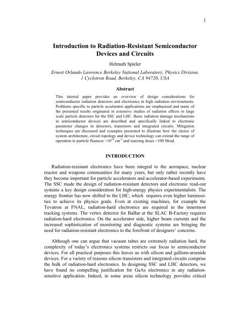
<strong>Introduction</strong> <strong>to</strong> Radiation-Resistant Semiconduc<strong>to</strong>r<br />
Devices <strong>and</strong> Circuits<br />
Helmuth Spieler<br />
Ernest Orl<strong>and</strong>o Lawrence Berkeley National Labora<strong>to</strong>ry, Physics Division,<br />
1 Cyclotron Road, Berkeley, CA 94720, USA<br />
Abstract<br />
This tu<strong>to</strong>rial paper provides an overview of design considerations for<br />
semiconduc<strong>to</strong>r <strong>radiation</strong> detec<strong>to</strong>rs <strong>and</strong> electronics in high <strong>radiation</strong> environments.<br />
Problems specific <strong>to</strong> particle accelera<strong>to</strong>r applications are emphasized <strong>and</strong> many of<br />
the presented results originated in extensive studies of <strong>radiation</strong> effects in large<br />
scale particle detec<strong>to</strong>rs for the SSC <strong>and</strong> LHC. Basic <strong>radiation</strong> damage mechanisms<br />
in semiconduc<strong>to</strong>r <strong>devices</strong> are described <strong>and</strong> specifically linked <strong>to</strong> electronic<br />
parameter changes in detec<strong>to</strong>rs, transis<strong>to</strong>rs <strong>and</strong> integrated <strong>circuits</strong>. Mitigation<br />
techniques are discussed <strong>and</strong> examples presented <strong>to</strong> illustrate how the choice of<br />
system architecture, circuit <strong>to</strong>pology <strong>and</strong> device technology can extend the range of<br />
operation <strong>to</strong> particle fluences >10 14 cm -2 <strong>and</strong> ionizing doses >100 Mrad.<br />
INTRODUCTION<br />
Radiation-<strong>resistant</strong> electronics have been integral <strong>to</strong> the aerospace, nuclear<br />
reac<strong>to</strong>r <strong>and</strong> weapons communities for many years, but only rather recently have<br />
they become important for particle accelera<strong>to</strong>rs <strong>and</strong> accelera<strong>to</strong>r-based experiments.<br />
The SSC made the design of <strong>radiation</strong>-<strong>resistant</strong> detec<strong>to</strong>rs <strong>and</strong> electronic read-out<br />
systems a key design consideration for high-energy physics experimentalists. The<br />
energy frontier has now shifted <strong>to</strong> the LHC, which requires even higher luminosities<br />
<strong>to</strong> achieve its physics goals. Even at existing machines, for example the<br />
Tevatron at FNAL, <strong>radiation</strong>-hard electronics are required in the innermost<br />
tracking systems. The vertex detec<strong>to</strong>r for BaBar at the SLAC B-Fac<strong>to</strong>ry requires<br />
<strong>radiation</strong>-hard electronics. On the accelera<strong>to</strong>r side, higher beam currents <strong>and</strong> the<br />
increased sophistication of moni<strong>to</strong>ring <strong>and</strong> diagnostic systems are bringing the<br />
need for <strong>radiation</strong>-<strong>resistant</strong> electronics <strong>to</strong> the forefront of designers’ concerns.<br />
Although one can argue that vacuum tubes are extremely <strong>radiation</strong> hard, the<br />
complexity of <strong>to</strong>day’s electronics systems restricts our focus <strong>to</strong> semiconduc<strong>to</strong>r<br />
<strong>devices</strong>. For all practical purposes this leaves us with silicon <strong>and</strong> gallium-arsenide<br />
<strong>devices</strong>. For a variety of reasons silicon transis<strong>to</strong>rs <strong>and</strong> integrated <strong>circuits</strong> comprise<br />
the bulk of <strong>radiation</strong>-hard electronics. In designing SSC <strong>and</strong> LHC detec<strong>to</strong>rs, we<br />
have found no compelling justification for GaAs electronics in any <strong>radiation</strong>sensitive<br />
application. Indeed, in some areas silicon technology provides critical<br />
1
performance advantages. For these reasons, despite the fascinating physics of<br />
compound semiconduc<strong>to</strong>rs, this tu<strong>to</strong>rial will emphasize silicon technology.<br />
The study of <strong>radiation</strong> effects in semiconduc<strong>to</strong>r electronics <strong>and</strong> the development<br />
of <strong>radiation</strong>-<strong>resistant</strong> integrated <strong>circuits</strong> have formed an active scientific<br />
community that has produced a wealth of data <strong>and</strong> conceptual underst<strong>and</strong>ing.<br />
Although access <strong>to</strong> some of these results <strong>and</strong> techniques is restricted, most of the<br />
data <strong>and</strong> papers are in the public domain <strong>and</strong> readily accessible, <strong>and</strong> they provide a<br />
valuable resource (see the Bibliography at the end of this paper). Although, much<br />
has been published on basic damage mechanisms <strong>and</strong> on device properties for<br />
specific applications, when attempting <strong>to</strong> apply this information <strong>to</strong> an area outside<br />
the traditional purview of the <strong>radiation</strong> effects community, key pieces of<br />
information needed <strong>to</strong> link basic damage mechanisms <strong>to</strong> usable design guidelines<br />
are often missing. This was very clear in the development of detec<strong>to</strong>rs for the SSC<br />
<strong>and</strong> LHC, where both the application of detec<strong>to</strong>rs with deep depletion regions <strong>and</strong><br />
novel circuit designs combining low-noise, high-speed <strong>and</strong> low power pushed<br />
developments in<strong>to</strong> uncharted terri<strong>to</strong>ry.<br />
This is a very complicated field <strong>and</strong> developing a general road map is not easy,<br />
but one can apply a few fundamental considerations <strong>to</strong> underst<strong>and</strong>ing the effects of<br />
<strong>radiation</strong> on device types in specific circuit <strong>to</strong>pologies <strong>and</strong> narrow the range of<br />
options that must be studied in detail. That is the thrust of this tu<strong>to</strong>rial. For lack of<br />
time, some treatments are sketchier than desirable <strong>and</strong> the reader should consult<br />
the references <strong>and</strong> the bibliography. This paper originated as a tu<strong>to</strong>rial talk at the<br />
1996 Beam Instrumentation Workshop at Argonne National Labora<strong>to</strong>ry in May,<br />
1996 <strong>and</strong> will be exp<strong>and</strong>ed <strong>and</strong> modified in response <strong>to</strong> criticisms <strong>and</strong> new<br />
developments. (1)<br />
RADIATION DAMAGE MECHANISMS<br />
Semiconduc<strong>to</strong>r <strong>devices</strong> are affected by two basic <strong>radiation</strong> damage<br />
mechanisms:<br />
• Displacement damage: Incident <strong>radiation</strong> displaces silicon a<strong>to</strong>ms from their<br />
lattice sites. The resulting defects alter the electronic characteristics of the<br />
crystal.<br />
• Ionization damage: Energy absorbed by electronic ionization in insulating<br />
layers, predominantly SiO2, liberates charge carriers, which diffuse or drift <strong>to</strong><br />
other locations where they are trapped, leading <strong>to</strong> unintended concentrations of<br />
charge <strong>and</strong>, as a consequence, parasitic fields.<br />
2
Both mechanisms are important in detec<strong>to</strong>rs, transis<strong>to</strong>rs <strong>and</strong> integrated <strong>circuits</strong>.<br />
Some <strong>devices</strong> are more sensitive <strong>to</strong> ionization effects, some are dominated by<br />
displacement damage. Hardly a system is immune <strong>to</strong> either one phenomena <strong>and</strong><br />
most are sensitive <strong>to</strong> both.<br />
Ionization effects depend primarily on the absorbed energy, independent of the<br />
type of <strong>radiation</strong>. At typical incident energies ionization is the dominant absorption<br />
mechanism, so that ionization damage can be measured in terms of energy absorption<br />
per unit volume, usually expressed in rad or gray (1 rad= 100 erg/g, 1 Gy= 1<br />
J/kg= 100 rad). Since the charge liberated by a given dose depends on the absorber<br />
material, the ionizing dose must be referred <strong>to</strong> a specific absorber, for example<br />
1 rad(Si), 1 rad(SiO2), 1 rad(GaAs), or in SI units 1 Gy(Si), etc.<br />
Displacement damage depends on the non-ionizing energy loss, i.e. energy <strong>and</strong><br />
momentum transfer <strong>to</strong> lattice a<strong>to</strong>ms, which depends on the mass <strong>and</strong> energy of the<br />
incident quanta. A simple measure as for ionizing <strong>radiation</strong> is not possible, so that<br />
displacement damage must be specified for a specific particle type <strong>and</strong> energy.<br />
In general, <strong>radiation</strong> effects must be measured for both damage mechanisms,<br />
although one may choose <strong>to</strong> combine both, for example by using pro<strong>to</strong>ns, if one<br />
has sufficient underst<strong>and</strong>ing <strong>to</strong> unravel the effects of the two mechanisms by electrical<br />
measurements. Even non-ionizing particles can deposit some ionization dose<br />
via recoils, but this contribution tends <strong>to</strong> be very small: 2⋅10 -13 rad per 1 MeV<br />
neutron/cm 2 , for example. (2)<br />
To set the scale, consider a tracking detec<strong>to</strong>r operating at the LHC with a<br />
luminosity of 10 34 cm -2 s -1 . In the innermost volume of a tracker the particle flux<br />
2 -2 -1<br />
cm s , increasing roughly twofold in the outer<br />
from collisions is n’≈ 2⋅10 9 /r⊥ layers due <strong>to</strong> interactions <strong>and</strong> loopers. At r =30 cm the particle fluence after one<br />
⊥<br />
year of operation (10 7 s) is about 2⋅10 13 cm -2 . A fluence of 3⋅10 13 cm -2 of minimum<br />
ionizing particles corresponds <strong>to</strong> an ionization dose of 1 Mrad, obtained after 1.5<br />
years of operation. Albedo neutrons from a calorimeter could add a yearly fluence<br />
of 10 12 <strong>to</strong> 10 13 cm -2 .<br />
Displacement Damage<br />
An incident particle or pho<strong>to</strong>n capable of imparting an energy of about 20 eV<br />
<strong>to</strong> a silicon a<strong>to</strong>m can dislodge it from its lattice site. Displacement damage creates<br />
defect clusters. For example, a 1 MeV neutron transfers about 60 <strong>to</strong> 70 keV <strong>to</strong> the<br />
Si recoil a<strong>to</strong>m, which in turn displaces roughly 1000 additional a<strong>to</strong>ms in a region of<br />
about 0.1 μm size. Displacement damage is proportional <strong>to</strong> non-ionizing energy<br />
loss (3), which is not proportional <strong>to</strong> the <strong>to</strong>tal energy absorbed, but depends on the<br />
particle type <strong>and</strong> energy. Non-ionizing energy loss for a variety of particles has<br />
3
een calculated over a large energy range. (4) Although not verified quantitatively,<br />
these curves can be used <strong>to</strong> estimate relative effects. X-rays do not cause direct<br />
displacement damage, since momentum conservation sets a threshold energy of<br />
250 keV for pho<strong>to</strong>ns. 60 Co γ rays cause displacement damage primarily through<br />
Comp<strong>to</strong>n electrons <strong>and</strong> are about three orders of magnitude less damaging per<br />
pho<strong>to</strong>n than a 1 MeV neutron. (5) Table 1 gives a rough comparison of displacement<br />
damage for several types of <strong>radiation</strong>.<br />
Particle pro<strong>to</strong>n pro<strong>to</strong>n neutron electron electron<br />
Energy 1 GeV 50 MeV 1 MeV 1 MeV 1 GeV<br />
Relative<br />
Damage<br />
1 2 2 0.01 0.1<br />
TABLE 1. Relative displacement damage for various particles <strong>and</strong> energies.<br />
Displacement damage manifests itself in three important ways:<br />
• formation of mid-gap states, which facilitate the transition of electrons from<br />
the valence <strong>to</strong> the conduction b<strong>and</strong>. In depletion regions this leads <strong>to</strong> a generation<br />
current, i.e. an increase in the current of reverse-biased pn-diodes. In<br />
forward biased junctions or non-depleted regions mid-gap states facilitate<br />
recombination, i.e. charge loss.<br />
• states close <strong>to</strong> the b<strong>and</strong> edges facilitate trapping, where charge is captured <strong>and</strong><br />
released after a certain time.<br />
• a change in doping characteristics (donor or accep<strong>to</strong>r density).<br />
The role of mid-gap states is illustrated in Fig. 1. Because interb<strong>and</strong> transitions<br />
in Si require momentum transfer (“indirect b<strong>and</strong>-gap”), direct transitions between<br />
the conduction <strong>and</strong> valence b<strong>and</strong>s are extremely improbable (unlike GaAs, for<br />
example). The introduction of intermediate states in the forbidden gap provides<br />
“stepping s<strong>to</strong>nes” for emission <strong>and</strong> capture processes. The individual steps,<br />
emission of holes or electrons <strong>and</strong> capture of electrons or holes, are illustrated in<br />
Fig. 1. As shown in Fig. 1a, the process of hole emission from a defect can also be<br />
viewed as promoting an electron from the valence b<strong>and</strong> <strong>to</strong> the defect level. In a<br />
second step (1b) this electron can proceed <strong>to</strong> the conduction b<strong>and</strong> <strong>and</strong> contribute<br />
<strong>to</strong> current flow, generation current. Conversely, a defect state can capture an<br />
4
electron from the conduction b<strong>and</strong> (1c), which in turn can capture a hole (1d). This<br />
“recombination” process reduces current flowing in the conduction b<strong>and</strong>.<br />
Since the transition probabilities are exponential functions of the energy differences,<br />
all processes that involve transitions between both b<strong>and</strong>s require mid-gap<br />
states <strong>to</strong> proceed at an appreciable rate. Given a distribution of states these processes<br />
will “seek out” the mid-gap states. Since the distribution of states is not necessarily<br />
symmetric, one cannot simply calculate recombination lifetimes from generation<br />
currents <strong>and</strong> vice versa (as is possible for a single mid-gap state, as<br />
assumed in textbooks). Whether generation or recombination dominates depends<br />
on the relative concentration of carriers <strong>and</strong> empty defect states. In a depletion<br />
region the conduction b<strong>and</strong> is underpopulated, so generation prevails. In a forward<br />
biased junction carriers flood the conduction b<strong>and</strong>, so recombination dominates.<br />
Fig. 1 also shows a third phenomenon; defect levels close <strong>to</strong> a b<strong>and</strong> edge will capture<br />
charge <strong>and</strong> release it after some time, a process called “trapping” (Fig. 1e).<br />
FIGURE 1. Emission <strong>and</strong> capture processes through intermediate states. The arrows<br />
show the direction of electron transitions.<br />
In a <strong>radiation</strong> detec<strong>to</strong>r or pho<strong>to</strong>diode system the increased reverse-bias current<br />
increases the electronic shot noise. The change in doping level affects the width of<br />
the depletion region (or the voltage required for full depletion). The decrease in<br />
carrier lifetime incurs a loss of signal as carriers recombine while traversing the<br />
depletion region. As will be shown later, the same phenomena occur in transis<strong>to</strong>rs,<br />
but are less pronounced, depending on device type <strong>and</strong> structure. Displacement<br />
damage effects will be discussed in more detail in the section on diodes.<br />
5
Ionization Damage<br />
As in the detec<strong>to</strong>r bulk, electron-hole pairs are created in the oxide. The electrons<br />
are quite mobile <strong>and</strong> move <strong>to</strong> the most positive electrode. Holes move by a rather<br />
complex <strong>and</strong> slow hopping mechanism, which promotes the probability of trapping<br />
in the oxide volume <strong>and</strong> an associated fixed positive charge. Holes that make it <strong>to</strong><br />
the oxide-silicon interface can be captured by interface traps. This is illustrated in<br />
Fig. 2, which shows a schematic cross-section of an n-channel MOSFET. A positive<br />
voltage applied <strong>to</strong> the gate electrode attracts electrons <strong>to</strong> the surface of the<br />
silicon beneath the gate. This “inversion” charge forms a conductive channel<br />
between the n+ doped source <strong>and</strong> drain electrodes. The substrate is biased negative<br />
relative <strong>to</strong> the MOSFET <strong>to</strong> form a depletion region for isolation. Holes freed<br />
by <strong>radiation</strong> accumulate at the oxide-silicon interface. The positive charge buildup<br />
at the silicon interface requires that the gate voltage be adjusted <strong>to</strong> more negative<br />
values <strong>to</strong> maintain the negative charge in the channel.<br />
Trapped oxide charge can also be mobile, so that the charge distribution generally<br />
depends on time, <strong>and</strong> more specifically, how the electric field in the oxide<br />
changes with time. The charge state of a trap depends on the local quasi Fermi<br />
level, so the concentration of trapped charge will vary with changes in the applied<br />
voltage <strong>and</strong> state-specific relaxation times. As charge states also anneal, ionization<br />
FIGURE 2. Schematic cross section of an n-channel MOSFET (left). A detail of the gate<br />
oxide shows the trapped holes at the oxide-silicon interface (right).<br />
6
effects depend not only on the dose, but also on the dose rate. Fig. 2 also shows a<br />
thick field oxide, which serves <strong>to</strong> control the silicon surface charge adjacent <strong>to</strong> the<br />
FET <strong>and</strong> prevent parasitic channels <strong>to</strong> adjacent <strong>devices</strong>. The same positive charge<br />
buildup as in the gate oxide also occurs here, indeed it can be exacerbated because<br />
the field oxide is quite thick. For more details, see ref. (6), currently the<br />
authoritative text on ionization effects.<br />
In summary, ionization effects are determined by<br />
• Interface trapped charge<br />
• Oxide trapped charge<br />
• The mobility of trapped charge<br />
• The time <strong>and</strong> voltage dependence of charge states<br />
Although the primary <strong>radiation</strong> damage depends only on the absorbed ionizing<br />
energy, the resulting effects of this dose depend on the rate of ir<strong>radiation</strong>, the<br />
applied voltages <strong>and</strong> their time variation, the temperature, <strong>and</strong> the time variation of<br />
the <strong>radiation</strong> itself. Ionization damage manifests itself most clearly in MOS field<br />
effect transis<strong>to</strong>rs, so it will be discussed in more detail in that section.<br />
EFFECTS ON DEVICE CHARACTERISTICS<br />
Radiation Damage in Diodes<br />
Diode structures are basic components of more complex <strong>devices</strong>, for example<br />
bipolar transis<strong>to</strong>rs, junction FETs <strong>and</strong> integrated <strong>circuits</strong>. Since the properties of<br />
diode depletion regions are determined primarily by bulk properties, measurements<br />
on diodes will serve <strong>to</strong> illustrate the effects of displacement damage. Reverse<br />
biased diodes with large depletion depths are used as <strong>radiation</strong> detec<strong>to</strong>rs <strong>and</strong><br />
pho<strong>to</strong>diodes. Because of their large depletion depths, typically hundreds of<br />
microns, detec<strong>to</strong>r diodes are very sensitive <strong>to</strong> bulk damage <strong>and</strong> extensive work by<br />
the SSC/LHC community has produced many insights in<strong>to</strong> bulk <strong>radiation</strong> effects.<br />
Affected are the detec<strong>to</strong>r leakage current, the doping characteristics, <strong>and</strong> charge<br />
collection.<br />
A theoretical analysis from first principles is quite complex, due <strong>to</strong> the many<br />
phenomena involved. Take doping changes as an example. Si interstitials are quite<br />
active <strong>and</strong> displace either P donors or B accep<strong>to</strong>rs from substitutional sites <strong>and</strong><br />
render them electrically inactive. These interstitial dopants <strong>to</strong>gether with oxygen,<br />
7
commonly present in the lattice as an impurity, react in very different ways with<br />
vacancies <strong>to</strong> form complexes with a variety of electronic characteristics (see ref.<br />
(7) <strong>and</strong> references therein). Fortui<strong>to</strong>usly, although a multitude of competing effects<br />
can be invoked in <strong>to</strong> predict <strong>and</strong> interpret experimental results, the data can be<br />
described by rather simple parametrizations.<br />
The increase in reverse bias current (leakage current) is linked <strong>to</strong> the creation<br />
of mid-gap states. Experimental data are consistent with a uniform distribution of<br />
active defects in the detec<strong>to</strong>r volume. The bias current after ir<strong>radiation</strong><br />
Idet = I0 + α ⋅Φ ⋅ Ad<br />
(1)<br />
where I0 is the bias current before ir<strong>radiation</strong>, α is a damage coefficient dependent<br />
on particle type <strong>and</strong> fluence, Φ is the particle fluence, <strong>and</strong> the product of detec<strong>to</strong>r<br />
area <strong>and</strong> thickness Ad is the detec<strong>to</strong>r volume. For 650 MeV pro<strong>to</strong>ns α≈<br />
3⋅10 -17 A/cm (8,9) <strong>and</strong> for 1 MeV neutrons (characteristic of the albedo emanating<br />
from a calorimeter) α≈ 2⋅10 -17 A/cm. (9) The parametrization used in Eq. 1 is quite<br />
general, as it merely assumes a spatially uniform formation of electrically active<br />
defects in the detec<strong>to</strong>r volume, without depending on the details of energy levels<br />
or states.<br />
The coefficients given above apply <strong>to</strong> room temperature operation. The reverse<br />
bias current of silicon detec<strong>to</strong>rs depends strongly on temperature<br />
2 − E / 2k<br />
T<br />
IR ( T ) ∝ T e B<br />
if the generation current dominates (10), as is the case for substantial <strong>radiation</strong><br />
damage. The effective activation energy E= 1.2 eV for <strong>radiation</strong> damaged samples<br />
(8)(11)(12), whereas unirradiated samples usually exhibit E= 1.15 eV. The ratio of<br />
currents at two temperatures T1 <strong>and</strong> T2 is<br />
2<br />
IR<br />
( T2<br />
) ⎛ T ⎞ ⎡ ⎛ − ⎞⎤<br />
= ⎜ 2 E T<br />
⎟ ⎢−<br />
⎜ 1 T<br />
exp<br />
2 ⎟⎥<br />
(3)<br />
IR<br />
( T1)<br />
⎝ T1<br />
⎠ ⎣ 2kB<br />
⎝ T1T2<br />
⎠⎦<br />
After ir<strong>radiation</strong> the leakage current initially decreases with time. Pronounced<br />
short term <strong>and</strong> long term annealing components are observed <strong>and</strong> precise fits <strong>to</strong> the<br />
annealing curve require a sum of exponentials. (9) Experimentally, decreases by<br />
fac<strong>to</strong>rs of 2 <strong>to</strong> 3 have been observed with no further improvement after 5 months<br />
or so. (8,5) In practice, the variation of leakage current with temperature is very<br />
reproducible from device <strong>to</strong> device, even after substantial doping changes due <strong>to</strong><br />
<strong>radiation</strong> damage. The leakage current can be used for dosimetry <strong>and</strong> diodes are<br />
offered commercially specifically for this purpose.<br />
8<br />
(2)
The effect of displacement damage on doping characteristics has been<br />
investigated in the course of detec<strong>to</strong>r studies for the SSC <strong>and</strong> LHC <strong>and</strong> is still the<br />
subject of ongoing study. Measurements on a variety of strip detec<strong>to</strong>rs <strong>and</strong> pho<strong>to</strong>diodes<br />
by groups in the U.S., Japan <strong>and</strong> Europe have shown that the effective<br />
doping of n type silicon initially decreases, becomes intrinsic (i.e. very little space<br />
charge) <strong>and</strong> then turns p-like, with the space charge increasing with fluence. This<br />
phenomenon is consistent with the notion that accep<strong>to</strong>r sites are formed by the<br />
ir<strong>radiation</strong>, although this does not mean that mobile holes are created. (13)<br />
Initially, the effective doping level Nd -Na decreases as new accep<strong>to</strong>r states<br />
neutralize original donor states. At some fluence the two balance, creating<br />
“intrinsic” material, <strong>and</strong> beyond this fluence the accep<strong>to</strong>r states dominate. In<br />
addition, there is evidence for a concurrent process of donor removal. (14,15)<br />
Since the probability of donor removal is proportional <strong>to</strong> the initial donor<br />
concentration Nd0, whereas the formation of defects leading <strong>to</strong> accep<strong>to</strong>r states is<br />
proportional <strong>to</strong> fluence, the effective space charge density Neff of n type starting<br />
material after exposure <strong>to</strong> a particle fluence Φ is described by (16)<br />
− cΦ<br />
− t / τ ( T )<br />
Neff ( Φ ) = − Nd 0e<br />
+ gcΦ + gsΦ ⋅ e + NY ( Φ , t, T )<br />
where a negative or positive sign of Neff denotes whether the effective space charge<br />
is n- or p-like. The first term describes the removal of donors <strong>and</strong> the second the<br />
creation of accep<strong>to</strong>rs. c <strong>and</strong> gc are constants for a given particle type <strong>and</strong> energy<br />
that describe the stable component of <strong>radiation</strong> damage. The third <strong>and</strong> fourth terms<br />
describe the time <strong>and</strong> temperature dependent changes in the effective doping concentration<br />
<strong>and</strong> will be discussed later. For high energy pro<strong>to</strong>ns the average from<br />
many measurements is c= (0.96±0.19)⋅10 -13 cm 2 <strong>and</strong> gc = (1.15±0.09)⋅10 -2 cm -1 .<br />
Type inversion from n <strong>to</strong> p type silicon occurs at a fluence of about 10 13 cm -2 . Data<br />
for 1 MeV equivalent neutrons yield c= (2.29±0.63)⋅10 -13 cm 2 <strong>and</strong><br />
gc = (1.77±0.07)⋅10 -2 cm -1 . (9)<br />
After a pro<strong>to</strong>n fluence Φ= 10 14 cm -2 the accep<strong>to</strong>r concentration before annealing<br />
is 10 12 cm -3 , which requires a bias voltage of 165V for full depletion of a 300<br />
μm thick detec<strong>to</strong>r. At first glance, it would seem that beginning with a higher<br />
n doping level Nd0 (lower resistivity) would increase overall detec<strong>to</strong>r lifetime.<br />
Although the inversion fluence increases with larger values of Nd0 , the difference in<br />
doping concentration is negligible at larger fluences since the exponential term<br />
quickly becomes insignificant. (15) For example, as shown in Fig. 3 materials with<br />
initial doping densities of 10 12 cm -3 <strong>and</strong> 10 13 cm -3 lie within 15% at Φ= 5⋅10 13 cm -2 .<br />
Very high resistivity silicon (ρ >10 kΩcm or Nd < 4⋅10 11 cm -3 ) is often highly<br />
compensated, Neff=Nd -Na with Nd ~Na>>Neff , so that minute changes <strong>to</strong> either<br />
donors or accep<strong>to</strong>rs can alter the net doping concentration significantly, <strong>and</strong> the<br />
9<br />
(4)
Effective Doping Concentration [cm -3 ]<br />
10 14<br />
10 13<br />
10 12<br />
10 11<br />
10 10<br />
10 9<br />
10 8<br />
10 11<br />
N d0 = 10 13 cm -3<br />
N d0 = 10 12 cm -3<br />
10 12<br />
above equations must be modified accordingly. Moderate resistivity n type material<br />
(ρ = 1 <strong>to</strong> 5 kΩcm) used in large area tracking detec<strong>to</strong>rs is usually dominated by<br />
donors.<br />
Annealing of ionized accep<strong>to</strong>r states<br />
After defect states are formed by ir<strong>radiation</strong>, their electronic activity changes<br />
with time. A multitude of processes contribute, some leading <strong>to</strong> beneficial<br />
annealing, i.e. a reduction in accep<strong>to</strong>r-like states, <strong>and</strong> some increasing the accep<strong>to</strong>r<br />
concentration. The third term in Eq. 4 describes the beneficial annealing (17),<br />
where gs= 1.93⋅10 -2 cm -1 <strong>and</strong> τ (T)= (6⋅10 6 )⋅exp[-0.175(T-273.2)] s (<strong>to</strong> set the<br />
scale, τ(0°C)= 70 d). The fourth term in Eq. 4<br />
⎡<br />
NY ( Φ , t1/2 , T ) = gYΦ<br />
⋅⎢1− ⎣<br />
10 13<br />
Fluence [cm -2 ]<br />
10 14<br />
FIGURE 3. Calculated effective doping concentration vs. high-energy pro<strong>to</strong>n<br />
fluence for silicon with initial donor concentrations N d0 of 10 12 <strong>and</strong> 10 13 cm -3 .<br />
1 ⎤<br />
1+<br />
gYΦ ⋅ k( T ) ⋅<br />
⎥<br />
t ⎦<br />
10 15<br />
where for 1 MeV neutrons gY= (4.6±0.3)⋅10 -2 cm -1 <strong>and</strong> for 1 GeV pro<strong>to</strong>ns values<br />
of gY= (4.97±0.23)⋅10 -2 cm -1 (16) <strong>and</strong> (5.8±0.3)⋅10 -2 cm -1 (9) have been found. The<br />
temperature dependent evolution is determined by<br />
10<br />
(5)<br />
−<br />
k T k e<br />
Ea / kBT ( ) = 0 (6)
Typical parameter sets are k0 = (0.85+25-0.82) cm 3 /s <strong>and</strong> Ea= 1.16±0.08 eV (16),<br />
<strong>and</strong> k0 = (520+1590-392) cm 3 /s <strong>and</strong> Ea= 1.31±0.04 eV (9).<br />
Anti-annealing is a concern because of its effect on detec<strong>to</strong>r depletion voltage,<br />
i.e. the voltage required <strong>to</strong> collect mobile charge from the complete thickness of<br />
the silicon detec<strong>to</strong>r. Since this voltage increases with space-charge concentration,<br />
antiannealing can easily exceed the safe operating range, especially at high<br />
fluences. The relative effect of anti-annealing increases strongly with fluence <strong>and</strong><br />
temperature, as illustrated in Table 2, which shows the relative increase in doping<br />
<strong>and</strong> required operating voltage. Clearly, low temperature operation is beneficial.<br />
Nevertheless, even a low temperature system will require maintenance at room<br />
temperature <strong>and</strong> warm up periods must be controlled very carefully. (9,16)<br />
Fluence [cm -2 ]<br />
10 13<br />
10 14<br />
Na (t=100h)/Na(t=0) = V (t=100h)/V (t=0)<br />
0 °C 20 °C 40 °C<br />
1.00 1.02 1.39<br />
1.01 1.21 4.71<br />
TABLE 2. Relative antiannealing after 100 h vs. fluence <strong>and</strong> temperature<br />
Data on charge collection efficiency are still rather sketchy. The primary<br />
mechanism is expected <strong>to</strong> be trapping of signal charge at defect sites, i.e. a<br />
decrease in carrier lifetime τ. Since the loss in signal charge is proportional <strong>to</strong><br />
exp(-tc /τ ), reducing the collection time mitigates the effect. Since either the<br />
operating voltage is increased or depletion widths are reduced at damage levels<br />
where charge trapping is appreciable, fields tend <strong>to</strong> be higher <strong>and</strong> collection times<br />
decrease au<strong>to</strong>matically with <strong>radiation</strong> damage, provided the detec<strong>to</strong>r can sustain<br />
the higher fields.<br />
Typical measurements have determined the signal charge vs. bias voltage <strong>and</strong><br />
have taken the plateau value (or the maximum signal charge just below breakdown).<br />
Lemeilleur et al. (18) find ΔQ/Q0 = γΦ, where γ = (0.024±0.004)⋅10 -13 cm 2<br />
for 1 MeV equivalent neutrons. Fretwurst et al. (19) find similar results, with a<br />
dependence 1/τ = γΦ, where for holes γp= 2.7⋅10 -7 cm 2 s <strong>and</strong> for electrons<br />
γe= 1.2⋅10 -6 cm 2 s for Φ>10 13 cm -2 of 1 MeV equivalent neutrons. For a fluence<br />
Φ= 5⋅10 13 cm -2 s -1 , a 400 μm thick detec<strong>to</strong>r with a depletion voltage of 130V<br />
operated at a bias voltage of 200V would show a decrease in signal charge of<br />
12%. Ohsugi et al. (20) have demonstrated the operation of strip detec<strong>to</strong>rs <strong>to</strong><br />
neutron fluences beyond 10 14 cm -2 , with signal losses of about 10%. Similar results<br />
11
have been obtained on fully irradiated strip detec<strong>to</strong>rs read out by LHC compatible<br />
electronics. (21)<br />
The basic detec<strong>to</strong>r is insensitive <strong>to</strong> ionization effects. In the bulk, ionizing<br />
<strong>radiation</strong> creates electrons <strong>and</strong> holes that are swept from the sensitive volume;<br />
charge can flow freely through the external circuitry <strong>to</strong> res<strong>to</strong>re equilibrium. The<br />
problem lies in the peripheral structures, the oxide layers that are essential <strong>to</strong> controlling<br />
leakage paths at the edge of the diode <strong>and</strong> <strong>to</strong> preserving inter-electrode<br />
isolation in segmented detec<strong>to</strong>rs.<br />
The positive space charge due <strong>to</strong> hole trapping in the oxide <strong>and</strong> at the interface<br />
(see Fig. 2) attracts electrons in the silicon bulk <strong>to</strong> the interface. These accumulation<br />
layers can exhibit high local electron densities <strong>and</strong> form conducting channels,<br />
for example between the detec<strong>to</strong>r electrodes. This is especially critical at the<br />
“ohmic” electrodes in double-sided detec<strong>to</strong>rs, where the absence of pn junctions<br />
makes operation rely on full depletion of the silicon surface (even without <strong>radiation</strong>,<br />
the silicon surface tends <strong>to</strong> be n-type, so the ohmic side of n type detec<strong>to</strong>rs is<br />
inherently more difficult <strong>to</strong> control). (22,23)<br />
Some detec<strong>to</strong>rs include integrated coupling capaci<strong>to</strong>rs <strong>and</strong> biasing networks.<br />
Biasing structures such as punch-through resis<strong>to</strong>rs <strong>and</strong> MOSFET structures are<br />
subject <strong>to</strong> ionization damage. Although these <strong>devices</strong> can remain functional, substantial<br />
changes in voltage drop have been reported for punch-through <strong>and</strong> accumulation<br />
layer <strong>devices</strong>, whereas measurements on polysilicon resis<strong>to</strong>rs irradiated <strong>to</strong><br />
4 Mrad (65 MeV p) show no effect. (24)<br />
Radiation Damage in Transis<strong>to</strong>rs <strong>and</strong> Integrated Circuits<br />
In principle, the same phenomena discussed for detec<strong>to</strong>rs also occur in transis<strong>to</strong>rs,<br />
except that the geometries of transis<strong>to</strong>rs are much smaller (depletion widths<br />
10 15 cm -3 ).<br />
Bipolar Transis<strong>to</strong>rs<br />
The most important damage mechanism in bipolar transis<strong>to</strong>rs is the degradation<br />
of DC current gain at low currents. The damage mechanism is the same that causes<br />
increased leakage current in detec<strong>to</strong>rs, formation of mid-gap states by displacement<br />
damage. The difference is that the base-emitter junction is forward biased, so<br />
the high carrier concentration in the conduction b<strong>and</strong> tips the balance from generation<br />
<strong>to</strong> recombination (see Fig. 1). The fractional carrier loss depends on the<br />
relative concentrations of injected carriers <strong>and</strong> defects. Consequently, the<br />
reduction of DC current gain due <strong>to</strong> <strong>radiation</strong> damage depends on current density.<br />
For a given collec<strong>to</strong>r current a small device will suffer less degradation in DC<br />
current gain than a large one.<br />
12
Since the probability of recombination depends on the transit time through the<br />
junction region, reduced base width will also improve the <strong>radiation</strong> resistance.<br />
Base width is strongly linked with device speed, so that the reduction in DC<br />
current gain βDC scales inversely with a transis<strong>to</strong>r’s unity gain frequency fT . (25)<br />
1 1 Φ<br />
= +<br />
βDC<br />
β0<br />
fT<br />
Since IC technology is driven primarily by device speed, mainstream market<br />
forces will indirectly improve the <strong>radiation</strong> resistance of bipolar transis<strong>to</strong>r processes.<br />
Mid-gap states also limit the low current performance before ir<strong>radiation</strong>.<br />
Over the past decade, evolutionary improvements in contamination control <strong>and</strong><br />
process technology have also yielded substantially better low-current performance.<br />
Measurements on bipolar transis<strong>to</strong>rs from several vendors have shown that processes<br />
not specifically designed for <strong>radiation</strong> resistance are indeed quite usable in<br />
severe <strong>radiation</strong> environments, even at low currents. (26,27,28).<br />
Changes in doping levels have little effect in bipolar transis<strong>to</strong>rs. Typical doping<br />
levels in the base <strong>and</strong> emitter are NB= 10 18 <strong>and</strong> NE= 10 20 cm -3 . In the collec<strong>to</strong>r<br />
depletion region doping levels are smaller, typically 10 16 , rising <strong>to</strong> 10 18 or 10 19 at<br />
the collec<strong>to</strong>r contact. At these levels the change in doping level due <strong>to</strong> displacement<br />
damage (ΔNA ≈ 10 12 cm -3 at Φ= 10 14 cm -2 ) is negligible, although local device<br />
temperatures may be high enough that anti-annealing leads <strong>to</strong> noticeable effects.<br />
DC CURRENT GAIN<br />
100<br />
90<br />
80<br />
70<br />
60<br />
50<br />
40<br />
30<br />
20<br />
10<br />
0<br />
50<br />
NPN PNP<br />
PRE-RAD<br />
POST RAD<br />
10 -5 10 -4 10 -3 10 -2 10 -1 10 0 10 1 10 2 10 3<br />
EMITTER CURRENT DENSITY [μA/(μm) 2 ]<br />
DC CURRENT GAIN<br />
40<br />
30<br />
20<br />
10<br />
0<br />
PRE-RAD<br />
POST-RAD<br />
13<br />
(7)<br />
10 -5 10 -4 10 -3 10 -2 10 -1 10 0 10 1 10 2 10 3<br />
EMITTER CURRENT DENSITY [μA/(μm) 2 ]<br />
FIGURE 4. DC current gain of npn <strong>and</strong> pnp transis<strong>to</strong>rs before <strong>and</strong> after ir<strong>radiation</strong> <strong>to</strong> a<br />
fluence of 1.2⋅10 14 cm -2 (800 MeV pro<strong>to</strong>ns).
OUTPUT NOISE VOLTAGE DENSITY [μV/√Hz]<br />
0.15<br />
0.10<br />
0.05<br />
0.00<br />
post-rad<br />
pre-rad<br />
1E+5 1E+6 1E+7 1E+8<br />
FREQUENCY [Hz]<br />
FIGURE 5. Noise of a bipolar transis<strong>to</strong>r preamplifier before <strong>and</strong> after ir<strong>radiation</strong> <strong>to</strong> a<br />
fluence of 1.2⋅10 14 cm -2 (800 MeV pro<strong>to</strong>ns).<br />
Figure 4 shows measured DC current gain for npn <strong>and</strong> pnp bipolar transis<strong>to</strong>rs<br />
irradiated <strong>to</strong> a fluence of 1.2⋅10 14 cm -2 (800 MeV pro<strong>to</strong>ns). (26) These <strong>devices</strong>,<br />
fabricated in AT&T’s CBIC-V2 high-density complementary npn-pnp IC process,<br />
exhibit fT = 10 GHz for the npn <strong>and</strong> 4.5 GHz for the pnp transis<strong>to</strong>rs. In the CAFE<br />
chip designed for the ATLAS silicon tracker (29) the npn input device is operated<br />
at a current density of about 2 μA/(μm) 2 , where the post-rad current gain<br />
decreases <strong>to</strong> about 60% of its initial value. Although a smaller transis<strong>to</strong>r would<br />
deteriorate less, the thermal noise contribution of the parasitic base resistance<br />
would be excessive, so a compromise is necessary. No measurable changes in<br />
transconductance were measured, as expected. The output resistance of these<br />
<strong>devices</strong> decreased by
Junction Field Effect Transis<strong>to</strong>rs (JFETs)<br />
JFETs (either silicon or GaAs) can be quite insensitive <strong>to</strong> both ionization <strong>and</strong><br />
displacement effects. In these <strong>devices</strong> a conducting channel from the source <strong>to</strong> the<br />
drain is formed by appropriate doping, typically n type. The gate electrode is<br />
doped p type so that applying a reverse bias voltage relative <strong>to</strong> the channel will<br />
form a depletion region that changes the cross section of the conducting channel.<br />
(31) At low values of gate <strong>and</strong> drain voltages the channel is contiguous <strong>and</strong><br />
resistive. At higher voltage levels the channel becomes fully depleted near the<br />
drain, but the current flow is still determined by the conducting channel near the<br />
source. Since the gate voltage now controls both the geometry <strong>and</strong> potential<br />
distribution, voltage-current characteristics become more complex <strong>and</strong> the device<br />
acts much like a controlled current source, i.e. it exhibits a high output resistance.<br />
With respect <strong>to</strong> <strong>radiation</strong> effects, the important fact is that device characteristics<br />
are determined essentially by the geometry <strong>and</strong> doping level of the channel.<br />
Typical doping levels are 10 15 <strong>to</strong> 10 18 cm -3 , so the effect of <strong>radiation</strong>-induced<br />
accep<strong>to</strong>r states is small. Silicon JFETs exhibit very good <strong>radiation</strong> resistance.<br />
Measurements on both st<strong>and</strong>ard commercial <strong>devices</strong> <strong>and</strong> cus<strong>to</strong>m designed integrated<br />
<strong>circuits</strong> have shown minimal changes in gain at fluences >10 14 neutrons/cm 2<br />
<strong>and</strong> ionization doses up <strong>to</strong> 100 Mrad. (32,33,34). Low frequency noise<br />
(f < 100 kHz) may increase by an order of magnitude, but at high frequencies very<br />
little change in noise is observed. Measurements of Si JFETs at 90K also exhibit<br />
excellent <strong>radiation</strong> characteristics. (33)<br />
In some applications, analog s<strong>to</strong>rage circuitry for example, gate leakage<br />
current is important. Generation current in the gate depletion region due <strong>to</strong><br />
displacement damage can affect the gate current strongly. Measurements on<br />
commercial JFETs irradiated by high-energy electrons <strong>to</strong> 100 Mrad (Φ≈ 10 15 cm -2 )<br />
show the gate reverse current increasing 100 fold from an initial value of 70 pA.<br />
(35) Here one should choose the smallest geometry device commensurate with<br />
other requirements.<br />
At this point it is worth noting that the superior <strong>radiation</strong> resistance claimed for<br />
GaAs ICs has more <strong>to</strong> do with the use of JFETs or MESFETs (a Schottky barrier<br />
JFET) than the properties of the semiconduc<strong>to</strong>r. These <strong>devices</strong> are more <strong>radiation</strong><br />
<strong>resistant</strong> than silicon MOSFETs (discussed below), but suffer from a much lower<br />
circuit density.<br />
15
Metal-Oxide Silicon Field Effect Transis<strong>to</strong>rs (MOSFETs)<br />
Within the FET family, MOSFETs present the most pronounced ionization<br />
effects, as the key <strong>to</strong> their operation lies in the oxide that couples the gate <strong>to</strong> the<br />
channel. As described above <strong>and</strong> illustrated in Fig. 2, positive charge buildup due<br />
<strong>to</strong> hole trapping in the oxide <strong>and</strong> at the interface shifts the gate voltage required for<br />
a given operating point <strong>to</strong> more negative values. This shift affects the operating<br />
points in analog circuitry <strong>and</strong> switching times in digital circuitry. Reducing the<br />
thickness of the gate oxide <strong>to</strong>x greatly improves the <strong>radiation</strong> resistance; gate<br />
voltage shifts scaling with <strong>to</strong>x 2 <strong>to</strong> <strong>to</strong>x 3 for a given dose have been observed. (6)<br />
Thinner gate oxides are required for small channel lengths, so higher density processes<br />
tend <strong>to</strong> improve the <strong>radiation</strong> resistance even without special hardening<br />
techniques. The gate voltage shift is typically expressed in terms of threshold<br />
voltage VT, which roughly marks the onset of appreciable current flow.<br />
Typical threshold shifts for a 1.2 μm <strong>radiation</strong>-hardened CMOS IC process<br />
with a 20 nm thick gate oxide are shown in Fig. 6. (36) After exposure <strong>to</strong><br />
5 Mrad(Si) of 60 Co ir<strong>radiation</strong>, NMOS thresholds shift by 200 mV <strong>and</strong> PMOS<br />
levels change by 150 mV. For both NMOS <strong>and</strong> PMOS <strong>devices</strong> the threshold<br />
voltage shifts <strong>to</strong> more negative values as expected from positive charge buildup in<br />
the oxide. The slight upturn above 2 Mrad in the NMOS curve is typical <strong>and</strong><br />
reflects the buildup of interface states. (6) About 70% of the threshold shifts occur<br />
during the first 250 krad, also a typical phenomenon. Measurements <strong>to</strong> 125 Mrad<br />
on a similar process show a <strong>to</strong>tal threshold shift of 400 mV for NMOS <strong>and</strong> 100<br />
mV for PMOS with little increase beyond 10 Mrad. (37)<br />
THRESHOLD [V]<br />
0.8<br />
0.7<br />
0.6<br />
0 1 2 3 4 5<br />
DOSE [Mrad]<br />
-0.8<br />
NMOS PMOS<br />
THRESHOLD [V]<br />
-0.9<br />
-1.0<br />
16<br />
0 1 2 3 4 5<br />
DOSE [Mrad]<br />
FIGURE 6. Threshold voltage shifts for <strong>radiation</strong>-hardened NMOS <strong>and</strong> PMOS<br />
transis<strong>to</strong>rs vs. 60 Co <strong>radiation</strong> dose.
g m / I d<br />
g m / I d<br />
30<br />
20<br />
10<br />
0<br />
20<br />
10<br />
0<br />
10 -4 10 -3 10 -2 10 -1 10 0<br />
I d / W [A/m]<br />
NMOS: 0 Mrad<br />
NMOS: 5 Mrad<br />
10 1<br />
10 2<br />
Figure 7 shows the normalized transconductance gm/Id vs. Id/W before <strong>and</strong> after<br />
ir<strong>radiation</strong>. (36) For the selected channel length this representation allows direct<br />
scaling <strong>to</strong> any device width at a given current density. For example, <strong>to</strong> operate a<br />
1.2 μm NMOS transis<strong>to</strong>r in moderate inversion one might choose a normalized<br />
drain current Id /W= 0.3 A/m, yielding Id= 0.3 mA for a 1 mm wide transis<strong>to</strong>r. The<br />
normalized transconductance gm /Id= 15.4 V -1 or gm= 4.6 mS. After exposure <strong>to</strong><br />
5 Mrad gm /Id= 11.8 V -1 or gm= 3.5 mS. Typically, the NMOS <strong>devices</strong> suffer a 20<br />
<strong>to</strong> 30% degradation, whereas the PMOS <strong>devices</strong> are quite insensitive <strong>to</strong> <strong>radiation</strong>,<br />
with only a few percent decrease in transconductance at 5 Mrad. About half of the<br />
observed change at 5 Mrad occurred before attaining a dose of 1 Mrad.<br />
Extensive noise measurements have been performed at the University of<br />
Pennsylvania (38) <strong>and</strong> by a UCSC/LBNL group. (36) In the latter, spectral noise<br />
density was measured over a frequency range of 10 kHz <strong>to</strong> 10 MHz before <strong>and</strong><br />
g m / I d<br />
g m / I d<br />
40<br />
30<br />
20<br />
10<br />
0<br />
30<br />
20<br />
10<br />
0<br />
L= 1.2<br />
L= 2.2<br />
L= 3.2<br />
10 -4 10 -3<br />
10 -2 10 -1<br />
I d /W [A/m]<br />
PMOS: 0 Mrad<br />
PMOS: 5 Mrad<br />
FIGURE 7. Normalized transconductance g m / I d vs. drain current I d /W for NMOS <strong>and</strong><br />
PMOS transis<strong>to</strong>rs with channel lengths of 1.2, 2.2 <strong>and</strong> 3.2 μm before <strong>and</strong> after 60 Co<br />
ir<strong>radiation</strong> <strong>to</strong> 5 Mrad (Si).<br />
10 0<br />
10 1<br />
17<br />
10 2
Type NMOS PMOS NMOS PMOS NMOS PMOS NMOS PMOS<br />
Width 75 75 1332 1332 888 888 1332 1332<br />
Length 1.2 1.2 1.2 1.2 2.2 2.2 3.2 3.2<br />
Id /W= 0.03<br />
0 Mrad 0.81 0.61 0.64 0.59 0.66 0.50<br />
5 Mrad 2.17 0.84 1.00 0.58 1.50 0.69<br />
Id /W= 0.1<br />
0 Mrad 1.10 0.70 1.20 1.10 0.80 0.80 0.80 0.60<br />
5 Mrad 3.80 1.10 3.40 1.60 1.30 0.90 1.70 0.70<br />
Id /W= 0.3<br />
0 Mrad 1.60 1.30 2.00 1.70 1.10 1.00 1.10 0.77<br />
5 Mrad 5.00 2.90 4.80 2.70 1.60 1.40 1.20 0.81<br />
TABLE 3. Noise coefficients γ n=v n<br />
2 ⋅ gm /4kT for NMOS <strong>and</strong> PMOS transis<strong>to</strong>rs of various<br />
widths <strong>and</strong> lengths, operated at current densities I d /W= 0.03, 0.10 <strong>and</strong> 0.3 A/m, before<br />
<strong>and</strong> after 60 Co ir<strong>radiation</strong> <strong>to</strong> 5 Mrad(Si). Widths <strong>and</strong> lengths are given in μm.<br />
after 60 Co ir<strong>radiation</strong> <strong>to</strong> a dose of 5 Mrad(Si). The noise was measured at three<br />
representative drain current densities Id/W. Again, these data can be scaled <strong>to</strong> any<br />
device width, where the noise scales with W -1/2 . The difference between the<br />
NMOS <strong>and</strong> PMOS results is striking. The NMOS <strong>devices</strong> show a much greater<br />
degradation <strong>and</strong> the PMOS <strong>devices</strong> also exhibit substantially less low-frequency<br />
noise. The low-frequency noise spectral density of the NMOS <strong>devices</strong> can be<br />
described by vn 2 = Af /q + B, where q ranges from 0.8 <strong>to</strong> 1.0 <strong>and</strong> is constant for all<br />
currents for the same geometry. The changes in q after a dose of 5 Mrad are of<br />
order 0.1. The noise coefficient Af is about 1.0 <strong>to</strong> 1.5⋅10 -30 V 2 pre-rad <strong>and</strong> 5 <strong>to</strong><br />
10⋅10 -30 V 2 post-rad. Before ir<strong>radiation</strong>, Af scales well with inverse gate area, but<br />
no clear pattern is observed after ir<strong>radiation</strong>. The low frequency noise behavior of<br />
the PMOS <strong>devices</strong> is more complex <strong>and</strong> cannot be parameterized in this simple<br />
manner, but the <strong>devices</strong> exhibit substantially better noise than the NMOS<br />
transis<strong>to</strong>rs.<br />
White noise was evaluated at high frequencies <strong>and</strong> is characterized by the noise<br />
coefficient γn= vn 2 ⋅ gm /4kT <strong>to</strong> assess the inherent noise properties independent of<br />
transconductance. Results for various device geometries <strong>and</strong> current densities are<br />
shown in Table 3. For these measurements the substrate was biased at the source<br />
potential.<br />
18
Again, we see substantially less post-<strong>radiation</strong> degradation in the PMOS<br />
<strong>devices</strong>. One can also observe the higher intrinsic noise of NMOS short channel<br />
<strong>devices</strong>. Although the observed degradation is quite small in some cases, typically<br />
it is quite substantial <strong>and</strong> would need <strong>to</strong> be compensated for by a considerably<br />
higher operating current. Seller et al. have exposed low-noise preamplifiers fabricated<br />
in a rad-hard 1.2 μm bulk CMOS process <strong>to</strong> a dose of 100 Mrad <strong>and</strong> measured<br />
noise <strong>and</strong> gain. (37) Gain decreased by no more than 7%, but the increase in<br />
equivalent input noise at high frequencies ranged from 20 <strong>to</strong> 75%. This process is<br />
only specified <strong>to</strong> 5 Mrad, so these results indicate that <strong>circuits</strong> are still quite usable<br />
at much higher doses, if one can accommodate the increase in noise.<br />
Due <strong>to</strong> the presence of mobile trapped charge, threshold behavior can become<br />
quite difficult <strong>to</strong> predict when the gate voltage changes appreciably with varying<br />
duty cycles, as in logic circuitry. Detec<strong>to</strong>rs <strong>and</strong> analog circuitry are simpler by<br />
comparison, since the voltage levels are either static or change with a fixed period,<br />
as in analog pipelines, for example. In general, when performing ionization damage<br />
tests <strong>devices</strong> must be operated at typical operating voltages <strong>and</strong> digital circuitry<br />
must be clocked at frequencies <strong>and</strong> patterns approximating typical operation.<br />
Generally speaking, both bulk <strong>and</strong> SOI (silicon on insula<strong>to</strong>r) CMOS are subject<br />
<strong>to</strong> the effects described above. SOI is often cited as a specifically <strong>radiation</strong>-hard<br />
technology because of its resistance <strong>to</strong> transient <strong>radiation</strong> effects, primarily latchup<br />
due <strong>to</strong> pho<strong>to</strong>currents developed at high intensity bursts of <strong>radiation</strong><br />
(>10 6 -10 7 rad/s) typical of nuclear de<strong>to</strong>nations. Although SOI can provide<br />
superior device speed because of reduced stray capacitance, this technology is not<br />
inherently more <strong>resistant</strong> <strong>to</strong> <strong>radiation</strong> in our applications. If anything, the additional<br />
oxide interfaces tend <strong>to</strong> complicate matters <strong>and</strong> at this time most <strong>radiation</strong>-<strong>resistant</strong><br />
CMOS processes are on bulk silicon.<br />
Radiation Effects in Integrated Circuit Structures<br />
The preceding discussion has emphasized the properties of individual <strong>devices</strong>.<br />
In integrated <strong>circuits</strong> many <strong>devices</strong> are placed close <strong>to</strong>gether. As mentioned above,<br />
the silicon surface is naturally n-type, so isolation structures are required <strong>to</strong><br />
preclude unwanted cross-coupling between <strong>devices</strong>. Two basic techniques are<br />
used:<br />
• junction isolation, where reverse-biased pn junctions provide both ohmic <strong>and</strong><br />
capacitive isolation.<br />
• oxide isolation, where oxide layers with carefully controlled interface<br />
properties deplete the adjacent silicon of mobile charge.<br />
19
More detailed information on these processes can be in texts on IC technology, for<br />
example (39).<br />
Junction isolation is very robust, but requires substantial additional space.<br />
Oxide isolation allows higher packing densities <strong>and</strong> is used by most high-density IC<br />
processes. All CMOS processes utilize some form of oxide isolation, whereas<br />
bipolar transis<strong>to</strong>r processes can be found with both junction <strong>and</strong> oxide isolation.<br />
Under ir<strong>radiation</strong> the oxide layers used for isolation suffer from the same phenomena<br />
described for the gate oxide of MOSFETs (see field oxide in Fig. 2). Since<br />
isolation oxides are thicker than gate oxides, more electron-hole pairs are formed<br />
by incident <strong>radiation</strong>. Furthermore, the fields in the isolation oxide tend <strong>to</strong> be much<br />
lower, so charge trapping in the oxide will be exacerbated. Developing <strong>radiation</strong>hard<br />
isolation oxides (field oxides) was a major challenge in the development of<br />
high-density <strong>radiation</strong>-hard CMOS <strong>and</strong> remains one of the few “secret” process<br />
ingredients (for a basic discussion see (6)).<br />
Problems can occur when inherently <strong>radiation</strong>-hard <strong>devices</strong>, notably JFETs <strong>and</strong><br />
bipolar transis<strong>to</strong>rs, are used in a non-hardened oxide-isolated processes. Here<br />
<strong>radiation</strong> effects in the isolation structures can severely affect the <strong>radiation</strong> resistance<br />
of the <strong>devices</strong>. Clues <strong>to</strong> the importance of such parasitic ionization effects<br />
can be gleaned from a comparison of neutron <strong>and</strong> pho<strong>to</strong>n ir<strong>radiation</strong>s. Conventional<br />
(non-hardened) processes using oxide isolation have yielded good results in<br />
measurements <strong>to</strong> fluences >10 14 cm -2 (27,28), demonstrating that oxide isolation<br />
can be acceptable <strong>and</strong> that the suitability of these processes must be determined<br />
case-by-case.<br />
IC processes also use special device structures <strong>to</strong> facilitate the integration of<br />
different device types. A prime example is the lateral pnp transis<strong>to</strong>r, a structure<br />
more compatible with a st<strong>and</strong>ard CMOS process than “classic” vertical bipolar<br />
transis<strong>to</strong>rs. In a lateral transis<strong>to</strong>r the emitter, base <strong>and</strong> collec<strong>to</strong>r are arranged along<br />
the surface of the silicon with large-area exposure <strong>to</strong> oxide interfaces. Unlike<br />
vertical bipolar transis<strong>to</strong>rs, lateral <strong>devices</strong> are very susceptible <strong>to</strong> ionizing <strong>radiation</strong>,<br />
as surface leakage causes severe degradation of DC current gain. Lateral pnp<br />
transis<strong>to</strong>rs can be used as current sources or high impedance loads, if the biasing<br />
circuitry is designed <strong>to</strong> accommodate substantial increases in base currents.<br />
MITIGATION TECHNIQUES<br />
Although little can be done <strong>to</strong> reduce <strong>radiation</strong> damage in a given device,<br />
many techniques can be applied <strong>to</strong> reduce the effects of <strong>radiation</strong> damage <strong>to</strong> an<br />
overall system. The goal of <strong>radiation</strong>-hard design is not so much <strong>to</strong> obtain a system<br />
whose characteristics do not change under ir<strong>radiation</strong>, rather than <strong>to</strong> maintain the<br />
20
equired performance characteristics over the lifetime of the system. The former<br />
approach tends <strong>to</strong> utilize mediocre <strong>to</strong> poor technologies that remain so over the<br />
course of operation. The latter starts out with superior characteristics, which<br />
gradually deteriorate under ir<strong>radiation</strong>. Depending on the specific system, these<br />
designs may die gradually, although at some fluence or dose a specific circuit, typically<br />
digital, may cease <strong>to</strong> function at all. Clearly, the best mitigation technique is<br />
<strong>to</strong> avoid the problem, either by shielding or by reducing the electronics in the<br />
<strong>radiation</strong> environment <strong>to</strong> the minimum required <strong>to</strong> do the job. The latter runs<br />
counter <strong>to</strong> prevailing trends, which favor digitizing as close <strong>to</strong> the front-end as<br />
possible <strong>and</strong> tend <strong>to</strong> implement even simple control functions with digital circuitry.<br />
Detec<strong>to</strong>rs<br />
Increased detec<strong>to</strong>r leakage current has several undesirable consequences.<br />
1. The integrated current over typical signal processing times can greatly<br />
exceed the signal.<br />
2. Shot noise increases.<br />
3. The power dissipated in the detec<strong>to</strong>rs increases (Idet⋅Vdet)<br />
Since the leakage current decreases exponentially with temperature, cooling is<br />
the simplest technique <strong>to</strong> reduce diode leakage current. For example, reducing the<br />
detec<strong>to</strong>r temperature from room temperature <strong>to</strong> 0 °C reduces the bias current <strong>to</strong><br />
about 1/6 of its original value.<br />
Detec<strong>to</strong>r power dissipation is a concern in large-area silicon detec<strong>to</strong>rs for the<br />
LHC, where the power dissipation in the detec<strong>to</strong>r diode itself can be of order 1 <strong>to</strong><br />
10 mW/cm 2 . Since the leakage current is an exponential function of temperature,<br />
local heating will increase the leakage current, which will increase the local<br />
heating, <strong>and</strong> so on, ultimately taking the device in<strong>to</strong> thermal runaway. To avoid<br />
this potentially catastrophic failure mode, the cooling system must be designed <strong>to</strong><br />
provide sufficient cooling of the detec<strong>to</strong>r, a challenging (but apparently doable)<br />
task in a system that is <strong>to</strong> have zero mass.<br />
Reducing the integration time reduces both baseline changes due <strong>to</strong> integrated<br />
detec<strong>to</strong>r current <strong>and</strong> shot noise. Clearly, this is limited by the duration of the signal<br />
<strong>to</strong> be measured. To some degree, circuitry can be designed <strong>to</strong> accommodate large<br />
baseline shifts due <strong>to</strong> detec<strong>to</strong>r current, but at the expense of power. AC coupled<br />
detec<strong>to</strong>rs eliminate this problem. In instrumentation systems that require DC<br />
coupling, correlated double sampling techniques can be used <strong>to</strong> sample the baseline<br />
before the signal occurs <strong>and</strong> then subtract from the signal measurement.<br />
21
One of the most powerful measures against detec<strong>to</strong>r leakage current is<br />
segmentation. For a given damage level, the detec<strong>to</strong>r leakage current per signal<br />
channel can be reduced by segmentation. If a diode with a leakage current of<br />
10 μA is subdivided in<strong>to</strong> 100 subelectrodes each with its own signal processing<br />
channel, the DC current in each channel will be 100 nA <strong>and</strong> shot noise reduced by<br />
a fac<strong>to</strong>r of 10. This is why large area silicon tracking detec<strong>to</strong>rs can survive in the<br />
LHC environment. Fortui<strong>to</strong>usly, increased segmentation is also required <strong>to</strong> deal<br />
with the high event rate. Pixel detec<strong>to</strong>rs with small electrode areas offer great<br />
advantages in this regard.<br />
The most severe restriction on <strong>radiation</strong> resistance is imposed by type inversion,<br />
where the net accep<strong>to</strong>r concentration at some fluence becomes so large that<br />
the detec<strong>to</strong>r will no longer sustain the required voltage for full depletion. This is<br />
especially critical for position-sensing detec<strong>to</strong>rs with electrodes on both sides<br />
(double-sided detec<strong>to</strong>rs), for which full depletion is essential.<br />
One can circumvent the type-inversion limit by using back-<strong>to</strong>-back single-sided<br />
detec<strong>to</strong>rs. The initial configuration uses n type segmented strip electrodes on n<br />
bulk, with a contiguous p electrode on the backside. Initially, the pn-junction is at<br />
the backside. This does require full depletion in initial operation, but this is no<br />
problem for the non-irradiated device <strong>and</strong> becomes easier <strong>to</strong> maintain as increasing<br />
fluence moves the bulk <strong>to</strong>wards type inversion. After type inversion the bulk<br />
becomes p type <strong>and</strong> the junction shifts <strong>to</strong> the n electrodes, so that the bulk around<br />
the electrodes will be depleted <strong>and</strong> maintain inter-electrode isolation even in partial<br />
depletion.<br />
Electronics<br />
The design of the electronic systems is governed by changes in transis<strong>to</strong>r<br />
parameters under ir<strong>radiation</strong>, but circuit design <strong>and</strong>, at a higher level, architecture<br />
are equally important. Amplifiers are sensitive <strong>to</strong> changes in gain, b<strong>and</strong>width, <strong>and</strong><br />
noise, so that effects on transconductance <strong>and</strong> noise parameters are important.<br />
Compara<strong>to</strong>rs used for threshold determination <strong>and</strong> timing rely critically on<br />
threshold shifts. Analog s<strong>to</strong>rage cells <strong>and</strong> switched capaci<strong>to</strong>r systems tend <strong>to</strong> be<br />
sensitive <strong>to</strong> leakage currents. Digital circuitry is affected by threshold shifts that<br />
affect propagation delays <strong>and</strong> device transconductance, which determines<br />
switching speed.<br />
Shorter shaping times improve <strong>to</strong>lerance <strong>to</strong> leakage currents. In high rate<br />
systems, fast response time is needed anyway, so experimental desires <strong>and</strong><br />
engineering considerations interfere constructively. Since the system must be<br />
designed <strong>to</strong> <strong>to</strong>lerate a substantial shot noise current, utilization of bipolar junction<br />
transis<strong>to</strong>rs becomes very attractive, since the base shot noise becomes a minor<br />
22
contribution (in contrast <strong>to</strong> systems that emphasize noise minimization, as in x-ray<br />
spectrometry or liquid argon calorimetry).<br />
In general, for use in amplifiers bipolar transis<strong>to</strong>r circuitry is superior <strong>to</strong><br />
CMOS. In logic circuitry, especially at low overall switching rates, CMOS is<br />
advantageous both because of power consumption <strong>and</strong> circuit density. For example,<br />
the on-detec<strong>to</strong>r silicon tracker front-end under development for the ATLAS<br />
experiment at the LHC uses bipolar transis<strong>to</strong>r technology for the amplifier-pulse<br />
shaper-compara<strong>to</strong>r <strong>and</strong> <strong>radiation</strong>-hard CMOS for a clock-driven digital pipeline<br />
buffer <strong>and</strong> data readout.<br />
In amplifiers, bipolar transis<strong>to</strong>rs offer higher b<strong>and</strong>width for a given power <strong>and</strong><br />
superior device matching, which is a prime consideration in highly segmented<br />
systems with a correspondingly large number of channels. Threshold shifts in<br />
bipolar transis<strong>to</strong>rs are quite small with excellent matching between <strong>devices</strong>. JFETs<br />
yield excellent noise performance in applications where power consumption <strong>and</strong><br />
circuit density are not prime considerations. Even when a CMOS front-end is<br />
chosen, because of the use of a switched capaci<strong>to</strong>r analog memory, or the desire <strong>to</strong><br />
combine the analog <strong>and</strong> digital circuitry on the same chip, amplifiers can be made<br />
quite <strong>radiation</strong> <strong>resistant</strong>, since the circuitry can be made <strong>to</strong> adjust for shifts in<br />
threshold voltage.<br />
This principle is illustrated by the charge sensitive amplifier in Fig. 8. Transis<strong>to</strong>rs<br />
Q1 - Q4 comprise a cascode gain stage feeding a source follower Q6. Transis<strong>to</strong>rs<br />
Q7 - Q10 perform level shifting <strong>and</strong> biasing. CF <strong>and</strong> Q11 form the feedback<br />
network. Q11 can be utilized either as a resis<strong>to</strong>r or a switch. When biased as a<br />
resis<strong>to</strong>r (RF), the time constant CFRF is chosen <strong>to</strong> be much larger than the rise time.<br />
Q11 also provides continuous DC feedback <strong>to</strong> bias the gate of the input transis<strong>to</strong>r<br />
Q1. When Q11 is used as a switch, it is closed periodically <strong>to</strong> discharge the feedback<br />
capaci<strong>to</strong>r CF <strong>and</strong> also provides DC feedback.<br />
The critical parameter that must be controlled <strong>to</strong> maintain the noise <strong>and</strong> speed<br />
of the amplifier is the transconductance of the input transis<strong>to</strong>r. This in turn is<br />
determined by the drain current in Q1, <strong>and</strong> the biasing circuit must be designed <strong>to</strong><br />
provide the appropriate gate voltage <strong>to</strong> maintain this bias current even as the<br />
required voltage changes with ir<strong>radiation</strong>. This is accomplished by the current<br />
mirror Q4 - Q5, implemented as a matched pair. The desired drain current is<br />
applied as an external control bias current ICASC, which is mirrored <strong>to</strong> the cascode.<br />
The DC feedback through Q11 adjusts the gate voltage of Q1 <strong>to</strong> maintain this current.<br />
Even if the MOSFET threshold voltages change substantially with <strong>radiation</strong>,<br />
this circuit will still maintain the correct current, <strong>to</strong> the extent that the parameters<br />
of the mirror transis<strong>to</strong>rs Q4 <strong>and</strong> Q5 track. This scheme does not maintain the DC<br />
output level, so baseline shifts must be corrected for by correlated double sampling<br />
23
FIGURE 8. Detec<strong>to</strong>r preamplifier illustrating the use of current-mirror biasing <strong>to</strong><br />
maintain the operating current of the input transis<strong>to</strong>r independent of MOSFET<br />
threshold shifts during ir<strong>radiation</strong><br />
or rendered irrelevant by AC coupling. The operating voltage <strong>and</strong> the gate voltages<br />
of the cascode transis<strong>to</strong>rs Q2 <strong>and</strong> Q3 must be chosen somewhat higher than<br />
for unirradiated operation <strong>to</strong> accommodate the threshold shifts, so overall power<br />
dissipation will be somewhat higher. Techniques of this type can provide <strong>radiation</strong><strong>resistant</strong><br />
amplifiers with <strong>radiation</strong>-soft transis<strong>to</strong>rs.<br />
In general, the use of fully differential circuitry <strong>and</strong> current mirrors yields<br />
circuitry whose operating point relies primarily on relative device matching.<br />
(40,26,28) Changes in threshold voltages or current gain in adjacent <strong>devices</strong> tend<br />
<strong>to</strong> track after <strong>radiation</strong> damage, so the circuit will maintain its operating point.<br />
Circuitry should also be designed <strong>to</strong> minimized single-point failure modes. Failure<br />
of common bias networks will cause all associated circuitry <strong>to</strong> fail. Local biasing<br />
with highly parallel architectures reduces these problems These design principles<br />
have been applied <strong>to</strong> 64 <strong>and</strong> 128 channel bipolar transis<strong>to</strong>r integrated <strong>circuits</strong> for<br />
the readout of strip detec<strong>to</strong>rs. (40,26,29) Fig. 9 shows a block diagram.<br />
This system only records the presence of a detec<strong>to</strong>r signal, so each channel<br />
comprises an amplifier, pulse shaper <strong>and</strong> threshold compara<strong>to</strong>r. The input transis<strong>to</strong>r<br />
is biased through a current mirror, as just described. The gain stages must<br />
provide sufficient gain so that the threshold voltage at the compara<strong>to</strong>r is sufficiently<br />
high <strong>to</strong> provide good channel-<strong>to</strong>-channel <strong>and</strong> chip-<strong>to</strong>-chip uniformity. the.<br />
Since the first three stages are single-ended <strong>to</strong> reduce power consumption,<br />
24
DET.<br />
PREAMP<br />
TEST INPUT<br />
GAIN/SHAPER COMPARATOR<br />
THRESHOLD<br />
ADJUST<br />
FIGURE 9. Block diagram of a readout channel for strip detec<strong>to</strong>rs.<br />
substantial circuit complexity would be necessary <strong>to</strong> maintain DC stability, so AC<br />
coupling is introduced at the input of the third stage. From here on the circuitry is<br />
differential. The third stage is still single-ended, but it is replicated as a dummy<br />
amplifier <strong>to</strong> bias the second input of the differential amplifier. The dummy amplifier<br />
is included in each individual channel <strong>to</strong> obtain optimal parameter tracking under<br />
<strong>radiation</strong> damage, <strong>and</strong> also <strong>to</strong> maintain a parallel architecture <strong>and</strong> reduce singlepoint<br />
failure modes. The threshold level is applied differentially <strong>to</strong> exploit device<br />
tracking during ir<strong>radiation</strong>.<br />
The design of CMOS logic circuitry does not offer the flexibility of selfadjusting<br />
circuitry. Since the threshold shifts of n <strong>and</strong> p MOSFETs are not complementary,<br />
circuit switching thresholds change. At high damage levels the device<br />
transconductance also suffers due <strong>to</strong> buildup of interface charge <strong>and</strong> increased<br />
scattering of charge carriers in the channel. Both effects change propagation<br />
delays, which can lead <strong>to</strong> race conditions (mismatches in propagation delays of<br />
streams whose results are combined) that cause circuit failure. These problems can<br />
be mitigated somewhat by careful design, but they point out a qualitative criterion<br />
for <strong>radiation</strong> <strong>resistant</strong> system design: complexity. As a general rule, simple logic<br />
circuitry can be made more <strong>radiation</strong> <strong>resistant</strong> than complex circuitry that requires<br />
relative control of many mixed serial <strong>and</strong> parallel paths. Fully clocked systems<br />
avoid this problem, but at substantial penalties in power, speed, <strong>and</strong> area. Careful<br />
consideration should be given before incorporating complete wish-lists of circuitry<br />
(on-chip digitization, digital signal processing, microprocessor controlled readout,<br />
etc.) in a severe <strong>radiation</strong> environment (apart from common-sensical considerations<br />
such as reliability <strong>and</strong> maintenance of components that are not accessible<br />
without major disassembly). Simplest tends <strong>to</strong> be best.<br />
25<br />
OUTPUT
IMPLEMENTATIONS<br />
Several ICs for high-energy physics using the <strong>radiation</strong>-hard CMOS are<br />
installed in running experiments. Clock-driven pipelines designed for ZEUS <strong>and</strong><br />
SDC have been fabricated <strong>and</strong> tested, <strong>and</strong> are operating successfully. The SVX IC<br />
designed for the CDF silicon vertex detec<strong>to</strong>r has been transferred <strong>to</strong> the rad-hard<br />
UTMC process. SVX-H ICs are installed in both CDF <strong>and</strong> L3 (41) <strong>and</strong> are<br />
providing excellent results. All of these are full-cus<strong>to</strong>m designs, which allow<br />
control over device <strong>and</strong> process selection. Otherwise, the use of a non-hardened<br />
bipolar transis<strong>to</strong>r IC process (26,28) would be extremely risky. However, full<br />
cus<strong>to</strong>m technology may not be required in all applications.<br />
In many instrumentation applications discrete designs are suitable. As shown<br />
above, bipolar transis<strong>to</strong>rs <strong>and</strong> JFETs can provide very high <strong>radiation</strong> resistance<br />
without resorting <strong>to</strong> qualified <strong>radiation</strong>-hard <strong>devices</strong>. The same typically holds for<br />
ECL logic ICs. If the ionizing dose does not exceed several 100 krad, st<strong>and</strong>ard<br />
sub-micron CMOS may be adequate, because the thinner gate oxides (~ 20 nm)<br />
required in short channel <strong>devices</strong> provide a significant improvement in threshold<br />
shift with respect <strong>to</strong> the 50 nm oxides of earlier 3 μm <strong>devices</strong>. One caveat is in<br />
order, however. The <strong>radiation</strong> characteristics of st<strong>and</strong>ard (non rad-hard) CMOS<br />
processes are inherently unpredictable from lot <strong>to</strong> lot. If <strong>devices</strong> from a given<br />
production run are tested <strong>and</strong> found satisfac<strong>to</strong>ry (including a substantial performance<br />
margin), <strong>devices</strong> from the same lot should be used in the final system. This<br />
practice should be followed with any “off the shelf” IC that is not <strong>radiation</strong>qualified.<br />
Especially if the system is readily accessible for maintenance or<br />
replacement, this course may be quite acceptable.<br />
A more reliable approach is <strong>to</strong> use <strong>radiation</strong>-qualified transis<strong>to</strong>rs <strong>and</strong> ICs available<br />
commercially as st<strong>and</strong>ard parts. Power MOSFETs are offered with full specifications<br />
<strong>to</strong> 1 Mrad <strong>and</strong> limited use <strong>to</strong> 3 Mrad. Displacement damage is specified <strong>to</strong><br />
10 14 n/cm 2 . Operational amplifiers are available with guaranteed specifications <strong>to</strong> 1<br />
Mrad(Si). CMOS logic ICs (inverters, gates, flip-flops, shift registers) are also<br />
specified <strong>to</strong> 1 Mrad. As mentioned above, the circuit design must accommodate<br />
increased propagation delay <strong>and</strong> reduced clock rates. Devices with higher integration<br />
levels are also available, for example 32K x 8 SRAMs specified <strong>to</strong> 300 krad.<br />
20 MSPS 8 bit flash ADCs implemented in 1.25 μm junction isolated rad-hard<br />
CMOS have been tested <strong>to</strong> 81 Mrad 60 Co with no loss in performance (42).<br />
The last example is also a reminder of a phenomenon that has been illustrated<br />
above (37) <strong>and</strong> observed repeatedly. (43) The typical pattern is that parameters<br />
change most up <strong>to</strong> 1 Mrad <strong>and</strong> then plateau. Modern <strong>radiation</strong>-hard CMOS<br />
<strong>devices</strong> perform well at doses well beyond their rated maximum dose. The reason<br />
for this is the expense of fully qualifying a <strong>radiation</strong>-hard process in accordance<br />
26
with the requirements of the military <strong>and</strong> aerospace agencies, so <strong>devices</strong> are<br />
guaranteed only <strong>to</strong> the required specification, rather than the capabilities of the<br />
fabrication process.<br />
CONCLUSION<br />
Judicious evaluation of the <strong>radiation</strong> fields coupled with a stringent analysis of<br />
application requirements can yield electronic systems capable of performing well <strong>to</strong><br />
ionizing doses of 100 Mrad <strong>and</strong> particle fluences of 10 14 <strong>and</strong> probably 10 15 cm -2 .<br />
Developing <strong>radiation</strong>-<strong>resistant</strong> systems does require great attention <strong>to</strong> detail <strong>and</strong><br />
substantially more testing effort than conventional designs, but the effort is<br />
necessary if we are <strong>to</strong> exploit the high-luminosity accelera<strong>to</strong>rs on the horizon. For<br />
many applications we are limited less by technology than by ingenuity.<br />
This work was supported by the US Department of Energy, Office of High Energy<br />
<strong>and</strong> Nuclear Physics.<br />
BIBLIOGRAPHY<br />
Semiconduc<strong>to</strong>r device <strong>and</strong> integrated circuit technology<br />
1. Grove, A.S., Physics <strong>and</strong> Technology of Semiconduc<strong>to</strong>r Devices (John Wiley<br />
& Sons, New York, 1967)<br />
2. Sze, S.M., Physics of Semiconduc<strong>to</strong>r Devices (John Wiley & Sons, New York,<br />
1981) TK 7871.85.S988, ISBN 0-471-05661-8<br />
3. Nicollian, E.H. <strong>and</strong> Brews, J.R., MOS (Metal Oxide Semiconduc<strong>to</strong>r) Physics<br />
<strong>and</strong> Technology (John Wiley & Sons, New York, 1982) TK7871.99.M44N52,<br />
ISBN 0-471-08500-6<br />
4. Wolf, S., Silicon Processing for the VLSI Era, Volume 2 - Process Integration<br />
(Lattice Press, Sunset Beach, 1990) ISBN 0-961672-4-5<br />
27
Radiation Effects<br />
1. Ma, T.P. <strong>and</strong> Dressendorfer, P.V., Ionizing Radiation Effects in MOS Devices<br />
<strong>and</strong> Circuits (John Wiley & Sons, New York, 1989) TK7871.99.M44I56,<br />
ISBN 0-471-84893-X<br />
2. Messenger, G.C. <strong>and</strong> Ash, M.S., The Effects of Radiation on Electronic<br />
Systems (van Nostr<strong>and</strong> Reinhold, New York, 1986) TK7870.M4425, ISBN 0-<br />
442-25417-2<br />
3. Srour, J.R. et al., Radiation Effects on <strong>and</strong> Dose Enhancement of Electronic<br />
Materials (Noyes Publications, Park Ridge, 1984) TK7870.R318, ISBN 0-<br />
8155-1007-1<br />
4. van Lint, V.A.J. et al., Mechanisms of Radiation Effects in Electronic<br />
Materials (John Wiley & Sons, New York, 1980) TK7871.M44, ISBN 0-471-<br />
04106-8<br />
Journals<br />
Most papers on <strong>radiation</strong> effects in semiconduc<strong>to</strong>r <strong>devices</strong> are presented at the<br />
IEEE Nuclear <strong>and</strong> Space Radiation Effects Conference <strong>and</strong> published in the annual<br />
conference issue (usually December) of the IEEE Transactions on Nuclear<br />
Science. Additional papers, primarily from the high energy physics community, are<br />
published in the Conference Record of the IEEE Nuclear Science Symposium <strong>and</strong><br />
in the conference issue of the IEEE Transactions on Nuclear Science. Other<br />
conferences on detec<strong>to</strong>r instrumentation tend <strong>to</strong> publish their proceedings in<br />
Nuclear Instruments <strong>and</strong> Methods. Many of the new results on detec<strong>to</strong>rs (Si <strong>and</strong><br />
GaAs) <strong>and</strong> low-noise front-ends appear as internal notes of the ATLAS <strong>and</strong> CMS<br />
collaborations in preparation for the LHC.<br />
REFERENCES<br />
1. http://www-atlas.lbl.gov/strips/doc/tu<strong>to</strong>rials.html<br />
2. Messenger, G.C. <strong>and</strong> Ash, M.S., The Effects of Radiation on Electronic<br />
Systems (van Nostr<strong>and</strong> Reinhold, New York, 1986), p. 166<br />
3. Burke E.A., “Energy Dependence of Pro<strong>to</strong>n-Induced Displacement Damage<br />
in Silicon,” IEEE Trans. Nucl. Sci. NS-33/6, 1276 (1986)<br />
4. Van Ginneken A., “Non Ionizing Energy Deposition in Silicon for Radiation<br />
Damage Studies,” FNAL FN 522 (Oc<strong>to</strong>ber, 1989)<br />
28
5. Srour, J.R. et al., “Radiation Damage Coefficients for Silicon Depletion<br />
Regions,” IEEE Trans. Nucl. Sci. NS26/6, 4784 (1979)<br />
6. Ma, T.P. <strong>and</strong> Dressendorfer, P.V., Ionizing Radiation Effects in MOS<br />
Devices <strong>and</strong> Circuits (John Wiley & Sons, New York, 1989)<br />
7. Tsveybak, I. et al., “Fast Neutron-Induced Changes in Net Impurity<br />
Concentration of High-Resistivity Silicon,” IEEE Trans. Nucl. Sci. NS-<br />
39/6, 1720-1729 (1992)<br />
8. Barberis, E. et al., “Temperature effects on <strong>radiation</strong> damage <strong>to</strong> silicon<br />
detec<strong>to</strong>rs,” Nucl. Instr. <strong>and</strong> Meth. A326, 373-380 (1993)<br />
9. Chilingarov, A. et al., “Radiation Hardness of the Silicon Counter Tracker<br />
(SCT) for ATLAS,” Proceedings of the 27th International Conference on<br />
High Energy Physics, Glasgow, July 20-27, 1994, contribution 0943<br />
10. Sze, S.M., Physics of Semiconduc<strong>to</strong>r Devices (John Wiley & Sons, New<br />
York, 1981), p. 90<br />
11. Gill, K. et al., “Radiation damage by neutrons <strong>and</strong> pho<strong>to</strong>ns <strong>to</strong> silicon<br />
detec<strong>to</strong>rs,” Nucl. Instr. <strong>and</strong> Meth. A322, 177 (1992)<br />
12. Ohsugi, T. et al., “Radiation Damage in Silicon Microstrip Detec<strong>to</strong>rs,”<br />
Nucl. Instr. <strong>and</strong> Meth. A265, 105-111 (1988)<br />
13. Li, Z., “Modeling <strong>and</strong> simulation of neutron induced changes <strong>and</strong><br />
temperature annealing of Neff <strong>and</strong> changes in resistivity in high resistivity<br />
silicon detec<strong>to</strong>rs,” Nucl. Instr. <strong>and</strong> Meth. A342, 105-118 (1994)<br />
14. Pitzl, D. et al., “Type Inversion in Silicon Detec<strong>to</strong>rs,” Nucl. Instr. <strong>and</strong> Meth.<br />
A311, 98 (1992)<br />
15. Giubellino, P. et al., “Study of the Effects of Neutron Ir<strong>radiation</strong> on Silicon<br />
Strip Detec<strong>to</strong>rs,” Nucl. Instr. <strong>and</strong> Meth. A315, 156 (1992)<br />
16. Matthews, J.A.J. et al., “Bulk Radiation Damage in Silicon Detec<strong>to</strong>rs <strong>and</strong><br />
Implications for ATLAS SCT,” New Mexico Center for Particle Physics<br />
Note <strong>and</strong> ATLAS INDET-NO-118, 1995<br />
17. Ziock, H.-J. et al., “Temperature dependence of the <strong>radiation</strong> induced<br />
change of depletion voltage in silicon PIN detec<strong>to</strong>rs,” Nucl. Instr. <strong>and</strong><br />
Meth. A342, 96-104 (1994)<br />
29
18. Lemeilleur, F. et al., “Neutron-induced <strong>radiation</strong> damage in silicon<br />
detec<strong>to</strong>rs,” IEEE Trans. Nucl. Sci. NS-39/4, 551-557 (1992)<br />
19. Fretwurst, E. et al., “Radiation Hardness of Silicon Detec<strong>to</strong>rs for Future<br />
Colliders,” Nucl. Instr. <strong>and</strong> Meth. A326, 357-364 (1993)<br />
20. Tamura, N. et al., “Radiation effects of double-sided silicon strip detec<strong>to</strong>rs,”<br />
Nucl. Instr. <strong>and</strong> Meth. A342, 131-136 (1994)<br />
21. Unno, Y. et al., <strong>to</strong> be published in IEEE Trans. Nucl. Sci.<br />
22. Barberis, E. et al., “Capacitances in silicon microstrip detec<strong>to</strong>rs,” Nucl.<br />
Instr. <strong>and</strong> Meth. A342, 90-95 (1994)<br />
23. Wheadon, R. et al., “Radiation <strong>to</strong>lerance studies of silicon microstrip<br />
detec<strong>to</strong>rs for the LHC,” Nucl. Instr. <strong>and</strong> Meth. A342, 126-130 (1994)<br />
24. Kubota, M. et al., “Radiation Damage of Double-Sided Silicon Strip<br />
Detec<strong>to</strong>rs,” Conference Record of the 1991 IEEE Nuclear Science<br />
Symposium <strong>and</strong> Medical Imaging Conference, Nov. 2 - 9, 1991, Santa Fe,<br />
New Mexico, Vol. 1, p. 246<br />
25. Messenger, G.C. <strong>and</strong> Ash, M.S., The Effects of Radiation on Electronic<br />
Systems (van Nostr<strong>and</strong> Reinhold, New York, 1986), p. 183<br />
26. I. Kipnis et al., “An Analog Front-End Bipolar-Transis<strong>to</strong>r IC for the SDC<br />
Silicon Tracker,” IEEE Trans. Nucl. Sci. NS-41/4, 1095-1103 (1994)<br />
27. Cartiglia, N. et al., “Radiation Hardness Measurements on Bipolar Test<br />
Structures <strong>and</strong> an Amplifier-Compara<strong>to</strong>r Circuit,” Conference Record of<br />
the IEEE Nuclear Science Symposium, Oct. 25-31, 1992, Orl<strong>and</strong>o, Florida<br />
(ISBN 0-7803-0883-2), Vol. 2, pp. 819-821, 1992<br />
28. Spencer, E. et al., “A Fast Shaping Low Power Amplifier-Compara<strong>to</strong>r<br />
Integrated Circuit for Silicon Strip Detec<strong>to</strong>rs,” IEEE Trans. Nucl. Sci.<br />
NS-42/4, 796-802 (1995)<br />
29. Kipnis, I., “CAFE: A Complementary Bipolar Front-End Integrated Circuit<br />
for the ATLAS SCT,” on WWW at http://www-atlas.lbl.gov/strips/doc/<br />
reports.html<br />
30. Kipnis, I., private communication<br />
31. Sze, S.M., Physics of Semiconduc<strong>to</strong>r Devices (John Wiley & Sons, New<br />
York, 1981), pp. 314-322<br />
30
32. Citterio, M. et al., “A Study of Low Noise JFETs Exposed <strong>to</strong> Large Doses<br />
of Gamma Rays <strong>and</strong> Neutrons,” Conference Record of the IEEE Nuclear<br />
Science Symposium, Oct. 25-31, 1992, Orl<strong>and</strong>o, Florida (ISBN 0-7803-<br />
0883-2), Vol. 2, pp. 794-796, 1992<br />
33. Citterio, M. et al., “Radiation Effects at Cryogenic Temperatures in Si-<br />
JFET, GaAs MESFET, <strong>and</strong> MOSFET Devices,” IEEE Trans. Nucl. Sci.<br />
NS-42/6, 2266-2270 (1995)<br />
34. Radeka, V. et al., “JFET Monolithic Preamplifier with Outst<strong>and</strong>ing Noise<br />
Behavior <strong>and</strong> Radiation Hardness Characteristics,” IEEE Trans. Nucl. Sci.<br />
NS-40/4, 744-749 (1993)<br />
35. Stephen, J.H., “Low noise field effect transis<strong>to</strong>rs exposed <strong>to</strong> intense ionizing<br />
<strong>radiation</strong>,” IEEE Trans. Nucl. Sci. NS-33/6, 1465-1470 (1986)<br />
36. Dabrowski, W. et al., “Noise Measurements on Radiation-Hardened CMOS<br />
Transis<strong>to</strong>rs,” Conference Record of the 1991 IEEE Nuclear Science<br />
Symposium <strong>and</strong> Medical Imaging Conference, Nov. 2 - 9, 1991, Santa Fe,<br />
New Mexico, IEEE catalog no. 91CH3100-5, Vol. 3, pp. 1536-1540, 1991<br />
37. Seller, P. et al., RAL-TR-95-055 <strong>and</strong> “ATLAS SCT Technical Proposal<br />
Backup Document,” ATLAS INDET-NO-085, 1995 (CERN)<br />
38. Tedja, S. et al., “Noise Spectral Density Measurements of a Radiation-<br />
Hardened CMOS Process in the Weak <strong>and</strong> Moderate Inversion,” IEEE<br />
Trans. Nucl. Sci. NS-39/4, 804-808 (1992)<br />
39. Wolf, S., Silicon Processing for the VLSI Era, Volume 2 - Process<br />
Integration (Lattice Press, Sunset Beach, 1990) ISBN 0-961672-4-5<br />
40. Spieler, H., “Analog Front-End Electronics for the SDC Silicon Tracker,”<br />
Nucl. Instr. <strong>and</strong> Meth. A342, 205-213 (1994)<br />
41. Acciarri, M. et al., “The L3 silicon microvertex detec<strong>to</strong>r,” CERN-PPE/94-<br />
122, 1994<br />
42. Nutter, S. et al., “Results of Radiation Hardness Tests <strong>and</strong> Performance<br />
Tests of the HS9008RH Flash ADC,” IEEE Trans. Nucl. Sci. NS-41/4<br />
(1994) 1197-1202<br />
43. “ATLAS SCT Technical Proposal Backup Document,” ATLAS INDET-<br />
NO-085, 1995 (CERN)<br />
31