
You also want an ePaper? Increase the reach of your titles
YUMPU automatically turns print PDFs into web optimized ePapers that Google loves.
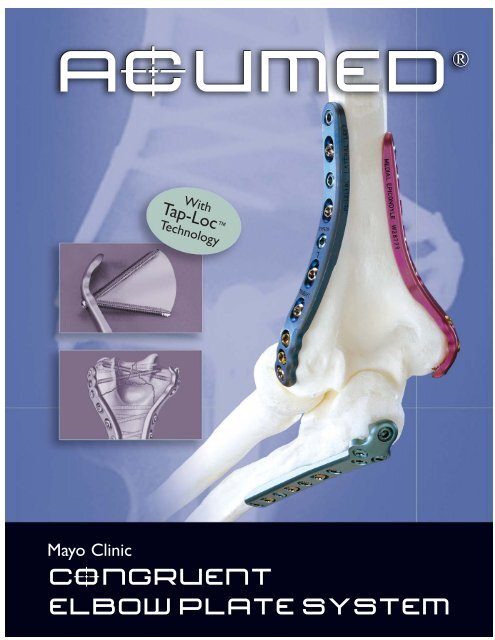
AcUMEDr<br />
Mayo Clinic<br />
With<br />
Tap-Loc <br />
Technology<br />
CoNGRUENT<br />
ELBOW PLATE SYSTEM
CoNGRUENT ELBOW PLATES<br />
Since 1988, <strong>Acumed</strong> has been<br />
designing solutions to the demanding<br />
situations facing orthopedic<br />
surgeons, hospitals and their<br />
patients. Our strategy has been<br />
to know the indication, design a<br />
solution to fit, and deliver quality<br />
products and instrumentation. The<br />
Mayo Clinic Congruent Elbow Plate<br />
System exemplifies this philosophy<br />
of quality and cutting-edge<br />
innovation.<br />
Designed to address fractures of<br />
the distal humerus, olecranon and<br />
coronoid, Mayo Clinic Congruent<br />
Elbow Plates offer pre-contoured,<br />
indication specific plates featuring<br />
variable angle Tap-Loc Technology.<br />
CONTENTS<br />
Introducing the System 2<br />
System Features 4<br />
The Plates<br />
Distal Humeral Plates 8<br />
Olecranon & Coronoid Plates 9<br />
Surgical Techniques<br />
Distal Humerus Surgical Technique 10<br />
Olecranon Surgical Technique 14<br />
Coronoid Surgical Technique 16<br />
Instrumentation & Biomechanical Data 18<br />
Ordering Information 19<br />
2<br />
Orthopedic surgeons are continually developing improved methods of<br />
fracture fixation and rehabilitation. <strong>Acumed</strong> recognizes that often these new<br />
fixation methods require changes and advancements in orthopedic implants<br />
and technology. Our goal is to design implants and instrumentation that<br />
address new fixation techniques, solve issues with current fixation methods<br />
and provide the best possible outcome for the patient.<br />
Mayo Clinic Congruent Elbow Plates, designed by Shawn O’Driscoll, Ph.D., M.D.,<br />
have revolutionized the way orthopedic surgeons treat and manage elbow<br />
fractures. Dr. O’Driscoll’s experience has shown that the “parallel” plate<br />
placement on the distal humerus, combined with increased plate strength over<br />
standard reconstruction plates1 , allows for early rehabilitation and preservation<br />
of elbow function and motion.<br />
<strong>Acumed</strong> believes that surgeons should have the ability to determine the<br />
trajectory of the locking screws in the distal humerus. This freedom offers the<br />
surgeon a means to maximize fixation in the distal fragments, providing the best<br />
possible outcome for the patient.
Pre-contoured Plates eliminate the need for the surgeon to bend<br />
the plates to match the anatomy of the patient. For complex<br />
fractures, the plates act as a template to restore the natural<br />
anatomic geometry of the distal humerus.<br />
Parallel Plate Placement provides a more stable construct than plates<br />
placed at a 90º orientation2 . Biomechanical data shows that parallel<br />
plate placement has greater strength and stability, especially when the<br />
elbow is subjected to A/P and torsional forces3 .<br />
Tap-Loc Technology allows the surgeon to angle the locking<br />
screws in the distal humerus up to 20° in each direction and<br />
create threads in the plate hole with a customized tap. This<br />
provides flexibility when capturing fracture fragments while<br />
maintaining the benefits of a traditional locking screw.<br />
Olecranon &<br />
Proximal Ulna<br />
Lateral Column<br />
Coronoid Posterior<br />
20°<br />
20°<br />
Medial Column<br />
3
4<br />
PRE-CONTOURED PLATES<br />
Mayo Clinic Congruent Elbow Plates are precontoured<br />
to match the natural anatomy of the<br />
elbow, minimizing the need for the surgeon to bend<br />
the plates prior to application. For complex fractures,<br />
the plates are able to act as a template for anatomic<br />
restoration of the elbow.<br />
Traditional straight plates weaken with repeated<br />
bending in the O.R. Pre-contoured plates offer a<br />
stronger alternative than straight reconstruction plates4 while maintaining a low profile. The design of the<br />
plates allows for maximum fixation and stability in the<br />
distal humerus and proximal ulna.<br />
Plates should maximize stability of periarticular fragments to<br />
facilitate rehabilitation.<br />
Clustered screw holes in the articular region increase stability and strength of<br />
the reconstruction. This improved stability allows the plates to compress these<br />
articular fragments with the shaft to achieve union of the fracture fragments.<br />
Plates should offer a low profile design to decrease irritation and<br />
hardware prominence.<br />
Plate profile and screw/plate interface were designed with the soft tissues<br />
in mind. The plates thin down in the periarticular region and the screw<br />
heads are recessed within the low profile plates.<br />
Plate thickness should be optimized for each region of the bone.<br />
Continuous change in thickness provides strength along the metaphysis/<br />
diaphysis where it is needed, while maintaining a low profile in the<br />
periarticular areas where limited soft tissue coverage may be an issue.
PARALLEL PLATE PLACEMENT<br />
The parallel placement of Mayo Clinic Congruent Elbow<br />
Plates provides a strong and stable construct so that the<br />
surgeon does not have to immobilize the elbow for an<br />
extended period post-op. The strength of the plates,<br />
along with the parallel application and locking technology,<br />
greatly reduces the chance of hardware failure. This<br />
also allows the patient to begin rehabilitation and range<br />
of motion exercises immediately after surgery.<br />
Because screws come from opposing sides of the<br />
condyles, long screws are able to interdigitate in the<br />
distal fragments, creating an “arch” construct. The<br />
interdigitating screws provide the keystone to the arch,<br />
creating a stable construct for immediate, aggressive<br />
rehabilitation.<br />
90º plate orientation was supported early on in a study<br />
that compared 90º plating to a Y-plate and crossed<br />
screws, but did not compare “perpendicular” to<br />
“parallel” plating5 . A second comprehensive study found<br />
“parallel” plating to be the best construct for reconstruction<br />
of a comminuted distal humerus6 . This study<br />
proved that plates placed in parallel configuration on<br />
the medial and lateral columns were stronger than 90º<br />
plating when a gap was present between the articular<br />
fragments and the shaft, as when the humerus is<br />
severely fractured.<br />
Both studies were written before the introduction of<br />
Mayo Clinic Congruent Elbow Plates, which optimize<br />
the biomechanics even further with their locking<br />
capability, placement and strength.<br />
5
6<br />
TAP-LoCt TECHNOLOGY<br />
Dr. O’Driscoll’s goal is to combine his principles for distal<br />
humeral fracture treatment with variable angle locking<br />
technology. Because anatomy and fracture patterns in the<br />
distal humerus vary from patient to patient, he saw the<br />
importance of allowing the surgeon to choose the angle of<br />
the distal locking screws. In addition, the locking threads of<br />
each locking screw should accurately coincide with the<br />
threads in the plate to ensure maximum locking strength<br />
and stability. Mayo Clinic Locking Distal Humeral Plates,<br />
featuring patented Tap-Loc Technology, offer the surgeon a<br />
system with these benefits as the next generation for the<br />
treatment of distal humeral fractures.<br />
With Mayo Clinic Congruent Elbow Plates, Dr. O’Driscoll<br />
has designed a system of pre-contoured plates that<br />
maximize fixation in the articular fragments, contributing<br />
to the stability of the entire reconstruction. These plates<br />
provide stability, allowing for aggressive rehabilitation<br />
beginning immediately after surgery.<br />
T-Handle<br />
provides control when<br />
tapping plate holes.<br />
3.5mm and 2.7mm plate tap<br />
sizes accommodate the screw<br />
diameters provided in the system.<br />
Quick Release<br />
instrumentation provides<br />
an efficient way to switch<br />
from 2.7mm to 3.5mm<br />
plate taps.
Multidirectional Screw Angles give the surgeon the<br />
freedom to angle the distal locking screws up to 20° in<br />
each direction. This provides flexibility when capturing<br />
fracture fragments while maintaining the benefits of a<br />
traditional locking screw.<br />
Tap Biomechanical Data shows that tapping a plate by<br />
hand does not result in a weaker screw-to-plate interface<br />
between the tapped hole and the locking screw when<br />
compared to a traditional locking plate7 .<br />
Targeted Drill Guide allows the surgeon to drill and<br />
position the distal screws with confidence and accuracy.<br />
The drill guide cannula is placed in the appropriate plate<br />
hole and the tip of the guide is positioned in the desirable<br />
location of the screws’ ending point.<br />
Laser Mark<br />
indicates maximum<br />
tapping depth.<br />
Tapping Threads<br />
allow the surgeon to tap the<br />
plate after drilling, creating<br />
threads in the plate and bone<br />
for locking screw insertion.<br />
Tap Trajectory Guide<br />
follows the drill path for<br />
accurate tap angle and<br />
screw placement.<br />
Traditional<br />
Locking<br />
Screw<br />
Tap-Loc<br />
Screw<br />
lbs.<br />
Tapping Instructions:<br />
29 lbs.<br />
Traditional<br />
Locking<br />
Screw<br />
35.6 lbs.<br />
Tap-Loc Screw<br />
Perpendicular .<br />
to Plate<br />
20°<br />
20°<br />
37.1 lbs.<br />
Tap-Loc<br />
Screw 20°to<br />
Plate<br />
• Do not tap deeper than the start of the laser line.<br />
• Clean debris from tap after tapping each hole.<br />
• Irrigate hole prior to tapping.<br />
• Do not tap a slot.<br />
• Do not re-tap a hole (use a non-locking screw).<br />
• Tap by hand, not under power.<br />
• Angle of tapped hole must not exceed 20°.<br />
7
8<br />
DISTAL HUMERUS PLATES<br />
Pre-contoured in three planes, the locking distal humerus plates<br />
offer multiple lengths and sizes to treat a wide variety of<br />
fractures.<br />
Lateral Column Plates<br />
These plates improve upon posterior plating biomechanically by<br />
enabling the use of longer screws that interdigitate with screws<br />
coming from the medial side. The lateral plates come in both<br />
lefts (blue) and rights (green) and are 11mm in width and<br />
2.0mm at the thickest point. Lengths range from 58mm to<br />
206mm.<br />
Medial Column Plates<br />
Distally these plates extend down to, or wrap around the<br />
medial epicondyle or even extend down onto the medial<br />
trochlea. Extending up the condylar ridge, these locking plates<br />
offer solid fixation and compression. This fixation is maximized<br />
when the screws in the articular fragments can interdigitate<br />
with those coming from the lateral side. The medial plates are<br />
11mm wide and 2.0mm at the thickest point and offer 2-4<br />
screw holes for fixation of the articular fragments. Lengths<br />
range from 84mm to 175mm.<br />
Technical Objectives for Locking Distal Humerus Plates:<br />
1. Every screw should pass through a plate.<br />
2. Each screw engages a fragment on the opposite side that is also attached to a plate.<br />
3. Each screw should be as long as possible.<br />
4. Each screw should engage as many fragments as possible.<br />
5. The screws in the distal fragments should lock together by interdigitation, creating a<br />
“fixed angle” structure.<br />
6. Plates should be applied such that compression is achieved at the supracondylar level<br />
for both columns.<br />
7. Plates must be strong and stiff enough to resist breaking or bending before union occurs.
Locking olecranon plates in the Mayo Clinic Congruent Elbow<br />
Plate System provide excellent fixation in the proximal ulna for<br />
both fractures and osteotomies. Prongs on the proximal tip of<br />
the plates provide provisional fixation into the triceps tendon,<br />
assisting with reduction and improving final stability. The plate is<br />
placed directly over the triceps tendon, eliminating the need for<br />
a triceps split. An extended plate without prongs is also offered<br />
for the treatment of fractures that extend proximally.<br />
Technical Objectives for Locking Olecranon Plates:<br />
1. Each screw should be as long as possible.<br />
2. Locking screws should interlock to provide a stable “fixed angle”<br />
structure inside the bone fragment.<br />
3. Plate should buttress against anterior pull of elbow flexors.<br />
4. Plate should provide stable fixation of the ulnar shaft.<br />
5. Plate should be applied with compression across the fracture.<br />
6. Plate must be strong and stiff enough to resist bending before<br />
union occurs.<br />
Mayo Clinic Congruent Coronoid Plates are offered in both<br />
standard and extended lengths. The standard size plates are<br />
indicated for fractures of the anteromedial facet of the coronoid.<br />
The plate acts as a buttress to the coronoid and counteracts the<br />
tendency of the elbow to subluxate. Threaded .035 and .045”<br />
titanium wires are included for supplementary fixation of the<br />
small coronoid fragments if necessary.<br />
An extended version of the plate is available for the treatment<br />
of coronoid fractures with associated distal comminution. The<br />
plate holes are elongated, allowing the surgeon to angle the<br />
screws to achieve a trajectory that adequately addresses individual<br />
fracture patterns.<br />
OLECRANON PLATES<br />
CORONOID PLATES<br />
9
10<br />
SURGICAL TECHNIQUE<br />
Distal Humerus Plates by Shawn O’Driscoll, Ph.D., M.D.<br />
This section offers <strong>Acumed</strong>’s suggested method for implanting the Distal Humerus Plates using Tap-Loc Technology. For specific questions<br />
not addressed here, please contact your local <strong>Acumed</strong> representative or <strong>Acumed</strong> at 888.627.9957.<br />
Step 1: Articular Fragment Reduction<br />
The articular fragments, which tend to be rotated toward each<br />
other in the axial plane, are reduced anatomically and provisionally<br />
held with .045” smooth K-wires (WS-1106ST). It is essential that<br />
these wires be placed close to the subchondral level to avoid<br />
interference with later screw placement, and away from where<br />
the plates will be placed on the lateral and medial columns<br />
(see Step 2). One or two strategically placed wires can then be<br />
used to provisionally hold the distal fragments in alignment with the<br />
humeral shaft.<br />
Step 3: Initial Proximal Screw Placement<br />
Insert a 3.5mm screw into a slotted hole of each plate proximal<br />
to the fracture site. Loosely tighten, allowing some freedom for<br />
the plate to move proximally during compression later. (Because<br />
the undersurface of each plate is tubular in the metaphyseal and<br />
diaphyseal regions, the screw in the slotted hole only needs to<br />
be tightened slightly to provide excellent provisional fixation of<br />
the entire distal humerus.) Bone taps (MS-LTT27/35) are recommended<br />
for patients with dense bone.<br />
Step 2: Plate Placement and Provisional Fixation<br />
The selected medial and lateral plates<br />
are placed and held apposed to the<br />
distal humerus, while one smooth<br />
2.0mm K-wire (WS-2009ST) is inserted<br />
through hole #2 (numbered from distal<br />
to proximal) of each plate through the<br />
epicondyles and across the distal fragments<br />
to maintain provisional fixation.<br />
These 2.0mm wires are left in place<br />
until after Step 7 to simplify placing the<br />
locking screws in the distal fragments.<br />
The distal tap locking screws are able to<br />
be angled up to 20° in any direction.<br />
A tap screw angle guide (MS-TAG20) is<br />
included in the system to verify proper<br />
angulation prior to inserting the 2.0mm<br />
wires, which will later be replaced with<br />
locking screws. Place the angle guide<br />
next to the plate hole when inserting<br />
the wire to verify that the angle is equal<br />
to or less than 20°.<br />
A targeted drill guide (PL-CLAMP) is<br />
available in the system for accurate<br />
placement of the 2.0mm wires and<br />
future distal screws. Place the 2.0mm<br />
cannula (PL-20CLAMP) through the<br />
drill guide and into the plate hole. The<br />
opposing end of the guide is placed at<br />
the desired exiting point of the wire.<br />
A 2.8mm cannula (PL-28CLAMP) is<br />
also available for accurate drilling and<br />
placement of 3.5mm screws in later steps.
Step 4: Non-Locking Distal Screw Placement<br />
Drill and insert screws through hole #1 on both the medial and<br />
lateral side. The targeted drill guide cannot be used in hole #1 of<br />
the medial plate if the angle of the non-locking screw exceeds 20°.<br />
After drilling, measure depth and insert the appropriate size screw.<br />
3.5mm cortical screws are recommended. The 2.7mm screws may<br />
be used in patients with osteoporotic bone to enable more screws<br />
to be placed in the distal fragments to maximize stability.<br />
Long drills (MS-LDC20/28) and quick release pins (MS-PIN20/28)<br />
are meant to be used with the targeted drill guide. As more screws<br />
are inserted into the distal fragments in later steps, the quick<br />
release pins may be used in place of the long drills to glide past<br />
previously inserted screws.<br />
Step 6: Compress Medial Column<br />
The medial column is then compressed in a similar manner using<br />
the large tenaculum (MS-1280), and a 3.5mm non-locking (CO-<br />
3XX0) screw is inserted in the medial plate in dynamic compression<br />
mode in a slotted hole proximal to the fracture site, using<br />
the offset drill guide (PL-2095). If the plates are slightly under<br />
contoured, they can be compressed against the metaphysis with a<br />
large bone clamp, giving further supracondylar compression.<br />
Remove the 2.0mm wires that were inserted in Step 2.<br />
Step 5: Compress Lateral Column<br />
Using a large tenaculum (MS-1280) to provide interfragmentary<br />
compression across the fracture at the supracondylar level, the<br />
lateral column is first fixed. A screw is inserted in the lateral plate<br />
in dynamic compression mode in a slotted hole proximal to the<br />
fracture site (image inset) using the offset drill guide (PL-2095).<br />
Tightening this further enhances interfragmentary compression at<br />
the supracondylar level (converging arrows) to the point of causing<br />
some distraction at the medial supracondylar ridge (diverging<br />
arrows). The .045” wires used for provisional fixation may be<br />
removed at this point.<br />
Note: The proximal slotted holes are NOT to be tapped.<br />
Technical Objectives Checklist:<br />
Every screw should pass through a plate.<br />
Each screw engages a fragment on the<br />
opposite side that is also attached to a plate.<br />
Each screw should be as long as possible.<br />
Each screw should engage as many fragments<br />
as possible.<br />
The screws in the distal fragments should<br />
lock together by interdigitation, creating a<br />
“fixed angle” structure.<br />
Plates should be applied such that<br />
compression is achieved at the supracondylar<br />
level for both columns.<br />
Plates must be strong and stiff enough to resist<br />
breaking or bending before union occurs.<br />
11
12<br />
Distal Humerus Plates (cont.)<br />
Step 7: Tap Distal Plate Hole<br />
If using a 3.5mm screw, use the 2.8mm drill or smooth quick<br />
release pin in the path of the wire. If using a 2.7mm screw (osteoporotic<br />
bone), the 2.0mm wire has already created the appropriate<br />
size hole for the screw. Measure drill depth (MS-9022) to determine<br />
screw size. After drilling, connect the tap (PL-ELT1027/35) to<br />
the T-Handle (MS-T1212) and tap the plate. The front end of the<br />
tap will act as a guide to ensure that the locking screw follows the<br />
correct trajectory. Turning the tap one-half turn at a time, tap the<br />
plate taking care not to insert the tap further than the start of the<br />
laser line on the tap threads. (See Tapping Instructions)<br />
Note: The T-Handle (MS-T1212) should only be used with the<br />
plate taps and not for locking or non-locking screw insertion.<br />
Step 8: Insert Distal Locking Screw<br />
Insert the appropriate size tap locking screw. Care should be taken<br />
to not overtighten the screw.<br />
The #3 holes on both the medial and lateral columns are optional.<br />
However, if these holes are used be sure to use locking screws if<br />
locking screws have already been inserted in previous steps.<br />
<strong>Acumed</strong> Single Use Tapping<br />
Instrument Precautions:<br />
Tapping a plate using a plate tap will cause titanium<br />
debris to be generated, which should be removed.<br />
Failure to remove the plate debris can cause, among<br />
other complications, inflammation, cartilage damage,<br />
and patient discomfort. The taps are single surgery<br />
use and should be discarded after each surgery or if<br />
the tap becomes dull or damaged. If the resistance<br />
increases while using a tap, discard the tap immediately.<br />
Breakage to the tap can occur due to excessive<br />
torque or levering and care should be taken to avoid<br />
such conditions. Should breakage occur, carefully<br />
remove all tap pieces.<br />
Tapping Instructions:<br />
• Do not tap deeper than the start of the laser line.<br />
• Clean debris from tap after tapping each hole.<br />
• Irrigate hole prior to tapping.<br />
• Do not tap a slot.<br />
• Do not re-tap a hole (use a non-locking screw).<br />
• Tap by hand, not under power.<br />
• Angle of tapped hole must not exceed 20°.<br />
Step 9A: Drill for Proximal Locking Screw<br />
The remaining locking shaft screws may be inserted at the<br />
surgeon’s discretion. To insert the 2.7mm or 3.5mm locking shaft<br />
screws (COL-xxx0), thread the appropriate size locking drill guide<br />
(MS-LDG27/35) into the locking hole in the plate. Drill with the<br />
appropriate size drill (MS-DC5020 or MS-DC28).
Step 9B: Insert Proximal Locking Screw<br />
Insert the appropriate size shaft locking screw (COL-xxx0).<br />
Note that the plate holes in the humeral shaft are pre-threaded,<br />
fixed angle screws.<br />
Step10: Final Screw Placement<br />
The remaining locking shaft screws may be inserted at the<br />
surgeon’s discretion.<br />
Screw Diameter Drill Diameter<br />
2.7mm 2.0mm<br />
3.5mm<br />
4.0mm<br />
2.8mm<br />
Post-op Protocol:<br />
Immediately after closure, the elbow is placed<br />
in a bulky non-compressive Jones dressing with<br />
an anterior plaster slab to maintain the elbow<br />
in extension, and the upper extremity is kept<br />
elevated. The initial rehabilitation is planned<br />
according to the extent of soft-tissue damage.<br />
When the fracture is associated with severe<br />
soft-tissue damage, the extremity is kept<br />
immobilized and elevated with the elbow in<br />
extension for 3-7 days postoperatively. If the<br />
fracture is closed and there is no severe<br />
swelling or fracture blisters, the Jones dressing<br />
is removed after two days and an elastic nonconstrictive<br />
sleeve is applied over an absorbent<br />
dressing placed on the wound. A physical therapy<br />
program including active and passive<br />
motion is then initiated.<br />
13
14<br />
SURGICAL TECHNIQUE<br />
Olecranon Plate by Shawn O’Driscoll, Ph.D., M.D.<br />
This section offers <strong>Acumed</strong>’s suggested method for implanting the Locking Olecranon Plate from the Mayo Clinic Congruent<br />
Elbow Plate System. For specific questions not addressed here, please contact your local <strong>Acumed</strong> representative or <strong>Acumed</strong> by<br />
phone at (888) 627-9957 or on the web at www.acumed.net.<br />
1: Flex the elbow 90°, reduce the fracture and apply the<br />
plate. The prongs in the proximal end of the plate should<br />
penetrate the triceps tendon and provide provisional fixation.<br />
These prongs do not compress the tendon, and a gap<br />
between the plate and the bone should be visible on X-ray.<br />
3: With provisional reduction confirmed, drill (MS-DC28)<br />
and insert a 3.5mm non-locking screw (CO-3xx0) through<br />
the slotted hole distal to the fracture site and into the ulnar<br />
shaft. Connect the 2.5mm hex driver tip (HPC-0025) to the<br />
driver handle (MS-3200 or MS-1210) and tighten the screw<br />
partially to allow for later compression.<br />
Bone taps (MS-LTT27/35) are recommended for patients<br />
with dense bone.<br />
2: A 2.0mm wire (WS-2009ST) is drilled through the proximal<br />
hole of the plate and across the fracture site, penetrating<br />
the anterior metaphyseal cortex. If a locking screw is to be<br />
utilized, thread the 2.7mm locking drill guide (MS-LDG27)<br />
into the plate hole and then insert the wire. Do not remove<br />
this wire until Step 6.<br />
Alternatively, two .062" wires can be placed across the<br />
fracture, one on each side of the plate.<br />
4: Insert a 3.5mm non-locking screw (CO-3xx0) in dynamic<br />
compression mode into a distal slot along the ulnar shaft<br />
using the offset drill guide (PL-2095). The proximal shaft<br />
screw may be loosened to allow for compression. If a longer<br />
plate is used and further compression is required, insert<br />
another non-locking screw into a distal slot in dynamic compression<br />
mode, loosening the first two screws to allow for<br />
plate movement.
5: Insert two 2.7mm locking screws (COL-2xx0) into the<br />
proximal holes on either side of the 2.0mm wire, using the<br />
2.7mm locking drill guide (MS-LDG27). When drilling (MS-<br />
DC5020), be careful not to exit the bone. The fixed angle<br />
locking screw trajectory is meant to create maximum<br />
fixation in the small proximal fragments.<br />
7: The remaining screws are inserted at the surgeon’s<br />
discretion. If a locking screw is used in the most proximal of<br />
the distal plate holes, the screw must be short enough (max.<br />
16mm) to avoid contact with the locking “home run” screw.<br />
If a longer screw is necessary, use a non-locking screw and<br />
angle it slightly to avoid contact with the locking “home run”<br />
screw. A non-locking screw must be used in the most distal<br />
of the proximal cluster of holes to avoid contacting the<br />
locking “home run” screw.<br />
6: Remove the 2.0mm wire and insert a locking 3.5mm<br />
(COL-3xx0),“home run” screw. Attach the 3.5mm locking<br />
drill guide and use the 2.8mm long drill (MS-LDC28) in the<br />
path of the wire. Measure depth and insert the screw.<br />
If using a non-locking 2.7mm “home run” screw, the 2.0mm<br />
wire has already created the appropriate size hole and<br />
trajectory for the locking screw.<br />
Post-op Protocol:<br />
Immediately after closure, the elbow is placed in a bulky<br />
non-compressive Jones dressing with an anterior plaster slab<br />
to maintain the elbow in extension, and the upper extremity<br />
is kept elevated. The initial rehabilitation is planned according<br />
to the extent of soft-tissue damage. When the fracture is<br />
associated with severe soft-tissue damage, the extremity is<br />
kept immobilized and elevated with the elbow in extension<br />
for 3-7 days postoperatively. If the fracture is closed and<br />
there is no severe swelling or fracture blisters, the Jones<br />
dressing is removed after two days and an elastic non-constrictive<br />
sleeve is applied over an absorbent dressing placed<br />
on the wound. A physical therapy program including active<br />
and passive motion is then initiated.<br />
15
16<br />
SURGICAL TECHNIQUE<br />
Coronoid Plate by Shawn O’Driscoll, Ph.D., M.D.<br />
This section offers <strong>Acumed</strong>’s suggested method for implanting the Coronoid Plate from the Mayo Clinic Congruent Elbow<br />
Plate System. For specific questions not addressed here, please contact your local <strong>Acumed</strong> representative or <strong>Acumed</strong> by phone<br />
at (888) 627-9957 or on the web at www.acumed.net.<br />
1: Expose the coronoid through an anteriomedial<br />
approach. Reduce and provisionally hold the fragments<br />
with threaded titanium wires (WT-xx0xSTT) drilled from<br />
posterior to anterior. These are best placed when retracting<br />
the coronoid fragments, so that you can see the wires<br />
emerge into the fracture surface. They are then backed past<br />
the fracture site to allow for reduction. Once a proper<br />
reduction is achieved, re-advance the wires past the fracture<br />
site and into the fragments.<br />
3: While holding the plate reduced, drill the middle hole<br />
(MS-DC5020) and insert a 2.7mm screw (CO-27xx). Do<br />
not tighten the screw.<br />
Bone taps (MS-LTT27/35) are recommended for patients<br />
with dense bone.<br />
2: Apply the Mayo Clinic Congruent Coronoid Plate so<br />
that the sharp prongs grasp and buttress the section of the<br />
coronoid between its tip and its sublime tubercle on which<br />
the anterior bundle of the MCL inserts. The plate should<br />
wrap around the brachialis tendon insertion onto the medial<br />
side of the ulna distally.<br />
4: Push the distal tip of the plate anteriorly, applying a lever<br />
force against the coronoid fragments, and insert a 2.7mm<br />
screw (CO-27xx) through the distal hole. Do not tighten<br />
the screw.
5: Tighten the proximal screw to bring the midsection of<br />
the plate to the bone and fully secure the buttress against<br />
the coronoid fragments. Tighten the distal screw. The plate<br />
will flex and contour to follow the line of the bone as this<br />
final screw is tightened.<br />
6: Cut the threaded titanium wires flush with the ulna,<br />
eliminating soft tissue irritation.<br />
Note: If buttressing is excellent, the wires can be removed.<br />
If they are to be left in they must be titanium and threaded<br />
(WT-xx0xSTT), not smooth.<br />
Post-op Protocol:<br />
Immediately after closure, the elbow is placed in a bulky<br />
non-compressive Jones dressing with an anterior plaster slab<br />
to maintain the elbow in extension, and the upper extremity<br />
is kept elevated. The initial rehabilitation is planned according<br />
to the extent of soft-tissue damage. When the fracture<br />
is associated with severe soft-tissue damage, the extremity is<br />
kept immobilized and elevated with the elbow in extension<br />
for 3-7 days postoperatively. If the fracture is closed and<br />
there is no severe swelling or fracture blisters, the Jones<br />
dressing is removed after two days and an elastic<br />
non-constrictive sleeve is applied over an absorbent dressing<br />
placed on the wound.<br />
In cases in which fracture stability is not a concern, a program<br />
of continuous passive motion begins within the limits<br />
of motion determined by soft tissue compliance, which itself<br />
is diminished due to fluid accumulation at the elbow region.<br />
Edema control is important postoperatively, as swelling limits<br />
elbow motion. It is essential that gravitational varus stresses<br />
are avoided, as these will result in displacement of the medial<br />
coronoid fracture fragment. Therefore, the arm is maintained<br />
in a vertical plane when the elbow is being moved<br />
and supporting the wrist whenever the arm is moved away<br />
from the body unloads the weight of the forearm. Both<br />
active and passive motion are permissible in most coronoid<br />
fractures that have been treated with the technique just<br />
described.<br />
If by 4-6 weeks motion is not returning satisfactorily, a program<br />
of patient-adjusted static flexion and extension splinting<br />
should be commenced to assist with regaining motion. If<br />
heterotopic ossification is forming, the splinting program<br />
should still be used. The forces generated are small, and not<br />
a risk of worsening the heterotopic ossification.<br />
17
18<br />
INSTRUMENTATION<br />
In addition to the innovative features of the Mayo<br />
Clinic Congruent Elbow Plates, <strong>Acumed</strong> designed<br />
the instrumentation set for ease of use by including<br />
everything the surgeon needs for the case in a<br />
well organized tray.<br />
A custom targeted drill guide is included in the<br />
system to provide an accurate and efficient means<br />
of targeting the trajectory of the screws in the<br />
distal humerus. A cannula is placed through the<br />
drill guide and into the selected plate hole. The<br />
opposing end of the drill guide is then placed at<br />
the desired exiting point of the screw.<br />
A Tap Screw Angle Guide is also included in the<br />
system to verify proper angulation of the Tap-Loc<br />
Screws prior to drilling the bone and tapping the<br />
plate. The angle guide is placed next to the plate<br />
hole when inserting a wire or drill to verify that<br />
the angle is equal to or less than 20°.<br />
Biomechanical Testing<br />
Early biomechanical testing done in a finite element analysis program at <strong>Acumed</strong> indicate significant advantages of<br />
parallel plating versus 90º plating8. For this study, a computer modeled a distal humerus fracture and assumed equivalent<br />
plate fixation and strength (two areas in which Mayo Clinic Congruent Elbow Plates are significantly better than<br />
90º plating with reconstruction or tubular plates). The program simulated a load of 50 lbs. in three different planes:<br />
A/P, M/L, and Torsion. The results supported parallel plating, especially in torsional loads.<br />
90º Plating Displaced<br />
Anterior/Posterior: 53% more<br />
Medial/Lateral: 5% less<br />
Torsion: 80% more<br />
Parallel Plating Perpendicular Plating
Mayo Clinic Congruent Elbow Plates<br />
PL-LEM16 16 Hole Locking Medial Plate<br />
PL-LEM12 12 Hole Locking Medial Plate<br />
PL-LEM9L 9 Hole, Long Locking Medial Plate<br />
PL-LEM9S 9 Hole, Short Locking Medial Plate<br />
PL-LEM8 8 Hole Locking Medial Plate<br />
PL-LEM7 7 Hole Locking Medial Plate<br />
PL-LEL20L 20 Hole Left Locking Lateral Plate<br />
PL-LEL20R 20 Hole Right Locking Lateral Plate<br />
PL-LEL14L 14 Hole Left Locking Lateral Plate<br />
PL-LEL14R 14 Hole Right Locking Lateral Plate<br />
PL-LEL10L 10 Hole Left Locking Lateral Plate<br />
PL-LEL10R 10 Hole Right Locking Lateral Plate<br />
PL-LEL6L 6 Hole Left Locking Lateral Plate<br />
PL-LEL6R 6 Hole Right Locking Lateral Plate<br />
PL-LEO17L 17 Hole Left Locking Olecranon Plate<br />
PL-LEO17R 17 Hole Right Locking Olecranon Plate<br />
PL-LEO13 13 Hole Locking Olecranon Plate<br />
PL-LEO13E 13 Hole Extended Locking Olecranon Plate<br />
PL-LEO11 11 Hole Locking Olecranon Plate<br />
PL-LEO9 9 Hole Locking Olecranon Plate<br />
PL-ELCOL Coronoid Plate Left<br />
PL-ELCOR Coronoid Plate Right<br />
PL-ELCLL Extended Coronoid Plate Left<br />
PL-ELCLR Extended Coronoid Plate Right<br />
PL-ELPO Posterior Plate<br />
2.7mm Locking Cortical Screws<br />
COL-2120 2.7mm x 12mm<br />
COL-2140 2.7mm x 14mm<br />
COL-2160 2.7mm x 16mm<br />
COL-2180 2.7mm x 18mm<br />
COL-2200 2.7mm x 20mm<br />
COL-2220 2.7mm x 22mm<br />
Instruments<br />
AcUMEDr<br />
5885 N.W. Cornelius Pass Road, Hillsboro, OR 97124<br />
(888) 627-9957 www.acumed.net<br />
ORDERING INFORMATION<br />
WT-1606STT .062” x 6” Threaded Titanium Wire<br />
WT-0906STT .035” x 6” Threaded Titanium Wire<br />
WS-1106ST .045” x 6” SS Guide Wire<br />
WS2009ST 2.0mm x 9” Guide Wire<br />
MS-DC5020 2.0mm Quick Release Drill<br />
MS-DC28 2.8mm Quick Release Drill<br />
MS-DC35 3.5mm Quick Release Drill<br />
MS-LDC20 Dia 2.0mm Long Quick Release Drill<br />
MS-LDC28 Dia 2.8mm Long Quick Release Drill<br />
MS-PIN20 Dia 2.0mm Long Quick Release Pin<br />
MS-PIN28 Dia 2.8mm Long Quick Release Pin<br />
PL-ELT1027 2.7mm Quick Release Plate Tap<br />
PL-ELT1035 3.5mm Quick Release Plate Tap<br />
MS-LTT27 2.7mm Long Tap Tip (Bone Tap)<br />
MS-LTT35 3.5mm Long Tap Tip (Bone Tap)<br />
HPC-0025 2.5mm Quick Release Driver<br />
3.5mm Locking Cortical Screws<br />
COL-3120 3.5mm x 12mm<br />
COL-3140 3.5mm x 14mm<br />
COL-3160 3.5mm x 16mm<br />
COL-3180 3.5mm x 18mm<br />
COL-3200 3.5mm x 20mm<br />
COL-3220 3.5mm x 22mm<br />
COL-3240 3.5mm x 24mm<br />
COL-3260 3.5mm x 26mm<br />
COL-3280 3.5mm x 28mm<br />
COL-3300 3.5mm x 30mm<br />
COL-3320 3.5mm x 32mm<br />
COL-3340 3.5mm x 34mm<br />
COL-3360 3.5mm x 36mm<br />
COL-3380 3.5mm x 38mm<br />
COL-3400 3.5mm x 40mm<br />
COL-3450 3.5mm x 45mm<br />
COL-3500 3.5mm x 50mm<br />
3.5mm Cortical Screws<br />
CO-3120 3.5mm x 12mm<br />
CO-3140 3.5mm x 14mm<br />
CO-3160 3.5mm x 16mm<br />
CO-3180 3.5mm x 18mm<br />
CO-3200 3.5mm x 20mm<br />
CO-3220 3.5mm x 22mm<br />
CO-3240 3.5mm x 24mm<br />
CO-3260 3.5mm x 26mm<br />
CO-3280 3.5mm x 28mm<br />
CO-3300 3.5mm x 30mm<br />
CO-3320 3.5mm x 32mm<br />
CO-3340 3.5mm x 34mm<br />
CO-3360 3.5mm x 36mm<br />
CO-3380 3.5mm x 38mm<br />
CO-3400 3.5mm x 40mm<br />
CO-3450 3.5mm x 45mm<br />
CO-3500 3.5mm x 50mm<br />
CO-3550 3.5mm x 55mm<br />
CO-3600 3.5mm x 60mm<br />
CO-3650 3.5mm x 65mm<br />
2.7mm Tap Locking Screws<br />
FA-CO2736 2.7mm x 36mm<br />
FA-CO2738 2.7mm x 38mm<br />
FA-CO2740 2.7mm x 40mm<br />
FA-CO2745 2.7mm x 45mm<br />
FA-CO2750 2.7mm x 50mm<br />
FA-CO2755 2.7mm x 55mm<br />
3.5mm Tap Locking Screws<br />
FA-CO3536 3.5mm x 36mm<br />
FA-CO3538 3.5mm x 38mm<br />
FA-CO3540 3.5mm x 40mm<br />
FA-CO3545 3.5mm x 45mm<br />
FA-CO3550 3.5mm x 50mm<br />
FA-CO3555 3.5mm x 55mm<br />
FA-CO3560 3.5mm x 60mm<br />
2.7mm Cortical Screws<br />
CO-2712 2.7mm x 12mm<br />
CO-2714 2.7mm x 14mm<br />
CO-2716 2.7mm x 16mm<br />
CO-2718 2.7mm x 18mm<br />
CO-2720 2.7mm x 20mm<br />
CO-2722 2.7mm x 22mm<br />
CO-2724 2.7mm x 24mm<br />
CO-2726 2.7mm x 26mm<br />
CO-2728 2.7mm x 28mm<br />
CO-2730 2.7mm x 30mm<br />
CO-2732 2.7mm x 32mm<br />
CO-2734 2.7mm x 34mm<br />
CO-2736 2.7mm x 36mm<br />
CO-2738 2.7mm x 38mm<br />
CO-2740 2.7mm x 40mm<br />
CO-2745 2.7mm x 45mm<br />
CO-2750 2.7mm x 50mm<br />
CO-2755 2.7mm x 55mm<br />
CO-2760 2.7mm x 60mm<br />
CO-2765 2.7mm x 65mm<br />
4.0mm Cancellous Screws<br />
CA-4120 4.0mm x 12mm<br />
CA-4140 4.0mm x 14mm<br />
CA-4160 4.0mm x 16mm<br />
CA-4180 4.0mm x 18mm<br />
CA-4200 4.0mm x 20mm<br />
CA-4220 4.0mm x 22mm<br />
CA-4240 4.0mm x 24mm<br />
CA-4260 4.0mm x 26mm<br />
CA-4280 4.0mm x 28mm<br />
CA-4300 4.0mm x 30mm<br />
CA-4350 4.0mm x 35mm<br />
CA-4400 4.0mm x 40mm<br />
CA-4450 4.0mm x 45mm<br />
CA-4500 4.0mm x 50mm<br />
CA-4550 4.0mm x 55mm<br />
CA-4600 4.0mm x 60mm<br />
19
AcUMEDr<br />
5885 N.W. Cornelius Pass Road<br />
Hillsboro, OR 97124<br />
(888) 627-9957<br />
www.acumed.net<br />
Copyright © 2006<br />
<strong>Acumed</strong> is a registered trademark.<br />
All rights reserved.<br />
Patents pending.<br />
CPS00-01-04 Effective: 05/2007<br />
1. Data on file at <strong>Acumed</strong>.<br />
2. "Biomechanical Evaluation of Methods of Internal Fixation<br />
of the Distal Humerus,” Schemitsch,Tencer and Henley,<br />
Journal of Orthopaedic Trauma, 1994.<br />
3. Data on file at <strong>Acumed</strong>.<br />
4. Data on file at <strong>Acumed</strong>.<br />
5. "Internal Fixation of the Distal Humerus: A Biomechanical<br />
Comparison of Methods," Helfet and Hotchkiss, Journal of<br />
Orthopaedic Trauma, 1990.<br />
6. "Biomechanical Evaluation of Methods of Internal Fixation<br />
of the Distal Humerus,” Schemitsch,Tencer and Henley,<br />
Journal of Orthopaedic Trauma, 1994.<br />
7. Data on file at <strong>Acumed</strong>.<br />
8. Data on file at <strong>Acumed</strong>.