30023403030 7118-1161 per-loc dist hum plate st_INT'L.9.4.qxp
30023403030 7118-1161 per-loc dist hum plate st_INT'L.9.4.qxp
30023403030 7118-1161 per-loc dist hum plate st_INT'L.9.4.qxp

Create successful ePaper yourself
Turn your PDF publications into a flip-book with our unique Google optimized e-Paper software.
Surgical Technique<br />
International Version<br />
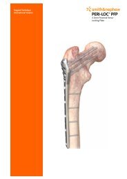
Di<strong>st</strong>al Humerus Locking Plate
PERI-LOC Up<<strong>st</strong>rong>per</<strong>st</strong>rong> Extremity<br />
Locked Plating Sy<strong>st</strong>em<br />
Di<strong>st</strong>al Humerus Surgical Technique<br />
Table of Contents<br />
Introduction . . . . . . . . . . . . . . . . . . . . . . . . . . . . . . . . . . . . . . . . . . . . . . . . . . . . .2<br />
PERI-LOC Locked Plating Sy<strong>st</strong>em Overview . . . . . . . . . . . . . . . . . . . . . . . . . . . . .2<br />
Implant Features . . . . . . . . . . . . . . . . . . . . . . . . . . . . . . . . . . . . . . . . . . . . . . . . . .4<br />
Indications . . . . . . . . . . . . . . . . . . . . . . . . . . . . . . . . . . . . . . . . . . . . . . . . . . . . . . .5<br />
Di<strong>st</strong>al Humerus Case Examples . . . . . . . . . . . . . . . . . . . . . . . . . . . . . . . . . . . . . .6<br />
Surgical Technique . . . . . . . . . . . . . . . . . . . . . . . . . . . . . . . . . . . . . . . . . . . . . . . .7<br />
Patient Positioning . . . . . . . . . . . . . . . . . . . . . . . . . . . . . . . . . . . . . . . . . . . . . . . . .7<br />
Incision . . . . . . . . . . . . . . . . . . . . . . . . . . . . . . . . . . . . . . . . . . . . . . . . . . . . . . . . . .8<br />
Fracture Reduction and Provisional Fixation . . . . . . . . . . . . . . . . . . . . . . . . . . . . .9<br />
Plate Selection . . . . . . . . . . . . . . . . . . . . . . . . . . . . . . . . . . . . . . . . . . . . . . . . . . . .10<br />
Plate Positioning . . . . . . . . . . . . . . . . . . . . . . . . . . . . . . . . . . . . . . . . . . . . . . . . . .12<br />
Screw Insertion . . . . . . . . . . . . . . . . . . . . . . . . . . . . . . . . . . . . . . . . . . . . . . . . . . . .13<br />
• 2.7mm Cortex/Locking Screw Technique . . . . . . . . . . . . . . . . . . . . . . . . . . . . . . .14<br />
• 3.5mm Cortex/Locking Screw Technique . . . . . . . . . . . . . . . . . . . . . . . . . . . . . . .16<br />
Incision Closure . . . . . . . . . . . . . . . . . . . . . . . . . . . . . . . . . . . . . . . . . . . . . . . . . . .18<br />
Catalogue Information . . . . . . . . . . . . . . . . . . . . . . . . . . . . . . . . . . . . . . . . . . . . .19<br />
Nota Bene<br />
The technique description herein is made available to the healthcare professional<br />
to illu<strong>st</strong>rate the author's sugge<strong>st</strong>ed treatment for the uncomplicated procedure.<br />
In the final analysis, the preferred treatment is that which addresses the needs of<br />
the specific patient.<br />
1
Introduction<br />
PERI-LOC Locked Plating Sy<strong>st</strong>em<br />
Overview<br />
The PERI-LOC Locked Plating Sy<strong>st</strong>em combines<br />
the advantages of <<strong>st</strong>rong>loc</<strong>st</strong>rong>ked plating with<br />
the flexibility and benefits of traditional <<strong>st</strong>rong>plate</<strong>st</strong>rong>s<br />
and screws. Utilising both <<strong>st</strong>rong>loc</<strong>st</strong>rong>king and non<<strong>st</strong>rong>loc</<strong>st</strong>rong>king<br />
screws, the PERI-LOC sy<strong>st</strong>em allows<br />
for the creation of a con<strong>st</strong>ruct that resi<strong>st</strong>s<br />
angular collapse and also functions as an<br />
effective fracture reduction aid. A simple, intuitive<br />
in<strong>st</strong>rument set featuring <strong>st</strong>andardised drill<br />
bits, screwdrivers, and colour coded drill<br />
guides helps make the PERI-LOC sy<strong>st</strong>em efficient<br />
and easy to use.<br />
The precise screw trajectories, anatomic contour,<br />
and <<strong>st</strong>rong>loc</<strong>st</strong>rong>king capabilities of the PERI-LOC<br />
Di<strong>st</strong>al Humerus Plates provide a <strong>st</strong>able con<strong>st</strong>ruct<br />
for predictable recon<strong>st</strong>ruction of complex<br />
fractures of the <<strong>st</strong>rong>hum</<strong>st</strong>rong>erus.<br />
2
• Three (3) <<strong>st</strong>rong>plate</<strong>st</strong>rong> options: Lateral, Medial, and<br />
Po<strong>st</strong>erolateral<br />
• Low profile <<strong>st</strong>rong>plate</<strong>st</strong>rong> and screws reduce the<br />
potential for soft tissue and tendon irritation<br />
• Compression-to-recon <<strong>st</strong>rong>plate</<strong>st</strong>rong> profile transition<br />
facilitates additional intrao<<strong>st</strong>rong>per</<strong>st</strong>rong>ative contouring<br />
• Sy<strong>st</strong>em configuration allows for either 90°- 90°<br />
or 180° plating techniques<br />
• Left and right specific <<strong>st</strong>rong>plate</<strong>st</strong>rong>s available in a<br />
variety of lengths for precise implant contour<br />
• 316L <strong>st</strong>ainless <strong>st</strong>eel for <strong>st</strong>rength<br />
• Bevelled <<strong>st</strong>rong>plate</<strong>st</strong>rong> tip for <<strong>st</strong>rong>per</<strong>st</strong>rong>cutaneous insertion<br />
• 2.7mm <<strong>st</strong>rong>di<strong>st</strong></<strong>st</strong>rong>al <<strong>st</strong>rong>loc</<strong>st</strong>rong>king screws provide optimal,<br />
low profile articular fixation<br />
• Curved <<strong>st</strong>rong>plate</<strong>st</strong>rong> design maximises shaft coverage<br />
while avoiding sensitive neuro-anatomy<br />
• Locking and non-<<strong>st</strong>rong>loc</<strong>st</strong>rong>king option in every hole<br />
for cu<strong>st</strong>om screw configurations<br />
3
Implant Features<br />
Bevelled<br />
tip for <<strong>st</strong>rong>per</<strong>st</strong>rong>cutaneousinsertion<br />
2.7mm<br />
articular<br />
screws<br />
4<br />
Medial Plate<br />
Po<strong>st</strong>erolateral<br />
Plate<br />
Every threaded hole can accept a <<strong>st</strong>rong>loc</<strong>st</strong>rong>king or non-<<strong>st</strong>rong>loc</<strong>st</strong>rong>king screw:<br />
2.7mm Self-tapping Cortex Screw (Non-<<strong>st</strong>rong>loc</<strong>st</strong>rong>king)<br />
Cat. No. 7180-30XX<br />
Lateral Plate<br />
2.7mm Locking Self-tapping Cortex Screw<br />
Cat. No. 7180-23XX<br />
Recon <<strong>st</strong>rong>plate</<strong>st</strong>rong><br />
design for easy<br />
contouring<br />
3.5mm Screw<br />
Holes
Indications<br />
The PERI-LOC Di<strong>st</strong>al Humerus Plates are<br />
indicated for fixation of fractures, non-unions<br />
and o<strong>st</strong>eotomies of the <<strong>st</strong>rong>hum</<strong>st</strong>rong>erus.<br />
5
Di<strong>st</strong>al Humerus Case Example<br />
Case 1<br />
6
Surgical Technique<br />
Patient Positioning<br />
The patient may be placed in either the lateral,<br />
prone, or supine position with the involved<br />
limb supported over bol<strong>st</strong>ers or an elevated<br />
arm board placed parallel to the table. A<br />
radiolucent table and arm board are preferable<br />
so as not to impede fluoroscopy.<br />
7
Incision<br />
A <strong>st</strong>raight, po<strong>st</strong>erior longitudinal incision is<br />
made curving ju<strong>st</strong> lateral to the olecranon<br />
process. Full thickness skin flaps are developed<br />
medially and laterally. The method for<br />
exposing the articular surface depends upon<br />
the degree of articular comminution present<br />
and surgeon preference. Exposure of the articular<br />
fracture fragments is typically accomplished<br />
by either an Olecranon O<strong>st</strong>eotomy or<br />
a Triceps Split. These approaches may provide<br />
improved access to the <<strong>st</strong>rong>di<strong>st</strong></<strong>st</strong>rong>al <<strong>st</strong>rong>hum</<strong>st</strong>rong>erus and<br />
decrease some of the complications associated<br />
with comminuted fractures.<br />
8
Fracture Reduction and Provisional<br />
Fixation<br />
After exposure and debridement of the fracture<br />
site, the fracture is reduced and provisionally<br />
fixed under fluoroscopy with K-wires, reduction<br />
forceps or suture fixation. Reduction aids<br />
should be placed so as not to interfere with<br />
placement of the <<strong>st</strong>rong>plate</<strong>st</strong>rong>. The PERI-LOC Di<strong>st</strong>al<br />
Humerus Plates may also be used as reduction<br />
tools due to their anatomical contour and<br />
<<strong>st</strong>rong>loc</<strong>st</strong>rong>king/non-<<strong>st</strong>rong>loc</<strong>st</strong>rong>king screw options.<br />
9
Plate Selection<br />
The appropriate <<strong>st</strong>rong>plate</<strong>st</strong>rong> is selected following<br />
fracture reduction. In general, the lea<strong>st</strong><br />
comminuted column of the <<strong>st</strong>rong>hum</<strong>st</strong>rong>erus should<br />
be reduced and fixed prior to the more<br />
comminuted one. Fixation of <<strong>st</strong>rong>di<strong>st</strong></<strong>st</strong>rong>al <<strong>st</strong>rong>hum</<strong>st</strong>rong>erus<br />
fractures is typically achieved via a dual <<strong>st</strong>rong>plate</<strong>st</strong>rong><br />
con<strong>st</strong>ruct. The PERI-LOC Di<strong>st</strong>al Humerus<br />
Plating Sy<strong>st</strong>em offers three anatomically<br />
designed <<strong>st</strong>rong>plate</<strong>st</strong>rong>s: Medial, Lateral and<br />
Po<strong>st</strong>erolateral, which may be configured into<br />
90º-90º or 180º con<strong>st</strong>ructs depending on the<br />
fracture pattern or surgeon preference.<br />
10<br />
Medial<br />
Po<strong>st</strong>erolateral<br />
Lateral
Technique #1: The 90º-90º approach involves<br />
application of the Medial Di<strong>st</strong>al <<strong>st</strong>rong>hum</<strong>st</strong>rong>eral <<strong>st</strong>rong>plate</<strong>st</strong>rong><br />
to the medial column and the Po<strong>st</strong>erolateral<br />
Di<strong>st</strong>al <<strong>st</strong>rong>hum</<strong>st</strong>rong>eral <<strong>st</strong>rong>plate</<strong>st</strong>rong> to the lateral column.<br />
Technique #2: The 180º approach<br />
involves application of the Medial Di<strong>st</strong>al<br />
<<strong>st</strong>rong>hum</<strong>st</strong>rong>eral <<strong>st</strong>rong>plate</<strong>st</strong>rong> to the medial column and<br />
the Lateral Di<strong>st</strong>al <<strong>st</strong>rong>hum</<strong>st</strong>rong>eral <<strong>st</strong>rong>plate</<strong>st</strong>rong> to the<br />
lateral column.<br />
11
Plate Positioning<br />
Plate position on the <<strong>st</strong>rong>di<strong>st</strong></<strong>st</strong>rong>al <<strong>st</strong>rong>hum</<strong>st</strong>rong>erus will be<br />
dictated by fracture pattern and/or patient<br />
anatomy and will differ according to the plating<br />
configuration that was selected. Reduce the<br />
fracture manually beginning with the lea<strong>st</strong><br />
comminuted column and confirm coronal and<br />
sagittal alignment along with <<strong>st</strong>rong>plate</<strong>st</strong>rong> position on<br />
the shaft. Proceed with application of the<br />
second <<strong>st</strong>rong>plate</<strong>st</strong>rong> to the <<strong>st</strong>rong>hum</<strong>st</strong>rong>erus followed by<br />
confirmation of reduction and <<strong>st</strong>rong>plate</<strong>st</strong>rong> position.<br />
Provisionally fix each <<strong>st</strong>rong>plate</<strong>st</strong>rong> to the proximal and<br />
<<strong>st</strong>rong>di<strong>st</strong></<strong>st</strong>rong>al fracture fragments with Reduction<br />
Forceps, K-wires and 2.7mm Provisional<br />
Fixation Pins.<br />
Note: It is im<<strong>st</strong>rong>per</<strong>st</strong>rong>ative that the articular surface<br />
of the <<strong>st</strong>rong>di<strong>st</strong></<strong>st</strong>rong>al <<strong>st</strong>rong>hum</<strong>st</strong>rong>erus be reduced prior to<br />
definitive fixation with any <<strong>st</strong>rong>plate</<strong>st</strong>rong>s and screws.<br />
12
Screw Insertion<br />
To visualise screw trajectories in the 2.7mm<br />
<<strong>st</strong>rong>di<strong>st</strong></<strong>st</strong>rong>al <<strong>st</strong>rong>loc</<strong>st</strong>rong>king holes, thread the 2.0mm Locking<br />
Drill Guide into a screw hole and insert a<br />
2.0mm K-wire under fluoroscopy. The resultant<br />
image is representative of the screw’s final<br />
trajectory. Proceed with definitive fixation using<br />
appropriate screw selections as detailed by the<br />
screw insertion techniques li<strong>st</strong>ed to follow.<br />
Tips:<br />
• If non-<<strong>st</strong>rong>loc</<strong>st</strong>rong>king screws are to be inserted into a<br />
<<strong>st</strong>rong>plate</<strong>st</strong>rong> to gain compression, it is preferred that<br />
they be inserted prior to any <<strong>st</strong>rong>loc</<strong>st</strong>rong>king screws.<br />
• If either the 3.5mm Locking Screw Guide with<br />
2.7mm Locking Drill Guide Insert or 2.7mm<br />
Locking Screw Guide with 2.0mm Locking Drill<br />
Guide Insert are used, remove the Drill Guide<br />
Insert before inserting the appropriate length<br />
screw through the slotted Outer Sleeve. Note<br />
that the entire Drill Guide assembly mu<strong>st</strong> be<br />
removed before inserting a screw less than<br />
24mm in length. Advance the screw with the<br />
appropriate Hexdriver until the black laser<br />
etched marks are at the top of the Outer<br />
Sleeve then remove the Outer Sleeve and<br />
tighten by hand.<br />
• For a pre-determined screw trajectory when<br />
inserting Cortex Screws, either the 3.5mm<br />
Locking Drill Guide with 2.7mm Insert or<br />
2.7mm Locking Drill Guide with 2.0mm Insert<br />
should be used.<br />
• The 3.5mm Locking Drill Guide–One Piece,<br />
and 2.0mm Locking Drill Guide–One Piece,<br />
may be sub<strong>st</strong>ituted for the Locking Drill Guides<br />
with Inserts.<br />
• Locking screws may be inserted on power, but<br />
should always be tightened by hand.<br />
Tightening screws on power may cause loss of<br />
reduction, exposure of the screw head to<br />
excessive torque or damage to the drill.<br />
13
2.7mm Cortex Screw Technique<br />
• Drill with the Long 2.0mm Drill Bit through the<br />
Drill Guide with 2.0mm Neutral Locking Hole<br />
Insert. Screw length may be determined by<br />
reading the calibrations on the Drill Bit or by<br />
using the 2.7mm Depth Gauge. If using the<br />
2.7mm Depth Gauge, remove the Drill Guide<br />
for accurate measurement. Insert the<br />
appropriate length 2.7mm Cortex Screw using<br />
the 2.5mm Hexdriver.<br />
2.0mm Neutral<br />
Locking Hole Insert<br />
Cat. No. 7117-3453<br />
14<br />
Universal Drill<br />
Guide Handle<br />
Cat. No. 7117-3349<br />
2.0mm Drill Bit with<br />
Quick Connect<br />
Cat. No. 7117-3501<br />
2.7mm Screw<br />
Depth Gauge<br />
Cat. No. 7117-3525<br />
2.5mm Hexdriver<br />
Shaft with AO<br />
Quick Connect<br />
Cat. No. 7117-3535
2.7mm Locking Screw Technique<br />
• Thread the 2.7mm Locking Screw Guide with<br />
2.0mm Insert into one of the three (3) <<strong>st</strong>rong>di<strong>st</strong></<strong>st</strong>rong>al<br />
<<strong>st</strong>rong>loc</<strong>st</strong>rong>king holes. Drill with the Long 2.0mm Drill<br />
Bit and measure for screw length by reading<br />
the calibrations on the Drill Bit or by using the<br />
2.7mm Depth Gauge. If using the Depth<br />
Gauge, remove 2.0mm Drill Guide Insert.<br />
Insert the appropriate length 2.7mm Locking<br />
Screw using the 2.5mm Hexdriver.<br />
2.0mm Drill Bit with<br />
Quick Connect<br />
Cat. No. 7117-3501<br />
2.7mm Locking<br />
Screw Guide<br />
Cat. No. 7117-3452<br />
2.7mm Screw<br />
Depth Gauge<br />
Cat. No. 7117-3525<br />
2.5mm Hexdriver<br />
Shaft with AO<br />
Quick Connect<br />
Cat. No. 7117-3535<br />
2.0mm Locking Drill<br />
Guide Insert<br />
Cat. No. 7117-3449<br />
15
3.5mm Cortex Screw Technique<br />
• Drill with the Long 2.7mm Drill Bit through the<br />
Drill Guide with 2.7mm Neutral Locking Hole<br />
Insert. Screw length may be determined by<br />
reading the calibrations on the Drill Bit or by<br />
using the 3.5mm Depth Gauge. If using the<br />
Depth Gauge, remove the Locking Hole Insert<br />
for accurate measurement. Insert the<br />
appropriate length screw with the 3.5mm<br />
Hexdriver.<br />
2.7mm Neutral<br />
Locking Hole Insert<br />
Cat. No. 7117-3514<br />
16<br />
Universal Drill<br />
Guide Handle<br />
Cat. No. 7117-3349<br />
2.7mm Drill Bit with<br />
AO Quick Connect<br />
Cat. No. 7117-3503<br />
Short 3.5mm Screw<br />
Depth Gauge<br />
Cat. No. 7117-3523<br />
3.5mm Hexdriver<br />
Shaft with AO<br />
Quick Connect<br />
Cat. No. 7117-3537
3.5mm Locking Screw Technique<br />
• Thread the 3.5mm Locking Screw Guide with<br />
Insert into the <<strong>st</strong>rong>loc</<strong>st</strong>rong>king hole. Drill with the Long<br />
2.7mm Drill Bit and measure for screw length<br />
by reading the calibrations on the Drill Bit or by<br />
using the 3.5mm Depth Gauge. If using Depth<br />
Gauge, the Locking Drill Guide Insert mu<strong>st</strong> be<br />
removed for accurate measurement. Insert the<br />
appropriate length screw using the 3.5mm<br />
Hexdriver.<br />
2.7mm Drill Bit with<br />
AO Quick Connect<br />
Cat. No. 7117-3503<br />
Short 3.5mm Screw<br />
Depth Gauge<br />
Cat. No. 7117-3523<br />
3.5mm Locking<br />
Screw Guide<br />
Cat. No. 7117-3538<br />
2.7mm Locking Drill<br />
Guide Insert<br />
Cat. No. 7117-3529<br />
3.5mm Hexdriver<br />
Shaft with AO<br />
Quick Connect<br />
Cat. No. 7117-3537<br />
17
Incision Closure<br />
Verify fracture reduction under fluoroscopy and<br />
use the appropriate method for surgical closure<br />
of the incision.<br />
18
Catalogue Information – Elbow/2.7mm Plates<br />
Medial Di<strong>st</strong>al Humerus Plates<br />
Cat. No. Length<br />
Minimum<br />
Sugge<strong>st</strong>ed Qty<br />
7180-1805 5H Right 79mm 1<br />
7180-1807 7H Right 103mm 1<br />
7180-1809 9H Right 127mm 0<br />
7180-1811 11H Right 151mm 0<br />
7180-1813 13H Right 174mm 0<br />
7180-1905 5H Left 79mm 1<br />
7180-1907 7H Left 103mm 1<br />
7180-1909 9H Left 127mm 0<br />
7180-1911 11H Left 151mm 0<br />
7180-1913 13H Left 174mm 0<br />
Lateral Di<strong>st</strong>al Humerus Plates<br />
Cat. No. Length<br />
Minimum<br />
Sugge<strong>st</strong>ed Qty<br />
7180-2405 5H Left 77mm 1<br />
7180-2407 7H Left 102mm 1<br />
7180-2409 9H Left 128mm 0<br />
7180-2411 11H Left 153mm 1<br />
7180-2505 5H Right 77mm 0<br />
7180-2507 7H Right 102mm 1<br />
7180-2509 9H Right 128mm 0<br />
7180-2511 11H Right 153mm 1<br />
Po<strong>st</strong>erolateral Di<strong>st</strong>al Humerus Plates<br />
Cat. No. Length<br />
Minimum<br />
Sugge<strong>st</strong>ed Qty<br />
7180-2605 5H Left 80mm 0<br />
7180-2607 7H Left 107mm 1<br />
7180-2609 9H Left 132mm 0<br />
7180-2611 11H Left 157mm 1<br />
7180-2615 15H Left 207mm 0<br />
7180-2705 5H Right 80mm 0<br />
7180-2707 7H Right 107mm 1<br />
7180-2709 9H Right 132mm 0<br />
7180-2711 11H Right 157mm 1<br />
7180-2715 15H Right 207mm 0<br />
19
Catalogue Information – Small Fragment Sy<strong>st</strong>em Screws<br />
Small Fragment Sy<strong>st</strong>em<br />
2.7mm Self-Tapping Cortex Screws<br />
(Non-Locking)<br />
Cat. No. Length<br />
Minimum<br />
Sugge<strong>st</strong>ed Qty<br />
7180-3010 10mm 3<br />
7180-3012 12mm 3<br />
7180-3014 14mm 3<br />
7180-3016 16mm 3<br />
7180-3018 18mm 3<br />
7180-3020 20mm 3<br />
7180-3022 22mm 3<br />
7180-3024 24mm 3<br />
7180-3026 26mm 3<br />
7180-3028 28mm 3<br />
7180-3030 30mm 3<br />
7180-3032 32mm 3<br />
7180-3034 34mm 3<br />
7180-3036 36mm 3<br />
7180-3038 38mm 3<br />
7180-3040 40mm 3<br />
7180-3045 45mm 3<br />
7180-3050 50mm 3<br />
7180-3055 55mm 3<br />
7180-3060 60mm 3<br />
7180-3065 65mm 3<br />
7180-3070 70mm 3<br />
Small Fragment Sy<strong>st</strong>em<br />
3.5mm Self-Tapping Cortex Screws<br />
(Non-Locking)<br />
Cat. No. Length<br />
Minimum<br />
Sugge<strong>st</strong>ed Qty<br />
7180-4010 10mm 5<br />
7180-4012 12mm 5<br />
7180-4014 14mm 5<br />
7180-4016 16mm 10<br />
7180-4018 18mm 10<br />
7180-4020 20mm 5<br />
7180-4022 22mm 5<br />
7180-4024 24mm 5<br />
7180-4026 26mm 5<br />
7180-4028 28mm 5<br />
7180-4030 30mm 5<br />
7180-4032 32mm 5<br />
7180-4034 34mm 5<br />
7180-4036 36mm 5<br />
7180-4038 38mm 5<br />
7180-4040 40mm 5<br />
7180-4045 45mm 5<br />
7180-4050 50mm 5<br />
7180-4055 55mm 5<br />
7180-4060 60mm 5<br />
7180-4065 65mm 5<br />
7180-4070 70mm 5<br />
7180-4075 75mm 5<br />
7180-4080 80mm 5<br />
7180-4085 85mm 0<br />
7180-4090 90mm 0<br />
7180-4095 95mm 0<br />
7180-4100 100mm 0<br />
7180-4105 105mm 0<br />
7180-4110 110mm 0<br />
20
Small Fragment Sy<strong>st</strong>em<br />
2.7mm Locking Self-Tapping Cortex<br />
Screws<br />
Cat. No. Length<br />
Minimum<br />
Sugge<strong>st</strong>ed Qty<br />
7180-2310 10mm 4<br />
7180-2312 12mm 4<br />
7180-2314 14mm 4<br />
7180-2316 16mm 4<br />
7180-2318 18mm 4<br />
7180-2320 20mm 4<br />
7180-2322 22mm 4<br />
7180-2324 24mm 4<br />
7180-2326 26mm 4<br />
7180-2328 28mm 4<br />
7180-2330 30mm 4<br />
7180-2332 32mm 2<br />
7180-2334 34mm 2<br />
7180-2336 36mm 2<br />
7180-2338 38mm 2<br />
7180-2340 40mm 4<br />
7180-2345 45mm 4<br />
7180-2350 50mm 8<br />
7180-2355 55mm 2<br />
7180-2360 60mm 2<br />
Small Fragment Sy<strong>st</strong>em<br />
3.5mm Locking Self-Tapping Cortex<br />
Screws<br />
Cat. No. Length<br />
Minimum<br />
Sugge<strong>st</strong>ed Qty<br />
7180-5010 10mm 5<br />
7180-5012 12mm 5<br />
7180-5014 14mm 5<br />
7180-5016 16mm 10<br />
7180-5018 18mm 10<br />
7180-5020 20mm 5<br />
7180-5022 22mm 5<br />
7180-5024 24mm 5<br />
7180-5026 26mm 5<br />
7180-5028 28mm 5<br />
7180-5030 30mm 5<br />
7180-5032 32mm 5<br />
7180-5034 34mm 5<br />
7180-5036 36mm 5<br />
7180-5038 38mm 5<br />
7180-5040 40mm 5<br />
7180-5045 45mm 5<br />
7180-5050 50mm 5<br />
7180-5055 55mm 5<br />
7180-5060 60mm 5<br />
7180-5065 65mm 5<br />
7180-5070 70mm 5<br />
7180-5075 75mm 5<br />
7180-5080 80mm 5<br />
7180-5085 85mm 0<br />
7180-5090 90mm 0<br />
7180-5095 95mm 0<br />
7180-5100 100mm 0<br />
7180-5105 105mm 0<br />
7180-5110 110mm 0<br />
21
Catalogue Information – Small Fragment Sy<strong>st</strong>em<br />
In<strong>st</strong>ruments<br />
Sharp Hook<br />
Cat. No. 7117-0043<br />
Hohmann Retractor, 8mm Width<br />
Cat. No. 7117-0057<br />
Hohmann Retractor, 15mm Width<br />
Cat. No. 7117-0095<br />
Hohmann Retractor Bent, 8mm<br />
Cat. No. 7117-3369<br />
Wire Bending Pliers, 140mm Length<br />
Cat. No. 7117-0063<br />
Bending Pliers for 2.7mm<br />
& 3.5mm Plates<br />
Cat. No. 7117-0076<br />
Bending Pliers for 3.5mm<br />
Recon<strong>st</strong>ruction Plates<br />
Cat. No. 7117-0175<br />
Perio<strong>st</strong>eal Elevator 6mm, Rounded<br />
Cat. No. 7117-0097<br />
Universal Plate Bending Irons<br />
Cat. No. 7117-3367<br />
Small Fragment Countersink<br />
Cat. No. 7117-3344<br />
Reduction Forceps w/ Ratchet-Bowed, 205mm<br />
Cat. No. 7117-3370<br />
Reduction Forceps w/Points, Broad<br />
Cat. No. 7117-3377<br />
22
Reduction Forceps w/Serrated Jaw<br />
Cat. No. 7117-3378<br />
3.5mm Locking Screw Guide<br />
Cat. No. 7117-3538<br />
2.7mm Locking Drill Guide Insert<br />
Cat. No. 7117-3529<br />
2.7mm Locking Drill Guide – One Piece<br />
(Optional)<br />
Cat. No. 7117-3450<br />
Universal Drill Guide Handle<br />
Cat. No. 7117-3349<br />
2.0mm Wire/Drill Insert<br />
Cat. No. 7117-3517<br />
2.7mm Drill Guide Insert<br />
Cat. No. 7117-3510<br />
3.5mm Drill Guide Insert<br />
Cat. No. 7117-3513<br />
2.7mm Neutral Locking Hole Insert<br />
Cat. No. 7117-3514<br />
2.7mm Compression Locking Hole Insert<br />
Cat. No. 7117-3515<br />
2.7mm Neutral Slot Insert<br />
Cat. No. 7117-3512<br />
2.7mm Compression Slot Insert<br />
Cat. No. 7117-3511<br />
2.0mm Parallel Wire/Drill Guide<br />
Cat. No. 7117-3516<br />
Short 3.5mm Screw Depth Gauge<br />
Cat. No. 7117-3523<br />
2.7mm Screw Depth Gauge<br />
Cat. No. 7117-3525<br />
3.5mm Screw Depth Gauge<br />
Cat. No. 7117-3534<br />
23
Cannulated Bending Irons for K-wires<br />
Cat. No. 7117-3527<br />
Cannulated AO to Trinkle Adaptor<br />
Cat. No. 7117-3528<br />
Small T-Handle, Quick Coupling<br />
Cat. No. 7117-3542<br />
Tear Drop Handle Screwdriver w/Quick Connect<br />
Cat. No. 7117-3543<br />
Large Screwdriver Handle<br />
Cat. No. 7117-3547<br />
Self Centering Reverse Verbrugge, 190mm<br />
Cat. No. 7117-3544<br />
2.5mm Hexdriver Shaft w/AO Quick Connect<br />
Cat. No. 7117-3535<br />
3.5mm Hexdriver Shaft w/AO Quick Connect<br />
Cat. No. 7117-3537<br />
Small Fragment Guide Removal Assembly<br />
Cat. No. 7117-3549<br />
2.0mm Locking Drill Guide<br />
Cat. No. 7117-3448<br />
2.0mm Locking Drill Guide Insert<br />
Cat. No. 7117-3449<br />
2.7mm Locking Screw Guide<br />
Cat. No. 7117-3452<br />
2.0mm Neutral Locking Hole Insert<br />
Cat. No. 7117-3453<br />
2.7mm Screw Guide Remover<br />
Cat. No. 7117-3455<br />
24
Catalogue Information – Small Fragment Sy<strong>st</strong>em<br />
Trays<br />
Large Outer Case – 4.8”<br />
Cat. No. 7112-9400<br />
Lid for Outer Cases<br />
Cat. No. 7112-9402<br />
PERI-LOC Small Fragment In<strong>st</strong>rument Tray<br />
Cat. No. 7652-2300
Catalogue Information – Small Fragment Sy<strong>st</strong>em<br />
Disposables<br />
K-Wires with Trocar Point and<br />
Threaded Pins<br />
Cat. No. Description<br />
Maximum<br />
Tray Qty<br />
7116-1012 1.25mm x 150mm 6<br />
7116-1016 1.6mm x 150mm 6<br />
7116-1020 2.0mm x 150mm 6<br />
Taps with Quick Connect<br />
Cat. No. Description<br />
Maximum<br />
Tray Qty<br />
7117-3318 3.5mm 2<br />
7117-3366 2.7mm 2<br />
7117-3386 4.0mm Cancellous 2<br />
Provisional Fixation Pins<br />
Cat. No. Description<br />
Maximum<br />
Tray Qty<br />
7117-3322 2.7mm x 18mm 4<br />
7117-3323 2.7mm x 40mm 4<br />
Drill Bits with Quick Connect<br />
Cat. No. Description<br />
Maximum<br />
Tray Qty<br />
7117-3501 2.0mm 2<br />
7117-3502 2.7mm Short 2<br />
7117-3503 2.7mm 2<br />
7117-3504 3.5mm Short 2
Orthopaedic Trauma &<br />
Clinical Therapies<br />
Smith & Nephew, Inc.<br />
1450 Brooks Road<br />
Memphis, TN 38116<br />
USA<br />
Telephone: 1-901-396-2121<br />
Information: 1-800-821-5700<br />
Orders/inquiries: 1-800-238-7538<br />
Trademark of Smith & Nephew. Reg. US Pat. & TM Off.<br />
www.smith-nephew.com<br />
<<strong>st</strong>rong>30023403030</<strong>st</strong>rong> <<strong>st</strong>rong>7118</<strong>st</strong>rong>-<<strong>st</strong>rong>1161</<strong>st</strong>rong> 09/06