Set-Based Design and the Ship to Shore Connector ... - ASNE
Set-Based Design and the Ship to Shore Connector ... - ASNE
Set-Based Design and the Ship to Shore Connector ... - ASNE

You also want an ePaper? Increase the reach of your titles
YUMPU automatically turns print PDFs into web optimized ePapers that Google loves.
<strong>Set</strong>-<strong>Based</strong> <strong>Design</strong> <strong>and</strong> <strong>the</strong> <strong>Ship</strong> <strong>to</strong><br />
<strong>Shore</strong> Connec<strong>to</strong>r<br />
& Walter L. Mebane, Craig M. Carlson, Chris Dowd, David J. Singer, <strong>and</strong> Michael E. Buckley<br />
Abstract<br />
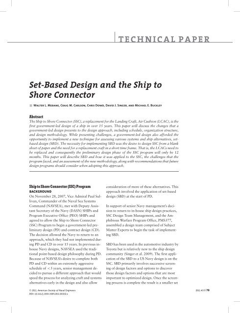
The <strong>Ship</strong> <strong>to</strong> <strong>Shore</strong> Connec<strong>to</strong>r (SSC), a replacement for <strong>the</strong> L<strong>and</strong>ing Craft, Air Cushion (LCAC), is <strong>the</strong><br />
first government-led design of a ship in over 15 years. This paper will discuss <strong>the</strong> changes that a<br />
government-led design presents <strong>to</strong> <strong>the</strong> design approach, including schedule, organization structure,<br />
<strong>and</strong> design methodology. While presenting challenges, a government-led design also afforded <strong>the</strong><br />
opportunity <strong>to</strong> implement a new technique for assessing various systems <strong>and</strong> ship alternatives, setbased<br />
design (SBD). The necessity for implementing SBD was <strong>the</strong> desire <strong>to</strong> design SSC from a blank<br />
sheet of paper <strong>and</strong> <strong>the</strong> need for a replacement craft in a short time frame. That is, <strong>the</strong> LCACs need <strong>to</strong><br />
be replaced <strong>and</strong> consequently <strong>the</strong> preliminary design phase of <strong>the</strong> SSC program will only be 12<br />
months. This paper will describe SBD <strong>and</strong> how it was applied <strong>to</strong> <strong>the</strong> SSC, <strong>the</strong> challenges that <strong>the</strong><br />
program faced, <strong>and</strong> an assessment of <strong>the</strong> new methodology, along with recommendations that future<br />
design programs should consider when adopting this approach.<br />
<strong>Ship</strong> <strong>to</strong><strong>Shore</strong> Connec<strong>to</strong>r (SSC) Program<br />
BACKGROUND<br />
On November 28, 2007, Vice Admiral Paul Sullivan,<br />
Comm<strong>and</strong>er of <strong>the</strong> Naval Sea Systems<br />
Comm<strong>and</strong> (NAVSEA), met with Deputy Assistant<br />
Secretary of <strong>the</strong> Navy (DASN) SHIPs <strong>and</strong><br />
Program Executive Office (PEO) SHIPs <strong>and</strong><br />
agreed <strong>to</strong> allow <strong>the</strong> <strong>Ship</strong> <strong>to</strong> <strong>Shore</strong> Connec<strong>to</strong>r<br />
(SSC) Program <strong>to</strong> begin a government-led preliminary<br />
design (PD) <strong>and</strong> contract design (CD).<br />
The decision allowed <strong>the</strong> Navy <strong>to</strong> return <strong>to</strong> an<br />
approach, which <strong>the</strong>y had not implemented during<br />
PD <strong>and</strong> CD in over 15 years. In previous inhouse<br />
Navy designs, NAVSEA used <strong>the</strong> traditional<br />
point-based design philosophy during PD.<br />
Because of NAVSEA’s desire <strong>to</strong> complete both<br />
PD <strong>and</strong> CD within an extremely aggressive<br />
schedule of o3 years, senior management decided<br />
<strong>to</strong> pursue a different approach that would<br />
speed <strong>the</strong> process for analyzing craft <strong>and</strong> systems<br />
alternatives early in <strong>the</strong> design <strong>and</strong> also allow<br />
& 2011, American Society of Naval Engineers<br />
DOI: 10.1111/j.1559-3584.2011.00332.x<br />
TECHNICAL PAPER<br />
consideration of more of <strong>the</strong>se alternatives. This<br />
approach involved <strong>the</strong> application of set-based<br />
design (SBD) at <strong>the</strong> start of PD.<br />
In support of senior Navy management’s decision<br />
<strong>to</strong> return <strong>to</strong> in-house ship design practices,<br />
SSC <strong>Design</strong> Team Management, <strong>and</strong> <strong>the</strong> Amphibious<br />
Warfare Program Office, PMS377,<br />
assembled a design team comprised of Subject<br />
Matter Experts <strong>to</strong> begin <strong>the</strong> task of implementing<br />
SBD.<br />
SBD has been used in <strong>the</strong> au<strong>to</strong>motive industry by<br />
Toyota but is relatively new <strong>to</strong> <strong>the</strong> ship design<br />
community (Singer et al. 2009). The first application<br />
of <strong>the</strong> SBD <strong>to</strong> a US Navy design is on <strong>the</strong><br />
SSC. SBD primarily involves successive screening<br />
of design fac<strong>to</strong>rs <strong>and</strong> options <strong>to</strong> discover<br />
those design fac<strong>to</strong>rs <strong>and</strong> options that are most<br />
important <strong>to</strong> optimized design. Once <strong>the</strong> screening<br />
process is complete <strong>the</strong> result is a smaller set<br />
2011 #3&79
<strong>Set</strong>-<strong>Based</strong> <strong>Design</strong><br />
80 & 2011 #3<br />
of potential designs, which subsequently allow<br />
designers <strong>to</strong> evaluate <strong>and</strong> analyze <strong>the</strong> remaining<br />
trade space of feasible designs in ever-increasing<br />
engineering detail until a best solution or family<br />
of solutions is developed. As <strong>the</strong> design process<br />
continues <strong>the</strong> designers may revisit decisions<br />
previously made in <strong>the</strong> trade space if requirements<br />
changes are warranted.<br />
As described by Bernstein (1998), SBD preserves<br />
design flexibility through three basic tenets:<br />
& underst<strong>and</strong> <strong>the</strong> design space,<br />
& integrate by intersection,<br />
& establish feasibility before commitment.<br />
The SSC design faced several challenges <strong>to</strong><br />
implement SBD. Most notably, a very young,<br />
inexperienced team of engineers from <strong>the</strong> Naval<br />
Warfare Centers who would be responsible for<br />
leading <strong>the</strong> system development effort. The lead<br />
systems engineers were called Systems Engineering<br />
Managers (SEMs).<br />
Toyota, <strong>the</strong> Japanese au<strong>to</strong>mobile manufacturer,<br />
had successfully implemented SBD <strong>to</strong> satisfac<strong>to</strong>rily<br />
produce au<strong>to</strong>mobile designs in less time than<br />
<strong>the</strong>ir competi<strong>to</strong>rs (Ward et al. 1995). The SSC<br />
<strong>Design</strong> Team sought <strong>the</strong> expertise of Dr. David<br />
Singer, University of Michigan, who has conducted<br />
extensive research on <strong>the</strong> use of SBD for<br />
ship design, <strong>to</strong> act as an advisor <strong>and</strong> consultant<br />
before <strong>and</strong> during <strong>the</strong> PD <strong>and</strong> CD phases of design<br />
(Singer 2003). By implementing SBD, <strong>the</strong><br />
SSC <strong>Design</strong> Team successfully designed a converged<br />
craft while meeting a dem<strong>and</strong>ing design<br />
schedule, completing <strong>the</strong> PD Phase of <strong>the</strong> SSC<br />
program within 12 months while considering a<br />
far larger number of alternatives than in a traditional<br />
point-based design evolution.<br />
GENESIS OF SSC REQUIREMENTS<br />
The SSC is <strong>the</strong> next generation Air Cushion Vehicle<br />
(ACV) that is planned as a replacement for<br />
<strong>the</strong> current fleet of L<strong>and</strong>ing Craft, Air Cushion<br />
(LCAC), which have been in service since 1984.<br />
LCAC concept design began in <strong>the</strong> 1970s <strong>and</strong><br />
resulted in full-scale Amphibious Assault L<strong>and</strong>-<br />
ing Craft test vehicles. At <strong>the</strong> conclusion of <strong>the</strong><br />
Advanced Development Stage, two pro<strong>to</strong>types<br />
were built <strong>to</strong> prove <strong>the</strong> feasibility of high-density<br />
hovercraft for <strong>the</strong> Navy. The two craft, JEFF A<br />
<strong>and</strong> JEFF B, were built by Aerojet General <strong>and</strong><br />
Bell Aerospace, respectively. The Navy eventually<br />
selected JEFF B, which subsequently became<br />
<strong>the</strong> design basis for <strong>the</strong> LCAC. From 1984<br />
through 2000, a <strong>to</strong>tal of 91 craft were delivered<br />
<strong>to</strong> <strong>the</strong> Navy. Textron Marine <strong>and</strong> L<strong>and</strong> Systems<br />
in New Orleans built 76 craft <strong>and</strong> Avondale<br />
Gulfport Marine in Gulfport, Mississippi built<br />
15 craft. The last LCAC delivered <strong>to</strong> <strong>the</strong> Navy<br />
was LCAC 91, which served as <strong>the</strong> basis for<br />
<strong>the</strong> LCAC Service Life Extension Program<br />
(SLEP) <strong>and</strong> was designed <strong>and</strong> built with <strong>the</strong><br />
LCAC SLEP improvements installed during<br />
construction.<br />
The SSC’s mission is similar <strong>to</strong> <strong>the</strong> current inservice<br />
LCAC, <strong>to</strong> transport joint forces <strong>and</strong><br />
equipment <strong>and</strong> ensure <strong>the</strong> Navy continues <strong>to</strong><br />
possess a high-speed, over-<strong>the</strong>-beach, l<strong>and</strong>ing<br />
craft in <strong>the</strong> conduct of operations launched from<br />
<strong>the</strong> sea base within Operational Maneuver from<br />
<strong>the</strong> Sea. The SSC will transport equipment, personnel,<br />
<strong>and</strong> cargo from ships located over <strong>the</strong><br />
horizon, through <strong>the</strong> surf zone, <strong>to</strong> l<strong>and</strong>ing points<br />
beyond <strong>the</strong> high water mark in a variety of environmental<br />
conditions.<br />
The current fleet of LCACs begins phasing out of<br />
service in 2015. The LCACs have been <strong>the</strong><br />
workhorse for carrying forces <strong>and</strong> supplies<br />
ashore during amphibious operations, but have<br />
become a significant consumer of operating<br />
force funds due <strong>to</strong> an increasing maintenance<br />
burden, aging technology, <strong>and</strong> obsolescence.<br />
Today <strong>the</strong>re are 79 LCACs in operation at Assault<br />
Craft Unit (ACU) 4 (Little Creek, Norfolk,<br />
VA) <strong>and</strong> ACU 5 (Camp Pendle<strong>to</strong>n, CA). The<br />
LCAC is designed <strong>to</strong> transport weapon systems,<br />
including United States Marine Corps equipment,<br />
in addition <strong>to</strong> cargo <strong>and</strong> personnel from<br />
Navy amphibious ships via <strong>the</strong> well deck <strong>to</strong> <strong>the</strong><br />
beach <strong>and</strong> beyond. LCACs were designed for a<br />
20-year service life, <strong>to</strong> carry a design payload of<br />
NAVAL ENGINEERS JOURNAL
up <strong>to</strong> 60 short <strong>to</strong>ns (i.e., an M60 tank), at 35<br />
knots, in a Sea State 3, from 15 nautical miles<br />
offshore, <strong>and</strong> are capable of operating independent<br />
of tides, water depth, underwater obstacles,<br />
ice, mud, or beach gradient. As tank designs<br />
progressed, <strong>the</strong> M60 tank was replaced with <strong>the</strong><br />
M1A1 Abrams tank, which currently weighs 72<br />
short <strong>to</strong>ns with an additional 2 short <strong>to</strong>ns for <strong>the</strong><br />
Track Width Mine Plow (TWMP). Because of<br />
naval architectural safety operating limits,<br />
LCACs require an operational waiver <strong>and</strong> must<br />
sacrifice fuel capacity <strong>and</strong> thus range in order <strong>to</strong><br />
operate in an overload condition (i.e., in order <strong>to</strong><br />
carry an M1A1 tank with TWMP). SSCs were<br />
designed for a 30-year service life, <strong>to</strong> carry a<br />
design payload of up <strong>to</strong> 74 short <strong>to</strong>ns in a<br />
nonoverload condition, at 35 knots, in a<br />
Sea State 3, from 25 nautical miles offshore, <strong>and</strong><br />
are capable of operating independent of tides,<br />
water depth, underwater obstacles, ice, mud, or<br />
beach gradient. Interoperability constraints<br />
require <strong>the</strong> SSCs <strong>to</strong> enter <strong>and</strong> exit <strong>the</strong> well decks<br />
of existing amphibious ships (e.g., LPD, LSD,<br />
<strong>and</strong> LHD).<br />
To address <strong>the</strong> concerns of aging craft, <strong>the</strong> Navy<br />
began <strong>the</strong> LCAC SLEP <strong>to</strong> add an additional 10<br />
years <strong>to</strong> <strong>the</strong> craft service life. Initially <strong>the</strong> LCAC<br />
SLEP replaced <strong>the</strong> buoyancy box (hull) of <strong>the</strong><br />
first 11 craft along with refurbished rotating<br />
machinery, upgraded <strong>the</strong> Comm<strong>and</strong>, Control,<br />
Communications, Computers, <strong>and</strong> Navigation<br />
(C4N) System, enhanced <strong>the</strong> prime mover gas<br />
turbine engines, <strong>and</strong> implemented a new<br />
skirt design, <strong>the</strong> Deep Skirt. Analysis revealed<br />
additional cost savings by refurbishing<br />
vice replacing remaining craft buoyancy<br />
boxes.<br />
The SSC Program began with studies <strong>and</strong> analysis<br />
in 2005. The Initial Capabilities Document<br />
(ICD) <strong>and</strong> Analysis of Alternatives (AoA) were<br />
approved in 2006 <strong>and</strong> 2007, respectively.<br />
NEW ACQUISITION AND DESIGN PROCESS<br />
CHALLENGES<br />
The decision <strong>to</strong> pursue a government-led design<br />
was based on several fac<strong>to</strong>rs. There were a small<br />
number of first or second tier shipyards in <strong>the</strong><br />
United States Industrial Base with ACV design<br />
expertise, so competition would likely be limited<br />
if <strong>the</strong>se yards were <strong>to</strong> develop <strong>the</strong> design. The<br />
Navy had more experience with ACV technology,<br />
in particular over 20 years of operational<br />
experience with <strong>the</strong> LCAC program <strong>and</strong> LCAC<br />
SLEP. Lastly, based on recent contract experience<br />
<strong>the</strong>re was concern on private industry’s<br />
ability <strong>to</strong> meet a very time sensitive PD <strong>and</strong> CD<br />
schedule. Meeting an award date of FY 11<br />
would mean completing <strong>and</strong> certifying <strong>the</strong> Technical<br />
Data Package (TDP) by <strong>the</strong> third-quarter of<br />
FY 10. Given this aggressive schedule <strong>the</strong> program<br />
was more likely <strong>to</strong> be successful with a<br />
government-led design. The SSC <strong>Design</strong> Team<br />
began PD in April 2008 with <strong>the</strong> goal of completing<br />
<strong>the</strong> PD Phase in 12 months. This<br />
aggressive schedule, along with additional<br />
acquisition process requirements, led <strong>the</strong> SSC<br />
<strong>Design</strong> Team <strong>to</strong> pursue a novel approach <strong>to</strong><br />
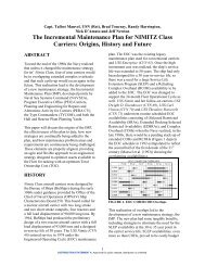
design. One of <strong>the</strong> new acquisition process requirements<br />
that challenged <strong>the</strong> program was<br />
<strong>the</strong> implementation of <strong>the</strong> new 2 Pass 6 Gate<br />
process (see Figure 1).<br />
The SSC Program had <strong>to</strong> make adjustments <strong>to</strong><br />
<strong>the</strong> new 2008 requirements since <strong>the</strong> SSC AoA<br />
had been completed in November 2007, <strong>and</strong> had<br />
been approved by <strong>the</strong> Resources, Requirement<br />
Review Board (R3B) in December 2007. The<br />
R3B subsequently was allowed <strong>to</strong> be recorded as<br />
a successful Gate 2 review.<br />
In preparation for <strong>the</strong> implementation of SBD,<br />
<strong>the</strong> SSC <strong>Design</strong> Integration Team (DIT) developed<br />
an organizational structure based on <strong>the</strong><br />
craft’s key engineering disciplines, or system<br />
engineering areas. The DIT consisted primarily<br />
of <strong>the</strong> <strong>Ship</strong> <strong>Design</strong> Manager, <strong>the</strong> Deputy <strong>Ship</strong><br />
<strong>Design</strong> Manager, <strong>and</strong> <strong>the</strong> <strong>Design</strong> Integration<br />
Manager. The <strong>Design</strong> Team was organized by<br />
systems engineering areas. These system engineering<br />
areas were each lead by a SEM <strong>and</strong><br />
included <strong>the</strong> following areas: Auxiliary, C4N,<br />
Machinery, Hull, Human System Integration,<br />
<strong>and</strong> Performance. The <strong>Design</strong> Team was augmented<br />
by naval engineers in industry, including<br />
NAVAL ENGINEERS JOURNAL 2011 #3&81
<strong>Set</strong>-<strong>Based</strong> <strong>Design</strong><br />
Figure 1: Navy 2 Pass 6 Gate Acquisition Process (Evans 1959)<br />
82 &2011 #3<br />
one of <strong>the</strong> world’s foremost ACV designers, CDI<br />
Marine—B<strong>and</strong> Lavis Division.<br />
One of <strong>the</strong> first challenges <strong>to</strong> requirements development<br />
<strong>and</strong> traceability for SSC was that only<br />
a limited number of requirements were defined<br />
at <strong>the</strong> start of SBD. To overcome this, <strong>the</strong> SSC<br />
<strong>Design</strong> Team needed <strong>to</strong> fur<strong>the</strong>r refine requirements<br />
based on st<strong>and</strong>ard practice, guidance<br />
from <strong>the</strong> Technical Warrant Holders, <strong>and</strong> insights<br />
gained from SBD analyses. All<br />
requirements needed <strong>to</strong> be documented for<br />
traceability, meaning that <strong>the</strong>y were derived<br />
from a valid source document. Requirements<br />
that did not have a valid source document were<br />
captured as tentative requirements in <strong>the</strong> requirements<br />
tracking system until such time as<br />
<strong>the</strong>y were formally validated. Upon approval by<br />
<strong>the</strong> DIT, <strong>the</strong> internal requirements documents<br />
were entered in<strong>to</strong> <strong>the</strong> requirements traceability<br />
application, <strong>the</strong> Dynamic Object Oriented<br />
Requirements System (DOORS s ).<br />
The <strong>Design</strong> Team used <strong>the</strong> ICD (approved<br />
Oc<strong>to</strong>ber 18, 2006), <strong>the</strong> AoA Final Report<br />
(approved November 28, 2007), <strong>and</strong> <strong>the</strong> R3B<br />
NAVAL ENGINEERS JOURNAL
Program<br />
CRAFT<br />
SPEC Element<br />
Subsections<br />
CRAFT<br />
SSC<br />
SDS<br />
Auxiliary<br />
FRD<br />
ICD AoA R3B<br />
C4N FRD<br />
Decision Memor<strong>and</strong>um (approved January 4,<br />
2008) as preliminary guidance <strong>to</strong> bound <strong>the</strong><br />
craft’s requirements while <strong>the</strong> Capabilities Development<br />
Document (CDD) was being<br />
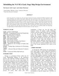
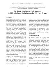
developed. As shown in Figure 2, <strong>the</strong> SSC <strong>Design</strong><br />
Team’s approach was <strong>to</strong> use <strong>the</strong> ICD, AoA, R3B,<br />
as well as <strong>the</strong> LCAC specification, <strong>and</strong> lessons<br />
learned from LCAC operations as guidance <strong>to</strong><br />
develop what <strong>the</strong> <strong>Design</strong> Team referred <strong>to</strong> as a<br />
Functional <strong>Design</strong> Document (FDD). The FDD<br />
was <strong>the</strong> set of operational requirements <strong>and</strong><br />
derived parameters used <strong>to</strong> initiate <strong>the</strong> design<br />
effort. Using <strong>the</strong> FDD as <strong>the</strong> starting point, each<br />
SEM was required <strong>to</strong> develop a Functional<br />
Requirements Document (FRD) within <strong>the</strong>ir<br />
respective area. The FRD was an evolving set of<br />
assumptions <strong>and</strong> potential requirements that<br />
fur<strong>the</strong>r defined <strong>the</strong> element trade space <strong>and</strong><br />
ultimately constrained element-specific<br />
requirements. After initial craft-level design<br />
requirements were developed <strong>and</strong> approved by<br />
<strong>the</strong> DIT, <strong>the</strong> SSC <strong>Design</strong> Team began planning<br />
HSI<br />
FRD<br />
FDD<br />
SWBS<br />
SSC<br />
SPEC<br />
Figure 2: <strong>Ship</strong> <strong>to</strong> <strong>Shore</strong> Connec<strong>to</strong>r (SSC) Requirements <strong>to</strong> Specification Evolution<br />
Hull FRD<br />
LCAC<br />
SLEP<br />
Machinery<br />
FRD<br />
Lessons<br />
Learned<br />
SSC<br />
CDD<br />
Performance<br />
FRD<br />
for PD <strong>and</strong> initiated <strong>the</strong> SBD effort. It should be<br />
noted that <strong>the</strong> requirements in <strong>the</strong> FDD<br />
<strong>and</strong> FRDs were subsequently mapped <strong>to</strong> <strong>the</strong>ir<br />
respective <strong>Ship</strong> Work Breakdown Structure<br />
(SWBS) area <strong>to</strong> become <strong>the</strong> draft specification<br />
for SSC.<br />
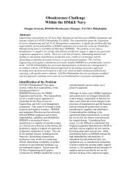
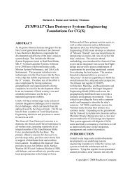
Once <strong>the</strong> SSC requirements development process<br />
was established, <strong>the</strong> SSC DIT began preparation<br />
of <strong>the</strong> SSC PD Schedule, which included SBD, as<br />
shown in Figure 3. The SBD portion occurred<br />
before PD <strong>and</strong> was also referred <strong>to</strong> as prepreliminary<br />
design. Upon completion of trade<br />
studies associated with SBD, <strong>the</strong> DIT spent approximately<br />
6 weeks integrating <strong>the</strong> various<br />
systems in<strong>to</strong> <strong>the</strong> proposed baseline. This baseline<br />
was briefed <strong>to</strong> senior NAVSEA Technical representatives<br />
for concurrence <strong>and</strong> carried forward<br />
in<strong>to</strong> PD.<br />
PD incorporated two PD iterations (PD-1<br />
<strong>and</strong> PD-2) <strong>and</strong> a period in which changes<br />
Considerations<br />
Program<br />
Office<br />
TWH<br />
Stakeholders/<br />
Draft SSC<br />
CDD<br />
NAVAL ENGINEERS JOURNAL 2011 #3&83
<strong>Set</strong>-<strong>Based</strong> <strong>Design</strong><br />
Month<br />
Proposed<br />
Integration<br />
Baseline<br />
Subsystem Trade Studies Period PD-1 PD-2 Review<br />
Review<br />
Apr 21 Jun 21 Aug 18 Sep 26 Nov 3 Dec 19 Jan 5<br />
Feb 20 Mar 26 May 1<br />
<strong>Design</strong> Space<br />
Brief<br />
<strong>Set</strong>-<strong>Based</strong> <strong>Design</strong><br />
Trade<br />
Space<br />
Parameters<br />
Proposed<br />
Baseline<br />
resulting from model <strong>and</strong> analytical testing<br />
initiated during SBD could be incorporated.<br />
The PD-1 <strong>and</strong> PD-2 design phases were iterative<br />
developments lasting approximately 2 months<br />
each. The resulting baseline was briefed <strong>to</strong> senior<br />
NAVSEA Technical representatives for concurrence<br />
<strong>and</strong> carried forward in<strong>to</strong> CD.<br />
The resulting product at <strong>the</strong> end of PD <strong>and</strong> CD<br />
was a SSC TDP that consisted of a 112 section<br />
craft specification of over 700 pages, 32 contract<br />
drawings, <strong>and</strong> 6 Project Peculiar Documents.<br />
The craft specification was organized <strong>and</strong><br />
assembled consistent with SWBS. Each specification<br />
section was approved <strong>and</strong> signed by its<br />
representative Technical Warrant Holder, <strong>and</strong><br />
<strong>the</strong>ir respective senior management, or Deputy<br />
Warranting Officer.<br />
Point<br />
<strong>Design</strong><br />
Output<br />
Functional<br />
Baseline<br />
CD Prep<br />
0 1 2 3 4 5 6 7 8 9 10 11 12<br />
Figure 3: <strong>Ship</strong> <strong>to</strong> <strong>Shore</strong> Connec<strong>to</strong>r (SSC) Preliminary <strong>Design</strong> Schedule<br />
84 &2011 #3<br />
Preliminary <strong>Design</strong> Phase<br />
Point<br />
<strong>Design</strong><br />
Output<br />
SBD AS APPLIED TO SSC<br />
Before <strong>the</strong> SSC design, all o<strong>the</strong>r navy ship designs<br />
have used <strong>the</strong> classic <strong>Design</strong> Spiral<br />
approach, as shown in Figure 4. Under this<br />
method, all design activities are accomplished in<br />
a particular order. Once each design cycle is<br />
complete, it is tested for design convergence<br />
<strong>and</strong> if not met, ano<strong>the</strong>r cycle is repeated at a<br />
higher level of fidelity. Once convergence is<br />
achieved <strong>the</strong> design is fur<strong>the</strong>r developed <strong>and</strong><br />
refined.<br />
In applying <strong>the</strong> SBD process <strong>to</strong> <strong>the</strong> SSC, <strong>the</strong><br />
SEMs communicated ranges of solutions with<br />
associated derived requirements for various<br />
systems <strong>and</strong> performance levels ra<strong>the</strong>r than<br />
develop a single point solution. Figure 5 depicts<br />
how intersecting different ranges of solutions<br />
NAVAL ENGINEERS JOURNAL
Figure 4: Classic <strong>Design</strong> Spiral<br />
from different system engineering areas<br />
determined regions of feasibility. Examples of<br />
<strong>the</strong>se regions include speed, length, or beam<br />
of <strong>the</strong> craft.<br />
SBD execution was facilitated by <strong>the</strong> DIT staff.<br />
SEMs led <strong>the</strong>ir respective teams, continuously<br />
interfaced with each of <strong>the</strong> o<strong>the</strong>r SEMs, <strong>and</strong><br />
reported <strong>to</strong> <strong>the</strong> DIT. Periodically, SEMs were<br />
tasked <strong>to</strong> filter out inferior or infeasible options<br />
in <strong>the</strong>ir respective design areas based on <strong>the</strong>ir<br />
team’s design experience. The filtering was<br />
managed in a way that limited <strong>the</strong> risk of<br />
eliminating promising <strong>and</strong> feasible design options.<br />
In assessing which approach would allow <strong>the</strong><br />
SSC design <strong>to</strong> converge, <strong>the</strong> DIT decided not <strong>to</strong><br />
pursue continuous function regression analysis<br />
NAVAL ENGINEERS JOURNAL 2011 #3&85
<strong>Set</strong>-<strong>Based</strong> <strong>Design</strong><br />
Figure 5: <strong>Set</strong>-<strong>Based</strong><br />
<strong>Design</strong> (Bernstein<br />
1998)<br />
(1)<br />
Specialty A<br />
(2)<br />
Intersection of Independent<br />
Solutions<br />
(3)<br />
(4)<br />
(5)<br />
Specialty B<br />
Specialty C<br />
techniques at <strong>the</strong> craft level because <strong>the</strong> trade<br />
space was a complex mix of discrete choices<br />
<strong>and</strong> continuous ranges, making <strong>the</strong> approach<br />
intractable for <strong>the</strong> global screening within<br />
schedule constraints.<br />
Figure 6: <strong>Set</strong>-<strong>Based</strong> <strong>Design</strong> Process Diagram with Numbered Processes<br />
86 & 2011 #3<br />
The SSC <strong>Design</strong> Team developed <strong>the</strong>ir schedule<br />
implementing SBD by dividing <strong>the</strong> process in<strong>to</strong><br />
three distinct steps—Trade Space <strong>Set</strong>up <strong>and</strong><br />
Characterization, Trade Space Reduction, <strong>and</strong><br />
Integration <strong>and</strong> Scoring (see Figure 6).<br />
The first step in <strong>the</strong> SBD process for <strong>the</strong> SSC<br />
<strong>Design</strong> Team was Trade Space <strong>Set</strong>up <strong>and</strong> Characterization.<br />
This subsequently led <strong>to</strong> <strong>the</strong><br />
development of Trade Space Summaries (TSSs).<br />
The TSSs were developed <strong>to</strong> include all that<br />
information required <strong>to</strong> characterize <strong>the</strong> element<br />
trade spaces, see Blocks (3), (4), (5), <strong>and</strong> (6) in<br />
Figure 6. Included in Trade Space <strong>Set</strong>up <strong>and</strong><br />
Characterization was <strong>the</strong> incorporation of operational<br />
requirements, element specific attributes,<br />
<strong>and</strong> impacts resulting from interactions with<br />
Technical Warrant Holders, Block (9) in Figure 6.<br />
The TSSs served several functions: (1) Define/<br />
Describe each element’s trade space on a separate<br />
worksheet in <strong>the</strong> workbook; (2) Track progress in<br />
reducing each element’s trade space; (3) Track<br />
progress in determining which craft-level<br />
NAVAL ENGINEERS JOURNAL
attributes would contribute <strong>to</strong> <strong>the</strong> valuation of<br />
alternative craft designs; <strong>and</strong> (4) St<strong>and</strong>ardize<br />
trade space descriptions across all elements.<br />
The TSSs were used by <strong>the</strong> DIT <strong>to</strong> track progress<br />
during trade space reduction, <strong>and</strong> <strong>to</strong> assist in<br />
reviewing, tuning, <strong>and</strong> approving trade study<br />
plans, Blocks (7) <strong>and</strong> (8) in Figure 6. The<br />
objective of <strong>the</strong> TSSs was <strong>to</strong> provide a summary<br />
of all potential design parameters <strong>and</strong> ranges of<br />
<strong>the</strong> trade study <strong>and</strong> track <strong>the</strong>m as element-specific<br />
summaries of <strong>the</strong> design parameters <strong>and</strong><br />
<strong>the</strong>ir attributes during <strong>the</strong> set reductions. Each<br />
SEM developed a TSS for his systems that captured<br />
<strong>the</strong> essential parameters <strong>to</strong> properly<br />
investigate design options from <strong>the</strong> element’s<br />
perspective. Once complete, <strong>the</strong> TSSs reflected a<br />
thorough review of each design parameter <strong>and</strong> a<br />
determination of potential significance at <strong>the</strong><br />
craft level. In addition, all <strong>the</strong> parameter ranges<br />
of study <strong>and</strong> c<strong>and</strong>idate options were identified.<br />
Throughout <strong>the</strong> Trade Space reduction, a constant<br />
discussion among <strong>the</strong> SEMs about <strong>the</strong>ir<br />
trade spaces was facilitated by <strong>the</strong> DIT.<br />
TSSs were used <strong>to</strong> assist <strong>the</strong> SEMs <strong>and</strong> DIT <strong>to</strong><br />
ensure that <strong>the</strong> output of <strong>the</strong> SEMs’ regression<br />
analyses could support a robust evaluation of<br />
integrated designs.<br />
The Trade Spaces were described by design parameters<br />
or fac<strong>to</strong>rs, options or ranges of options<br />
(independent variables), <strong>and</strong> response variables<br />
(RVs). The RVs (dependent variables) represented<br />
attributes that registered value at <strong>the</strong> craft level.<br />
Using <strong>the</strong> gearbox as an example, <strong>the</strong> Machinery<br />
SEM developed a TSS, which described <strong>the</strong><br />
gearboxes as a design parameter or independent<br />
variable. For this parameter, under specific options<br />
or variable ranges of study, <strong>the</strong> SEM listed<br />
c<strong>and</strong>idate numbers of gearboxes assessed in <strong>the</strong><br />
trade studies that included propulsion drive<br />
trains with 2, 4, 6, 8, <strong>and</strong> 10 gearboxes. The<br />
Machinery SEM applied this approach <strong>to</strong> a host<br />
of design parameters, including: types of lift<br />
fans, c<strong>and</strong>idate propulsors, bow thrusters, prime<br />
mover options, main engine type, quantities, <strong>and</strong><br />
orientations. All SEMs applied this approach <strong>to</strong><br />
<strong>the</strong>ir design parameters. The Auxiliaries SEM’s<br />
design parameters included Fire Suppression<br />
Systems, HVAC Systems, Fuel Pumps, <strong>and</strong> Control<br />
Actua<strong>to</strong>rs.<br />
The ‘‘RVs’’ for <strong>the</strong> design parameter ‘‘gearboxes’’<br />
included Weight, Reliability, Cost, <strong>and</strong> Footprint.<br />
For <strong>the</strong> design parameter ‘‘Main Engine<br />
Quantity,’’ RVs included Costs, Reliability,<br />
Availability, Excess Power, Footprint, Height,<br />
<strong>and</strong> Weight.<br />
The second step in <strong>the</strong> SBD process as it applied<br />
<strong>to</strong> <strong>the</strong> SSC Program was Element Trade Space<br />
Analysis <strong>and</strong> Reduction (see Figure 6). Once <strong>the</strong><br />
risks, traceability <strong>to</strong> requirements documents<br />
<strong>and</strong> trade space boundary criteria were developed,<br />
<strong>the</strong> <strong>Design</strong> Team examined multiple<br />
alternatives within each SEM area <strong>to</strong> arrive at<br />
acceptable intersections of feasible sets. The <strong>Design</strong><br />
Team also identified a number of concepts<br />
that spanned a range of attributes (potential requirements).<br />
To seek convergence in <strong>the</strong> range of<br />
designs, each SEM conducted key trade studies<br />
that eventually led <strong>to</strong> <strong>the</strong> selection <strong>and</strong> location<br />
of major equipment <strong>and</strong> functions.<br />
The SBD process as implemented included a systematic<br />
bounding of <strong>the</strong> trade space, developing<br />
measures of effectiveness, paring down alternatives,<br />
performing <strong>the</strong> analysis needed <strong>to</strong> identify<br />
feasible, <strong>and</strong> nondominated system <strong>and</strong> component<br />
alternatives. The key <strong>to</strong>ols used while<br />
executing SBD included a wide range of analysis<br />
<strong>and</strong> data management <strong>to</strong>ols. In many cases, <strong>the</strong><br />
<strong>to</strong>ols were specific <strong>to</strong> <strong>the</strong> subsystem analysis being<br />
performed as well as <strong>the</strong> analyst performing<br />
<strong>the</strong> work.<br />
Several SEMs used statistical analysis software<br />
<strong>to</strong>ols in <strong>Design</strong> of Experiments (DOE). DOE is a<br />
statistics-based procedure that implements a<br />
number of simulation runs <strong>and</strong> tests <strong>to</strong> characterize<br />
system/component performance under a<br />
wide variety of conditions. The SEMs exported<br />
<strong>the</strong> data <strong>to</strong> plot <strong>and</strong> generate response surfaces<br />
<strong>to</strong> fur<strong>the</strong>r investigate areas of <strong>the</strong> design space.<br />
NAVAL ENGINEERS JOURNAL 2011 #3&87
<strong>Set</strong>-<strong>Based</strong> <strong>Design</strong><br />
88 & 2011 #3<br />
They <strong>the</strong>n used Pugh (1991) matrices during<br />
early exploration of <strong>the</strong> trade space <strong>to</strong> provide a<br />
means <strong>to</strong> compare several design concepts<br />
against an established datum. This approach allowed<br />
<strong>the</strong> SEMs <strong>to</strong> quickly <strong>and</strong> easily identify<br />
<strong>the</strong> most feasible alternatives.<br />
In developing a SBD baseline design, <strong>the</strong> DIT<br />
assisted <strong>the</strong> SEMs in reducing <strong>the</strong>ir fields of<br />
element options by screening remaining design<br />
combinations, in search of nondominated solutions<br />
at <strong>the</strong> craft level. As <strong>the</strong> SEMs reduced <strong>the</strong>ir<br />
design space, <strong>the</strong>y began concentrating <strong>the</strong>ir<br />
efforts on cost <strong>and</strong> risk impacts <strong>to</strong> <strong>the</strong> overall<br />
program. Their focus was on arriving at Pare<strong>to</strong><br />
dominated solutions, which are solutions with<br />
superior performance at lower cost, which were<br />
carried forward. This concluded with a design,<br />
which valued in performance, cost, <strong>and</strong> risk.<br />
Screening rules allowed <strong>the</strong> SEMs <strong>to</strong> reduce <strong>the</strong><br />
trade space based on: design parameter significance,<br />
comparison of discrete options within a<br />
given design parameter, <strong>and</strong> identification of<br />
dominated solutions based on specific options or<br />
ranges of options within a design parameter.<br />
SEMs were allowed <strong>to</strong> relax <strong>the</strong> assigned performance<br />
<strong>and</strong> weight attribute ranges for <strong>the</strong>ir<br />
respective element based on <strong>the</strong>ir knowledge of<br />
available components, technologies, materials,<br />
<strong>and</strong> o<strong>the</strong>r fac<strong>to</strong>rs that could offer benefit <strong>to</strong> <strong>the</strong><br />
craft as a whole. This was done <strong>to</strong> avoid overconstraining<br />
<strong>the</strong> explored design space <strong>and</strong> missing<br />
potentially promising design solutions. The<br />
SEMs <strong>the</strong>n converted <strong>the</strong> relaxed performance<br />
<strong>and</strong> weight craft-level attribute ranges in<strong>to</strong> sets of<br />
options, subsystem <strong>and</strong> component sets, <strong>and</strong><br />
subsystem attributes <strong>and</strong> attribute ranges that<br />
defined <strong>the</strong> extent of each element’s trade space.<br />
Afterwards, <strong>the</strong> SEMs conducted trade studies <strong>to</strong><br />
develop <strong>and</strong> comparatively evaluate subsystem<br />
alternatives within <strong>the</strong>ir trade space <strong>and</strong> subsequently<br />
developed criteria <strong>to</strong> support <strong>the</strong><br />
comparative evaluation of <strong>the</strong> subsystem alternatives.<br />
They also screened infeasible or<br />
dominated trade space options <strong>and</strong> developed a<br />
set of nondominated attribute ranges with <strong>the</strong><br />
DIT providing oversight. The trade space reduction<br />
efforts on <strong>the</strong> SSC can be described as two<br />
subefforts: (1) Fac<strong>to</strong>r/Option Screening <strong>and</strong> (2)<br />
Combination Screening. The Fac<strong>to</strong>r/Option<br />
Screening effort focused on screening whole design<br />
parameters <strong>and</strong> options or option sets, while<br />
<strong>the</strong> Combination Screening effort focused on<br />
screening specific combinations of options based<br />
on incompatibilities.<br />
For comparative evaluation, ‘‘pseudo designs,’’<br />
or integrated, craft-level concepts were developed.<br />
They were called pseudo designs because<br />
<strong>the</strong>y had yet <strong>to</strong> be tested for craft-level viability<br />
based on some simple, craft-level checks.<br />
These c<strong>and</strong>idate configurations were <strong>the</strong>n subjected<br />
<strong>to</strong> a Balance Loop check <strong>to</strong> ensure that <strong>the</strong><br />
design c<strong>and</strong>idates passed a first order test for<br />
craft viability.<br />
The third <strong>and</strong> final segment of <strong>the</strong> SSC SBD<br />
effort was Integration <strong>and</strong> Scoring. The DIT was<br />
unsure which method would provide <strong>the</strong> program<br />
with <strong>the</strong> most effective (<strong>and</strong> timely)<br />
convergence result. At this point <strong>the</strong> trade space<br />
numbered approximately 10 8 potential design<br />
options. The DIT was faced with deciding<br />
among four convergence options.<br />
These options included: (1) a brute force method<br />
where specific infeasibilities were diligently<br />
sought, (2) <strong>the</strong> use of a design syn<strong>the</strong>sis model,<br />
(3) a fac<strong>to</strong>r screening method based on multiple<br />
linear regression techniques, <strong>and</strong> (4) a method<br />
enlisting negotiating functions defining interactions<br />
among <strong>the</strong> design parameters. The DIT<br />
subsequently used a brute force method.<br />
BALANCE LOOP<br />
In trimming <strong>the</strong> trade space during <strong>the</strong> final step<br />
(Integration <strong>and</strong> Scoring), <strong>the</strong> number of combinations<br />
(largely driven by <strong>the</strong> remaining<br />
machinery [432] <strong>and</strong> hull [90] options) remaining<br />
after <strong>the</strong> screening of known dominated<br />
solutions approached 40,000 combinations.<br />
This was reduced <strong>to</strong> 10,368 when certain hull<br />
configurations were eliminated from fur<strong>the</strong>r<br />
consideration due <strong>to</strong> cost <strong>and</strong> weight. However,<br />
NAVAL ENGINEERS JOURNAL
Define<br />
Operational<br />
Envelope<br />
Pass Criteria<br />
Identify<br />
“Feasible”<br />
C<strong>and</strong>idate<br />
Machinery,<br />
Hull, & Skirt<br />
Options<br />
Define <strong>Design</strong><br />
Combinations<br />
for Test<br />
<strong>Design</strong><br />
Test Loop<br />
Max Intermittent Power(MIP) adequate for Hump<br />
Max Continuous Power (MCP) adequate for Cruise<br />
Stability Check<br />
Weight convergence(in 50 trials)<br />
Perform Stability<br />
Check<br />
Check Craft<br />
Dimensions<br />
Tally Weights (including Fuel) &<br />
Costs Across All Elements<br />
Calculate Loads<br />
(SWBS F10, F20, F42 & F62)<br />
<strong>the</strong> remaining 10,368 combinations needed <strong>to</strong> be<br />
evaluated for feasibility as physically viable<br />
craft. Looking at <strong>the</strong> combinations as potential<br />
craft design solutions, <strong>the</strong> DIT next used a useful<br />
<strong>and</strong> necessary first-order craft-level feasibility<br />
check. This <strong>to</strong>ol was referred <strong>to</strong> as <strong>the</strong> Balance<br />
Loop (see Figure 7).<br />
The <strong>Design</strong> Team used <strong>the</strong> Balance Loop <strong>to</strong><br />
screen trade space combinations based on a<br />
first-order check for physical viability as an operating<br />
hovercraft. The Balance Loop included<br />
an initial stability check, a test for adequate<br />
power for <strong>the</strong> craft <strong>to</strong> get over hump, <strong>and</strong> a<br />
check for <strong>the</strong> craft’s ability <strong>to</strong> maintain <strong>the</strong> required<br />
cruise speed. As a result of <strong>the</strong> Balance<br />
Loop check, <strong>the</strong> initial 10,368 options were reduced<br />
<strong>to</strong> 3,397 viable solutions for scoring. The<br />
Balance Loop operation identified viable Skirt,<br />
Machinery, Hull, <strong>and</strong> Auxiliaries combinations<br />
<strong>and</strong> tallied costs <strong>and</strong> weights, resulting in a converged<br />
fully loaded craft weight. The Balance<br />
Loop was successful in ensuring that (1) <strong>the</strong> major<br />
components of each design were balanced for<br />
weight <strong>and</strong> power; (2) <strong>the</strong> craft met a power-at-<br />
For Given<br />
Combination,<br />
Estimate Full<br />
Load Weight<br />
based on<br />
Payload<br />
Revise Full<br />
Load Weight<br />
Estimate<br />
Weight<br />
Loop<br />
Make Allowance for Outfitting &<br />
Furnishings: Weights, & Costs<br />
(SWBS 600)<br />
Retrieve Geometry,<br />
Weight <strong>and</strong> Cost for<br />
assigned Skirt<br />
(SWBS 119)<br />
Calculate Cushion<br />
Pressure & Flow<br />
Calculate Craft<br />
Resistance <strong>Based</strong><br />
on Skirt<br />
Retrieve Machinery Cost<br />
Weight <strong>and</strong> Performance<br />
Data; Check for Viability<br />
(SWBS 200,300,& 500)<br />
Retrieve Hull, Cost, Weight,<br />
<strong>and</strong> Performance Data; Check<br />
for Viability (SWBS 100)<br />
Retrieve C4N Loads,<br />
Weights, & Costs<br />
(SWBS 400)<br />
hump threshold; (3) fuel needs were accommodated;<br />
(4) <strong>the</strong> costs were tallied; <strong>and</strong> (5) <strong>the</strong> craft<br />
passed an empirical dynamic stability check.<br />
After completion of <strong>the</strong> Balance Loop check, <strong>the</strong><br />
results were verified through a five-step process<br />
that included: (1) verification of machinery<br />
architecture selection, (2) verification of hull<br />
architecture selection, (3) verification of variable<br />
assignment within Visual Basic code, (4)<br />
verification of cell assignments within worksheets,<br />
<strong>and</strong> (5) h<strong>and</strong> verification of <strong>the</strong> Balance<br />
Loop process.<br />
The remaining 3,397 configurations were <strong>the</strong>n<br />
comparatively evaluated in <strong>the</strong> measures considered<br />
most important for craft value. For this<br />
effort <strong>the</strong> DIT used a <strong>to</strong>ol known as Logical<br />
Decision (LD) <strong>to</strong> score <strong>the</strong> remaining c<strong>and</strong>idate<br />
configurations. LDs are commercially available<br />
decision analysis software. LD is founded on<br />
multiattribute utility principles. The LD Scoring<br />
Model was developed concurrently with <strong>the</strong><br />
Balance Loop Software <strong>and</strong> built on <strong>the</strong><br />
evolutionary effort begun at <strong>the</strong> beginning of<br />
Figure 7: Diagram of <strong>the</strong> Balance Loop<br />
Process<br />
NAVAL ENGINEERS JOURNAL 2011 #3&89
<strong>Set</strong>-<strong>Based</strong> <strong>Design</strong><br />
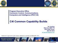
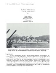
Figure 8: Trade Space Reduction Over<br />
Time<br />
90 & 2011 #3<br />
C<strong>and</strong>idate Vital <strong>Design</strong> Parameters<br />
140<br />
120<br />
100<br />
80<br />
60<br />
40<br />
20<br />
SBD <strong>to</strong> develop a sufficiently robust set of<br />
measures for craft-level scoring.<br />
0<br />
C<strong>and</strong>idate combinations remaining after <strong>the</strong><br />
Balance Loop check were entered in<strong>to</strong> an LD<br />
application specifically constructed using <strong>the</strong><br />
RVs evolved during <strong>the</strong> SBD implementation. It<br />
was called <strong>the</strong> SSC LD Evaluation Model. The<br />
Balance Loop <strong>and</strong> SSC LD Evaluation Model<br />
were developed <strong>and</strong> verified concurrently, <strong>and</strong><br />
results from <strong>the</strong> Balance Loop were fed in<strong>to</strong> <strong>the</strong><br />
LD Model in several passes. These iterations<br />
were necessary <strong>to</strong> work out data errors <strong>and</strong><br />
anomalies. When <strong>the</strong> errors in <strong>the</strong> data stream<br />
settled out, <strong>the</strong> Balance Loop tallied 3,397<br />
designs that passed <strong>the</strong> pass/fail criteria for viability.<br />
The 3,397 combinations were <strong>the</strong>n<br />
compared in <strong>the</strong> LD Model. It is important <strong>to</strong><br />
note that <strong>the</strong> Balance Loop was used at <strong>the</strong> end<br />
of <strong>the</strong> SBD process as a technical check for<br />
design feasibility. The Baseline itself did not<br />
drive <strong>the</strong> SBD process.<br />
A <strong>to</strong>tal of 11 design parameters were used in <strong>the</strong><br />
final comparison for craft-level value. These<br />
were <strong>the</strong> 11 design parameters used <strong>to</strong> differentiate<br />
<strong>the</strong> remaining c<strong>and</strong>idate configurations.<br />
That is, <strong>the</strong> o<strong>the</strong>r design parameters did not impact<br />
<strong>the</strong> craft-level value such that <strong>the</strong> parameter<br />
would impact <strong>the</strong> craft-level configuration.<br />
Trade Space Reduction<br />
(Progress from 05/07/08 <strong>to</strong> PD 1)<br />
Vital Parameters # of options (Log 10)<br />
TRADE SPACE REDUCTIONS<br />
Figure 8 depicts <strong>the</strong> rate of <strong>the</strong> trade space reduction<br />
over time, beginning early in May 2008.<br />
At that point, all SEMs had defined <strong>the</strong>ir trade<br />
spaces <strong>and</strong> it marked <strong>the</strong> formal start of <strong>the</strong><br />
reduction effort.<br />
Figure 8 looks across <strong>the</strong> trade space reduction<br />
effort, spanning all of <strong>the</strong> elements. At <strong>the</strong> start<br />
of <strong>the</strong> effort, we had over 120 design parameters<br />
<strong>and</strong> better than 10 47 design combinations. At <strong>the</strong><br />
beginning of <strong>the</strong> Integration on August 18, <strong>the</strong><br />
lion’s share of <strong>the</strong> reductions had occurred.<br />
However, at this point, <strong>the</strong>re were still 10 8<br />
design combinations remaining. The DIT moved<br />
from focusing on design fac<strong>to</strong>r <strong>and</strong> option feasibility<br />
screening <strong>to</strong> screening infeasible or<br />
dominated combinations. Discarding <strong>the</strong> dominated<br />
solutions brought <strong>the</strong> tally <strong>to</strong> a little<br />
better than 10 4 design combinations remaining.<br />
Then, <strong>the</strong> Balance Loop filter brought <strong>the</strong><br />
tally <strong>to</strong> o3,400. Comparative evaluation with<br />
<strong>the</strong> LD Model confirmed <strong>the</strong> vital fac<strong>to</strong>rs <strong>and</strong><br />
options.<br />
Using <strong>the</strong> results of LD scoring, tempered with<br />
subject matter expertise <strong>and</strong> judgment, two final<br />
configurations (one Aluminum Alloy craft <strong>and</strong><br />
one Composite craft) were selected as Baselines<br />
for <strong>the</strong> SSC.<br />
50<br />
40<br />
30<br />
20<br />
10<br />
0<br />
Option Count (Log10)<br />
NAVAL ENGINEERS JOURNAL
CONCLUSIONS<br />
The new acquisition <strong>and</strong> design process used on<br />
<strong>the</strong> SSC provided some unique insight in<strong>to</strong> <strong>the</strong><br />
challenges facing Navy Acquisition programs<br />
<strong>to</strong>day. The first being requirements definition.<br />
Like most programs, early in <strong>the</strong> design timeline,<br />
requirements are generally broad <strong>and</strong> defined at<br />
a fairly high level. This causes problems for <strong>the</strong><br />
systems engineers <strong>and</strong> designers because it is<br />
hard <strong>to</strong> develop <strong>and</strong> evaluate designs against a<br />
vague set of requirements. As an example, only<br />
<strong>the</strong> ICD was available at <strong>the</strong> start of PD, <strong>and</strong> it<br />
had only major craft-level requirements. An<br />
early version of <strong>the</strong> CDD was not available until<br />
<strong>the</strong> end of PD.<br />
The SSC program’s requirements development<br />
process allowed <strong>the</strong> systems engineer <strong>to</strong> define<br />
some of <strong>the</strong>se detail requirements early, carry<br />
<strong>the</strong>m as potential requirements until validated<br />
later by <strong>the</strong> CDD. This allowed <strong>the</strong> SBD process<br />
<strong>to</strong> go forward <strong>and</strong> permitted evaluation of an<br />
entire range of systems <strong>and</strong> craft alternatives in<br />
an orderly, structured manner. SBD offered <strong>the</strong><br />
Navy an opportunity <strong>to</strong> examine a far greater<br />
range of options <strong>and</strong> alternatives than would<br />
have been considered in traditional point-based<br />
design evolutions <strong>and</strong> allowed this <strong>to</strong> be done in<br />
a much shorter time period. One shortcoming in<br />
<strong>the</strong> process was that cost estimates for many of<br />
<strong>the</strong> systems or craft alternatives could not be<br />
made because <strong>to</strong>ols for assessing cost at this<br />
early stage are not available <strong>and</strong> only subjective<br />
reasoning could be used <strong>to</strong> assess this extremely<br />
important variable. The ability of <strong>the</strong> government<br />
engineers <strong>to</strong> once again develop designs in<br />
house was proven. The Navy’s ability <strong>to</strong> develop<br />
a design with a distributed design team with<br />
much of <strong>the</strong> design team personnel remotely located<br />
in <strong>the</strong> field was certainly proven. The<br />
ability of competent but relatively inexperienced<br />
personnel <strong>to</strong> be trained quickly <strong>to</strong> develop effective<br />
designs is not only doable but offers hope<br />
that some of <strong>the</strong> SSC practices can be adapted <strong>to</strong><br />
o<strong>the</strong>r ship design programs. It shows that despite<br />
<strong>the</strong> current staffing levels for engineers in<br />
NAVSEA, a core of experienced design engineers<br />
can be developed in <strong>the</strong> years ahead.<br />
The SBD methodology offers great potential <strong>to</strong><br />
naval ship design. The number of alternatives<br />
considered was impressive. The SSC, being an<br />
ACV, had some difficulty assessing design alternatives<br />
because <strong>the</strong> <strong>to</strong>ols available were<br />
developed <strong>to</strong> assess ship concepts <strong>and</strong> system<br />
alternatives <strong>and</strong> is somewhat limited for assessing<br />
ACVs. For surface combatant or auxiliary<br />
ships, where <strong>the</strong>re are more accredited syn<strong>the</strong>sis<br />
<strong>to</strong>ols, such as ASSET, evaluation of alternatives<br />
should be faster <strong>and</strong> easier. As <strong>the</strong> SBD<br />
methodology is exp<strong>and</strong>ed <strong>to</strong> o<strong>the</strong>r programs, a<br />
more uniform process for screening <strong>and</strong><br />
paring down alternatives should be developed <strong>to</strong><br />
accelerate evaluation <strong>and</strong> selection of <strong>the</strong> best<br />
systems for a particular mission.<br />
References<br />
Bernstein, J.I., ‘‘<strong>Design</strong> methods in <strong>the</strong> aerospace industry:<br />
looking for evidence of set-based practices.’’<br />
Master of Science <strong>the</strong>sis, Massachusetts Institute of<br />
Technology, 1998.<br />
Evans, J.H., ‘‘Basic design concepts,’’ Naval Engineers<br />
Journal, Vol. 21, pp. 671–678, November 1959.<br />
Pugh, S., Total design: integrated methods for successful<br />
product development, Addison-Wesley, Wokingham,<br />
UK, 1991.<br />
Secretary of <strong>the</strong> Navy (SECNAV), ‘‘Department of <strong>the</strong><br />
Navy (DON) Requirements <strong>and</strong> Acquisition Process<br />
Improvement.’’ SECNAVNOTE 5000 of February 26,<br />
2008.<br />
Secretary of <strong>the</strong> Navy (SECNAV), ‘‘Implementation <strong>and</strong><br />
Operation of <strong>the</strong> Defense Acquisition System <strong>and</strong> <strong>the</strong><br />
Joint Capabilities Integration <strong>and</strong> Development System.’’<br />
SECNAVINST 5000.2D of Oc<strong>to</strong>ber 16, 2008.<br />
Singer, D.J., ‘‘A hybrid agent approach for set-based<br />
conceptual ship design through <strong>the</strong> use of a fuzzy logic<br />
agent <strong>to</strong> facilitate communications <strong>and</strong> negotiation.’’<br />
Ph.D. dissertation, University of Michigan, 2003.<br />
Singer, D.J., N. Doerry, <strong>and</strong> M.E. Buckley, ‘‘What Is <strong>Set</strong>-<br />
<strong>Based</strong> <strong>Design</strong>?’’ Naval Engineers Journal, Vol. 121, No. 4,<br />
pp. 31–43, 2009.<br />
Ward, A., J.K. Liker, J.J. Christiano, <strong>and</strong> D. Sobek II.,<br />
‘‘The second Toyota paradox: how delaying decisions<br />
can make better cars faster,’’ Sloan Management<br />
Review, US, Vol. 36, pp. 43–61, 1995.<br />
NAVAL ENGINEERS JOURNAL 2011 #3&91
<strong>Set</strong>-<strong>Based</strong> <strong>Design</strong><br />
92 &2011 #3<br />
AuthorBiographies<br />
Walter L. Mebane is a <strong>Ship</strong> <strong>Design</strong> Manager<br />
(SDM) in <strong>the</strong> Future Concepts <strong>and</strong> Surface <strong>Ship</strong><br />
<strong>Design</strong> Direc<strong>to</strong>rate at <strong>the</strong> Naval Sea Systems<br />
Comm<strong>and</strong> (NAVSEA) in Washing<strong>to</strong>n, DC. He is<br />
currently <strong>the</strong> SDM for <strong>the</strong> SSC Program. He has<br />
over 27 years of experience in ship design, systems<br />
engineering, <strong>and</strong> mechanical engineering<br />
on US Navy Combatant programs. Mr. Mebane<br />
was a 2010 recipient of <strong>the</strong> coveted Secretary of<br />
<strong>the</strong> Navy Safety Integration Acquisition Award.<br />
He is one of 160 Technical Warrant Holders<br />
(TWHs) within <strong>the</strong> NAVSEA Technical Authority<br />
chain of comm<strong>and</strong> <strong>and</strong> has been <strong>the</strong> TWH for<br />
Air Cushion Vehicles for <strong>the</strong> past 8 years. His<br />
educational background includes a Master of<br />
Engineering Management degree from The<br />
George Washing<strong>to</strong>n University (GWU) <strong>and</strong> undergraduate<br />
degrees from Hamp<strong>to</strong>n University<br />
<strong>and</strong> The George Washing<strong>to</strong>n University (B.S./<br />
B.S.M.E). His professional affiliations include<br />
<strong>the</strong> American Society of Naval Engineers <strong>and</strong> <strong>the</strong><br />
American Society of Mechanical Engineers.<br />
Craig M. Carlson is <strong>the</strong> <strong>Ship</strong> <strong>to</strong> <strong>Shore</strong> Connec<strong>to</strong>r<br />
Deputy <strong>Ship</strong> <strong>Design</strong> Manager in <strong>the</strong> Future Concepts<br />
<strong>and</strong> Surface <strong>Ship</strong> <strong>Design</strong> Direc<strong>to</strong>rate at <strong>the</strong><br />
Naval Sea Systems Comm<strong>and</strong> (NAVSEA) in<br />
Washing<strong>to</strong>n, DC. Previously, he was <strong>the</strong> <strong>Ship</strong><br />
Concept Manager for <strong>the</strong> SSC Analysis of Alternatives.<br />
Before <strong>the</strong>se positions, he has been in a<br />
number of positions in ship design, ship design<br />
practices <strong>and</strong> st<strong>and</strong>ards, computer-aided ship<br />
design, <strong>and</strong> project management at <strong>the</strong> Naval Sea<br />
Systems Comm<strong>and</strong>. Mr. Carlson has a B.S.E. <strong>and</strong><br />
a M.S.E. degree in Naval Architecture <strong>and</strong> Marine<br />
Engineering from <strong>the</strong> University of Michigan,<br />
graduate studies at Johns Hopkins University, <strong>and</strong><br />
is a graduate of <strong>the</strong> National Defense University<br />
Advanced Management Program.<br />
Chris Dowd, P.E. is a Naval Architect in <strong>the</strong><br />
Future Concepts <strong>and</strong> Surface <strong>Ship</strong> <strong>Design</strong> Direc<strong>to</strong>rate<br />
at <strong>the</strong> Naval Sea Systems Comm<strong>and</strong><br />
(NAVSEA) in Washing<strong>to</strong>n, DC. He has over 13<br />
years of experience in ship design, systems engineering,<br />
<strong>and</strong> marine engineering on US Navy<br />
programs <strong>and</strong> is currently <strong>the</strong> <strong>Design</strong> Integration<br />
Manager (DIM) for <strong>the</strong> <strong>Ship</strong> <strong>to</strong> <strong>Shore</strong> Connec<strong>to</strong>r<br />
(SSC) Program. Chris earned a Master of Science<br />
degree in Systems Engineering from Virginia Polytechnic<br />
Institute <strong>and</strong> State University <strong>and</strong> a<br />
Bachelor of Science degree in Marine Engineering<br />
Systems from The United States Merchant Marine<br />
Academy (USMMA). He is <strong>the</strong> recipient of <strong>the</strong><br />
District of Columbia Council of Engineering <strong>and</strong><br />
Architectural Societies (DCCEAS) 2009 National<br />
Engineers Week Young Engineer of <strong>the</strong> Year<br />
Award, <strong>the</strong> Secretary of <strong>the</strong> Navy Safety Integration<br />
in Acquisition Award, <strong>and</strong> an AEGIS Excellence<br />
Award. He has served as <strong>the</strong> American Society of<br />
Naval Engineers (<strong>ASNE</strong>) Flagship Section Treasurer<br />
(four terms) <strong>and</strong> Vice Chairman (one term).<br />
David J. Singer is an Assistant Research Scientist<br />
<strong>and</strong> Adjunct Assistant Professor in <strong>the</strong> Naval<br />
Architecture <strong>and</strong> Marine Engineering department<br />
at University of Michigan College of<br />
Engineering. He earned a B.S.E., M.Eng., <strong>and</strong><br />
Ph.D. degrees in NA&ME <strong>and</strong> a M.S.E. in Industrial<br />
<strong>and</strong> Operations Engineering from <strong>the</strong><br />
University of Michigan. He conducts research in<br />
<strong>the</strong> areas of design <strong>the</strong>ory, design optimization,<br />
<strong>and</strong> ship production. Dr. Singer won an ONR<br />
YIP award in 2007 for his work in <strong>Set</strong>-<strong>Based</strong><br />
<strong>Design</strong> implementation using fuzzy logic.<br />
Michael E. Buckley, B.S. Engineering Science,<br />
St. Mary’s University’ 76, is a systems engineer at<br />
Marine <strong>Design</strong> Dynamics Inc. (MDD), supporting<br />
<strong>the</strong> Navy’s energy efficiency efforts for <strong>the</strong><br />
Military Sealift Comm<strong>and</strong> (MSC). He also serves<br />
as a <strong>Set</strong>-<strong>Based</strong> <strong>Design</strong> consultant on <strong>the</strong> SAIC<br />
Team for DARPA’s recently initiated ASW Continuous<br />
Trail Unmanned Vessel (ACTUV)<br />
Program. Before MDD, he was with CDI where<br />
he served as Process Engineer <strong>and</strong> <strong>Set</strong>-<strong>Based</strong><br />
<strong>Design</strong> consultant on <strong>the</strong> <strong>Ship</strong>-<strong>to</strong>-<strong>Shore</strong> Connec<strong>to</strong>r<br />
Program, Origina<strong>to</strong>r of <strong>the</strong> Decision-Oriented<br />
System Engineering (DOSE) method, a patented<br />
process for a decision-oriented approach <strong>to</strong> <strong>the</strong><br />
design of complex systems, he uses knowledgebased<br />
approaches in system <strong>and</strong> process design.<br />
Before CDI, he was with BMT Syntek Technologies<br />
<strong>and</strong> before that with <strong>the</strong> Naval Surface<br />
Warfare Center. He is a member of <strong>ASNE</strong>.<br />
NAVAL ENGINEERS JOURNAL