
You also want an ePaper? Increase the reach of your titles
YUMPU automatically turns print PDFs into web optimized ePapers that Google loves.
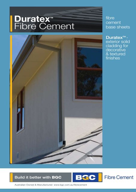
<strong>Duratex</strong>TM<br />
Fibre Cement<br />
Australian Owned & Manufactured www.bgc.com.au/fibrecement<br />
fibre<br />
cement<br />
base sheets<br />
<strong>Duratex</strong> TM -<br />
exterior solid<br />
cladding for<br />
decorative<br />
& textured<br />
finishes
History<br />
& Mission<br />
<strong>BGC</strong> Fibre Cement and<br />
Plasterboard is a proud Australian<br />
owned manufacturer of Fibre<br />
Cement and plasterboard<br />
products.<br />
<strong>BGC</strong> has state-of-the-art<br />
manufacturing facilities in Perth<br />
and distribution centres in all<br />
states of Australia and in<br />
New Zealand.<br />
Our distribution network ensures<br />
that our entire product range is readily<br />
available in all states of Australia.<br />
<strong>BGC</strong> has a team of technical<br />
specialists that can assist with<br />
all specification and design<br />
information to help ensure<br />
that you always<br />
‘build it better with <strong>BGC</strong>’.<br />
<strong>BGC</strong> has interests in:<br />
• residential and commercial building<br />
• building and construction products<br />
• contract mining<br />
• civil engineering construction<br />
and maintenance<br />
• quarrying<br />
• road transport<br />
• property ownership and<br />
management<br />
• insurance<br />
Our mission at <strong>BGC</strong> is simple –<br />
we want to ensure that people can<br />
always ‘build it better with <strong>BGC</strong>’.<br />
In keeping with our mission,<br />
we are constantly assessing and<br />
improving our products to ensure<br />
that we always provide cost<br />
effective, high quality and easyto-use<br />
products to the market.
03<br />
<strong>Duratex</strong><br />
Fibre Cement<br />
<strong>BGC</strong> DURATEXTM - June - 2011<br />
fibre<br />
cement<br />
base sheets<br />
<strong>BGC</strong> <strong>Duratex</strong> is<br />
designed to provide a<br />
solid substrate for applied<br />
decorative finishes when<br />
combined with proprietary<br />
jointing and coating systems.<br />
<strong>BGC</strong> <strong>Duratex</strong> provides a tough, durable,<br />
waterproof wall cladding system.<br />
<strong>Duratex</strong><br />
• Is tough and durable<br />
• Is a waterproof wall cladding system<br />
• Is fire resistant<br />
• Ideal for lightweight construction<br />
• Factory applied blue tint for ease of identification<br />
• Can be used in residential and<br />
commercial applications<br />
• Accepts a wide range of textured coatings<br />
• Complies with AS3959:2009- Construction of<br />
buildings in bushfire prone areas.<br />
• 7.5mm complies to BAL29<br />
• 9.0mm complies to BAL40
04<br />
Contents<br />
Product Description & Information 3-4<br />
Quality Systems 4<br />
Sheet Sizes 4<br />
Fire Resistance 5<br />
Handling & Storage 5<br />
Health and Safety 5<br />
Sheet Cutting & Drilling 5<br />
Thermal Bridging 5<br />
Sheet Layout 6<br />
Fixing Instructions 6<br />
Construction Details 6<br />
Framing 6<br />
Fasteners 6<br />
Sarking 7<br />
Joint Details 8-9<br />
Ground Clearance 9<br />
Horizontal Surfaces 9<br />
Window & Door Openings 10<br />
Joint & Coating Systems 11<br />
Maintenance 11<br />
<strong>Duratex</strong> as a Bracing 12-13<br />
Commercial Situations 14-15<br />
Warranty 15<br />
Bushfire & Boundary wall areas 16<br />
Product Description<br />
<strong>BGC</strong> <strong>Duratex</strong> is a fibre cement sheet that provides<br />
a solid substrate for applied decorative finishes.<br />
<strong>BGC</strong> <strong>Duratex</strong> sheets when combined with a proprietary<br />
jointing and coating system provide a tough, durable,<br />
waterproof wall cladding system that is immune to<br />
water damage, is fire resistant and is ideal for lightweight<br />
construction. It accepts a wide range of textured<br />
coatings and colours.<br />
Incorporating high-density polystyrene profiles<br />
bonded to the <strong>Duratex</strong> can further enhance the<br />
architectural effect.<br />
Energy Efficiency Considerations<br />
Energy efficiency requirements have been introduced<br />
into the BCA for both commercial and residential buildings.<br />
Thermal heat transfer in to and out of the building envelope<br />
can effect the running cost of the building and careful<br />
consideration of thermal heat transfer needs to be<br />
addressed by the architects, engineers and building<br />
designers. Thermal bridging through steel framing will<br />
diminish the total R-Value; thermal conductance, of the wall.<br />
Thermal breaks are required for steel framed buildings and<br />
should be installed between the lightweight steel CFS stud<br />
and or top hat sections and the <strong>Duratex</strong> cladding.<br />
Thermal breaks should have a minimum R-Value of<br />
0.2 or less.<br />
<strong>BGC</strong> DURATEXTM - June - 2011<br />
Product Information<br />
<strong>Duratex</strong> fibre cement sheets are manufactured to<br />
conform to the requirements of AS2908.2 Cellulose-Cement<br />
Products and are classified as Type A Category 2 sheet<br />
for external use.<br />
Mass<br />
The approximate weight of 7.5mm <strong>Duratex</strong> is<br />
10.28kg/m 2 and the approximate weight of 9.0mm<br />
<strong>Duratex</strong> is 12.34 kg/m 2.<br />
Appearance<br />
<strong>Duratex</strong> has a factory applied blue tint sealer on the face<br />
of the sheet. This sealer will facilitate the ease of application<br />
of the jointing compounds and texture coatings. The sheets<br />
are recessed on the two (2) long edges and on one (1) end.<br />
Deemed to Comply<br />
<strong>Duratex</strong> is approved by the Northern Territory Building<br />
Advisory Committee for Darwin Cyclonic Areas as detailed<br />
in the Deemed to Comply Manual drawings M/222/3<br />
and M/222/4.<br />
Quality Systems<br />
<strong>BGC</strong> Fibre Cement manufactures <strong>Duratex</strong> under the<br />
rigorous Quality Management System of the International<br />
Standard ISO 9002:1994 and is the holder of Licence<br />
Agreement number QEC2955/13.<br />
Sheet Sizes<br />
THICKNESS<br />
(mm)<br />
7.5<br />
9.0<br />
WIDTH<br />
(mm)<br />
900<br />
1200<br />
1200<br />
LENGTH<br />
(mm)<br />
1800 2400 2440 2725 3000<br />
x x x<br />
x x x x<br />
x x
05<br />
Fire Resistance<br />
<strong>BGC</strong> <strong>Duratex</strong> has been tested for and passed the<br />
Early Fire Hazard Property criteria in compliance with<br />
AS/NZS 1530.3 and AS/NZS 3837 and is deemed a<br />
Group 1 Material in accordance with the BCA, Volume 1.<br />
Specification A2.4; Fire Hazard Properties.<br />
AS/NZS 1530.3; Early Fire Hazard Properties.<br />
This report deemed the following Early Fire Hazard Properties<br />
• Ignition Index 0<br />
• Spread of Flame Index 0<br />
• Heat Evolved Index 0<br />
• Smoke Developed Index 0-1<br />
Handling & Storage<br />
<strong>Duratex</strong> must be stacked flat, up off the ground and<br />
supported on equally spaced (max 300mm) level gluts.<br />
The sheets must be kept dry, preferably by being stored<br />
inside a building. When stored outdoors they must be<br />
protected from the weather.<br />
Care should be taken to avoid damage to the ends,<br />
edges and surfaces.<br />
Sheets must be dry prior to being fixed, jointed or coated.<br />
Sheets must be carried on edge.<br />
Health and Safety<br />
<strong>BGC</strong> <strong>Duratex</strong> is manufactured from cellulose fibre,<br />
finely ground sand, Portland cement and additives.<br />
As manufactured, the product will not release airborne dust<br />
but, during drilling, cutting and sanding operations cellulose<br />
fibres, silica and calcium silicate dust may be released.<br />
Breathing in fine silica dust is hazardous, prolonged<br />
exposure (usually over several years) may cause<br />
bronchitis, silicosis or cancer.<br />
Avoid Dust Inhalation<br />
When cutting sheets, work in a well-ventilated area and<br />
use the methods recommended in this literature to minimise<br />
dust generation. If using power tools wear an approved<br />
(P1 or P2) dust mask and safety glasses.<br />
These precautions are not necessary when stacking,<br />
unloading or handling fibre cement products.<br />
For further information or a Material Safety Data Sheet<br />
contact the nearest <strong>BGC</strong> Fibre Cement Sales Office or go to<br />
www.bgc.com.au/fibrecement<br />
<strong>BGC</strong> DURATEXTM - June - 2011<br />
Sheet Cutting & Drilling<br />
<strong>Duratex</strong> may be cut to size on site. If using power tools<br />
for cutting, drilling or sanding they must be fitted with<br />
appropriate dust collection devices or alternatively an<br />
approved (P1 or P2) dust mask and safety glasses shall<br />
be worn.<br />
It is recommended that work always be carried out<br />
in a well-ventilated location.<br />
The most suitable cutting methods are:<br />
• Score and Snap<br />
Score the sheet face 4 or 5 times with a ‘score and<br />
snap’ knife. Support the scored edge and snap the<br />
sheet upward for a clean break.<br />
• Hand Guillotine<br />
Cut on the off-cut side of the line to allow for<br />
the blade thickness.<br />
• Drilling<br />
Use normal high-speed drill bits. Do not use the drill’s<br />
hammer function. For small round holes, the use of a<br />
hole-saw is recommended.<br />
For small rectangular or circular penetrations, drill a<br />
series of small holes around the perimeter of the cut<br />
out. Tap out the waste piece from the sheet face while<br />
supporting the underside of the opening to avoid<br />
damage. Clean rough edges with a rasp.<br />
Large rectangular openings are formed by deeply<br />
scoring the perimeter of the opening. Next, form a hole<br />
in the centre of the opening (refer method above) then<br />
saw cut from the hole to the corners of the opening.<br />
Snap out the four triangular segments. Clean rough<br />
edges with a rasp.<br />
Thermal Bridging<br />
Thermal breaks are required for steel framed buildings<br />
in walls enclosing habitable and/or useable spaces.<br />
Careful consideration of thermal heat transfer and the<br />
position of thermal breaks need to be addressed by the<br />
architects, engineers and building designers.<br />
Balustrades, parapets and other non enclosing wall<br />
elements may not require thermal bridging, except where<br />
the possibility of high thermal heat transfer exists through<br />
the steel CFS sections to the main structural steel element<br />
of the building.<br />
Thermal breaks should be installed between the <strong>Duratex</strong><br />
and the steel framing.<br />
Thermal bridging is to be no less than R 0.2.<br />
For further information refer to section of the National<br />
Construction Code Series/BCA.
06<br />
Sheet Layout<br />
<strong>Duratex</strong> must be joined over a stud and the ends of the<br />
sheet to be supported by the top/bottom plate. Butt sheets<br />
tightly together except where control joints are employed<br />
or at an internal corner.<br />
On internal corners leave a 3~5mm gap for polyurethane<br />
sealant. (Refer Figure 5)<br />
At external corners, the sheet joint must finish flush -<br />
do not leave any gap. (Refer Figure 6)<br />
Vertical fixing of sheets is recommended. When fixing more<br />
than one sheet high, vertical joints must be in line.<br />
Framing studs should be spaced at maximum centres of<br />
600 mm so they will conform to the sheet widths.<br />
Horizontal fixing of <strong>Duratex</strong> is permissible only where<br />
the cladding depth does not exceed the sheet width,<br />
ie 1200 mm.<br />
Fixing Instructions<br />
The success of any jointing system is very much dependent<br />
upon the correct construction of the framing, the fixing of the<br />
<strong>Duratex</strong>, and the application of the jointing materials.<br />
<strong>Duratex</strong> sheets must be dry before fixing to the framing<br />
structure. Sheet cuts, which are to be flush jointed, must<br />
be recessed on site (see Figure 1). The Hitachi ‘Easy Bevel’<br />
(Model EB100) is specifically designed for this purpose.<br />
Figure 1 - <strong>Duratex</strong> On Site Recessing<br />
<strong>BGC</strong> DURATEXTM - June - 2011<br />
40mm<br />
Bevelled Edge 1.5mm<br />
Construction Details - Framing<br />
<strong>Duratex</strong> is suitable for use with both timber and<br />
lightweight steel framing.<br />
General<br />
• Framing must be constructed to comply with the<br />
Building Code of Australia.<br />
• The framing must be set to a true plane to ensure<br />
a straight finish to the wall.<br />
• Studs must be spaced at a maximum of 600 mm centres.<br />
• Noggings must be spaced at a maximum of<br />
1350 mm centres. See Figure 2.<br />
• <strong>Duratex</strong> wall sheets must not be joined off the framing.<br />
Timber Framing<br />
Timber framing must comply with AS 1684.2 & .3 1999<br />
Residential Timber - Framed Construction.<br />
<strong>Duratex</strong> must not be fixed to wet framing. It is strongly<br />
recommended that kiln dried timber is used for framing.<br />
If sheets are fixed to ‘wet’ framing, problems may occur<br />
at a later date due to excessive timber shrinkage.<br />
Metal Framing<br />
Metal framing must comply with AS 3623 - 1993 Domestic<br />
Metal Framing.<br />
<strong>Duratex</strong> may be fixed directly to lightweight metal framing.<br />
The metal framing must not exceed 1.6 mm in thickness.<br />
If <strong>Duratex</strong> is used with rigid steel framing, it must be<br />
battened out with either timber or lightweight steel battens<br />
prior to fixing.<br />
Timber battens must have a minimum thickness of 40 mm<br />
to allow adequate nail penetration. Battens supporting sheet<br />
joints must have a minimum actual face width of 45 mm.<br />
Fasteners<br />
For general applications <strong>Duratex</strong> sheets are fixed<br />
to timber framing using 30 x 2.8 mm galvanised<br />
flat-head nails.<br />
30 x 2.8 mm Galvanised Flat Head Nail<br />
For fixing <strong>Duratex</strong> sheets to metal frames, use<br />
No. 8 x 20mm galvanised self-embedding head screws.<br />
No.8 x 20 mm Galvanised Self-embedding Head Screw
07<br />
Sheet Fixing<br />
<strong>Duratex</strong> sheets are to be installed vertically and fixing to<br />
be spaced at a maximum of 200 mm centres.<br />
For details on bracing see pages 13 & 14 where fasteners are<br />
at 150 mm around the perimeter and 200 mm centres in the<br />
body of the sheet.<br />
Do not place fixings closer than 12mm from sheet edges, or<br />
closer than 50mm from sheet corners.<br />
The sheet must be held firmly against the framing when fixing<br />
to ensure breakout does not occur on the back.<br />
Figure 2 - Sheet Fixing<br />
Fixings 12mm min<br />
from Sheet Edge<br />
<strong>BGC</strong> DURATEXTM - June - 2011<br />
200<br />
mm<br />
200<br />
mm<br />
200<br />
mm<br />
Nail Spacing - 200mm Maximum<br />
Sarking<br />
In wall cladding applications, the installation of a vapour<br />
permeable perforated sarking between <strong>Duratex</strong> and the<br />
framing is recommended.<br />
Under windy conditions the building’s internal pressure<br />
will generally be less than the external air pressure, this will<br />
tend to draw water through flashing and seals if sarking<br />
is not used.<br />
Use of a reflective perforated sarking will enhance the<br />
insulation properties of the cladding system.<br />
Fixings 50mm min<br />
from Sheet Corner<br />
Maximum Stud Centres<br />
600mm<br />
Maximum Nogging<br />
Centres 1350 mm<br />
Sarking
08<br />
Joint Details<br />
Figure 3 - Joint Details Timber Frame Construction Figure 6 - External Corner Joint<br />
<strong>Duratex</strong> Sheet 12 mm minimum<br />
30 x 2.8 mm<br />
Galvanised<br />
flat-head nails<br />
Figure 4 - Joint Details Steel Frame Construction<br />
<strong>Duratex</strong> Sheet<br />
No.8 x 20 mm<br />
Galvanised Self-drilling<br />
self embedding screws<br />
Note: Where lighter<br />
gauge steel frame is used,<br />
it may be necessary to<br />
pre-drill and countersink<br />
the <strong>Duratex</strong> sheets.<br />
Timber Stud<br />
Figure 5 - Internal Corner Joint<br />
Framing<br />
<strong>BGC</strong> DURATEXTM - June - 2011<br />
3-5 mm gap<br />
sealed with<br />
polyurethane sealant<br />
Flashing<br />
Sarking<br />
12 mm minimum<br />
<strong>Duratex</strong> Sheet<br />
Sarking<br />
Metal Framing<br />
Max. 1.6 mm thick<br />
Sarking<br />
External Angle<br />
PVC or<br />
Stainless Steel<br />
Sarking<br />
Stud<br />
6 mm<br />
<strong>Duratex</strong> Sheets<br />
6mm Control Joint<br />
Structural Break with<br />
top and bottom plates<br />
Butt Edge<br />
Finish<br />
Control Joints<br />
Figure 7 - Vertical Relief Joint<br />
Figure 8 - Vertical Control Joint<br />
<strong>Duratex</strong> Sheet<br />
Flashing<br />
Sarking<br />
Timber Framing<br />
Bond breaker tape<br />
6 mm gap filled with polyurethane sealant<br />
Texture coating must not cover sealant<br />
Stud<br />
Timber Framing<br />
Framing<br />
Where a continuous wall is longer than 4800mm but<br />
no longer than 6000mm, a vertical relief joint must<br />
be incorporated in this wall structure (see Figure 7).<br />
Where the continuous wall is over 6000mm in length,<br />
a full vertical control joint is required at a maximum<br />
of 6000mm. The vertical control joint must form a<br />
complete break in the structural element, including the<br />
top and bottom plates and not just the sheet cladding.<br />
Use square cut edges to form these movement joints<br />
(see Figure 8).<br />
Relief and control joints require a 6mm gap between<br />
sheets and are best incorporated in the structure<br />
at window and door opening or behind where a<br />
downpipe is to be located.<br />
Sarking<br />
Bond breaker tape<br />
6 mm<br />
<strong>Duratex</strong> Sheets<br />
6 mm gap filled with polyurethane sealant Coating must not cover sealant
09<br />
Horizontal Relief Joints Wall Abutment<br />
Horizontal Relief Joints must be provided if the wall<br />
height exceeds 5400mm or wherever floor joists occur.<br />
(This is imperative if non-kiln dried timber floor<br />
joists or framing is used).<br />
Alternatives to this relief joint are:<br />
• To use a horizontal “Z” flashing strip.<br />
• Let the floor joists overhang the top plates of the<br />
lower floor to create a sealed sheet overlap.<br />
Figure 9 - Typical Horizontal Relief Joint<br />
Bottom Plate<br />
(upper floor)<br />
Flooring<br />
Floor Joist<br />
Top Plate<br />
(lower floor)<br />
The Architectural profile must overhang the bottom sheet<br />
by a minimum of 25 mm.<br />
Horizontal Relief Joints<br />
<strong>Duratex</strong> must not be applied to nominal horizontal<br />
surfaces such as the tops of parapets, sills, decking<br />
upstands, etc. These surfaces must be sloped a minimum<br />
of 15 o to the horizontal for light-texture finishes, or a<br />
minimum of 30 o for heavy-texture finishes. The alternative<br />
is to install a fully sealed and waterproof membrane system<br />
immediately under the cladding on the horizontal surface<br />
or install a capping.<br />
<strong>BGC</strong> DURATEXTM - June - 2011<br />
Sarking<br />
<strong>Duratex</strong> Sheet<br />
Nailed to Bottom Plate<br />
Architectural Profile<br />
or similar<br />
(by coating applicator)<br />
Nail in centre<br />
of floor joist<br />
6-8 mm gap<br />
Do not bond<br />
architectural<br />
profile section<br />
below sheet joint<br />
Horizontal “Z” Flashing<br />
<strong>Duratex</strong> Sheet<br />
Nailed to Top Plate<br />
Control Joints must be employed when an addition is<br />
constructed onto an existing building or when a masonry<br />
wall adjoins a timber or steel framed construction.<br />
Control Joints should be constructed using 9 mm diameter<br />
backing rod and polyurethane sealant on abutment to<br />
existing masonry walls.<br />
Timber<br />
Framing<br />
Sarking<br />
Ground Clearance<br />
<strong>Duratex</strong> must not be used in situations where it<br />
will be below ground or where it will be buried in the ground.<br />
The ground clearances as set out in figure 10 must be<br />
adhered to at all times.<br />
Figure 10 - Ground Clearance<br />
6 mm Control Joint<br />
Structural break with<br />
top and bottom plates<br />
Packing<br />
Dampcourse<br />
<strong>Duratex</strong><br />
sheets Backing Rod<br />
9mm diam<br />
Polyurethane Sealant must NOT<br />
be covered by textured coating<br />
Timber Stud<br />
Bottom Plate<br />
Damp Proof<br />
Course<br />
Concrete Slab<br />
Timber to overhang<br />
concrete by 2-3 mm<br />
Sarking<br />
Masonry<br />
Wall<br />
<strong>Duratex</strong> Sheet<br />
50mm sheet overhang<br />
100 mm Minimum<br />
clearance to ground level
10<br />
Figure 11 - Typical Window Frame Weather Proofing<br />
Lintel Details<br />
Sarking<br />
<strong>Duratex</strong> Sheet<br />
Compatible<br />
Flashing<br />
Sealant<br />
Jamb Details<br />
Typical Aluminium<br />
Window Frame<br />
Sealant<br />
<strong>Duratex</strong> Sheet<br />
Compatible Flashing<br />
Sill Details<br />
Sealant<br />
Compatible<br />
Flashing<br />
<strong>Duratex</strong> Sheet<br />
Sarking<br />
<strong>BGC</strong> DURATEXTM - June - 2011<br />
Internal Wall<br />
Lining<br />
Internal Wall<br />
Lining<br />
Sarking<br />
Internal<br />
Wall Lining<br />
Window and Door Openings<br />
To reduce the incidence of cracks appearing in the jointing,<br />
flush jointed sheets should be cut in (200 mm minimum)<br />
around window and door openings as depicted in Figure 12.<br />
If a sheet joint must coincide with the corner of an opening,<br />
<strong>BGC</strong> Fibre Cement recommend installation of a relief joint<br />
to control cracking. See Figure 7.<br />
Figure 12 - Typical Window Frame Weather Proofing<br />
Eaves Detail<br />
4.5 mm Durasheet<br />
Eaves Lining<br />
200 mm min 200 mm min<br />
250 mm min<br />
Where there is an eave on the building, the <strong>Duratex</strong><br />
sheet must finish a minimum 6.0 mm short of the eave.<br />
The 6.0 mm gap can be filled with polyurethane sealant<br />
or a timber moulding can be fitted. Texture coating must<br />
not cover the sealant or the timber.<br />
Leave a 6 mm gap<br />
between the eave sheet<br />
and <strong>Duratex</strong><br />
<strong>Duratex</strong>
11<br />
Joint and Coating Systems Maintenance<br />
Proprietary joint and coating systems for fibre cement<br />
sheets have been developed by a number of coating<br />
manufacturers. The jointing and coating system must be<br />
applied by applicators recommended as suitable by the<br />
joint and coating manufacturer.<br />
The selected joint and coating system must be applied<br />
to dry, clean sheets only. Application must be completed<br />
within 3 months of the sheets being fixed on site, shorter<br />
in harsher conditions.<br />
It is strongly recommended that dark colours be avoided<br />
as they may cause high temperature variations within the<br />
substrate, leading to excessive thermal movement.<br />
Heavier-texture coatings are preferred over smoother finishes,<br />
as any minor surface imperfections are less likely to become<br />
apparent in critical lighting conditions.<br />
Note: <strong>Duratex</strong> is not recommended to<br />
have a paint finish<br />
Figure 13 - Typical Joint and Coating Detail<br />
Recessed Edge Sheet Fastener<br />
<strong>Duratex</strong> Sheet<br />
Proprietary<br />
Jointing System<br />
<strong>BGC</strong> DURATEXTM - June - 2011<br />
Proprietary<br />
Coating System<br />
The <strong>Duratex</strong> cladding system must be maintained to<br />
ensure that the system continues to prevent moisture<br />
entering the building.<br />
Check flashing, sealant joints and coating systems annually:<br />
• Flashings must continue to perform<br />
their design function.<br />
• Rake out and replace damaged or cracked sealant.<br />
• Replace damaged sheets and reinstate coating system<br />
as for new work.<br />
Coatings must be maintained in accordance with the<br />
coating manufacturer’s instructions.
12<br />
Bracing<br />
<strong>BGC</strong> 7.5mm <strong>Duratex</strong> can be used to provide bracing<br />
to resist racking loads due to wind loadings when<br />
installed vertically.<br />
Where 7.5mm <strong>Duratex</strong> is used to provide bracing on<br />
timber dwellings, the Australian Standard for “Residential<br />
timber-framed construction” must be adhered:<br />
AS1684.2-1999 (Non-cyclonic areas)<br />
AS1684.3-1999 (Cyclonic areas)<br />
Racking forces due to wind loading shall be calculated<br />
as per these Australian Standards.<br />
For bracing data on other construction methods and<br />
applications, contact your <strong>BGC</strong> Fibre Cement Sales Office.<br />
Nominal Wall Bracing<br />
Up to 50% of the total bracing requirements can be<br />
supplied by <strong>BGC</strong> 7.5mm <strong>Duratex</strong> sheeting installed<br />
normally. To be eligible for inclusion in calculations as<br />
nominal wall bracing:<br />
• The minimum length of each nominal bracing panel<br />
shall be 450mm.<br />
• Nominal bracing shall be distributed evenly<br />
throughout the building.<br />
The Bracing Capacity for nominal bracing is given in<br />
the following table:<br />
Nominal Sheet Bracing Walls<br />
METHOD<br />
Sheeted one side only<br />
Sheeted two sides<br />
<strong>BGC</strong> DURATEXTM - June - 2011<br />
BRACING<br />
CAPACITY (KNm)<br />
0.45<br />
0.75<br />
Figure 14 - <strong>Duratex</strong> Bracing Capacity<br />
Using Tie Down Bolts<br />
150mm<br />
max<br />
Fasteners 12mm min from sheet edges<br />
Fasteners 50mm min. from sheet corners<br />
200mm<br />
max<br />
Stud Centres<br />
See bracing capacity<br />
Fastener Spacing<br />
7.5mm<br />
<strong>Duratex</strong><br />
M12 Tie down bolts at<br />
1200mm max centres<br />
With 50 x 50 x 2mm washer<br />
When using tie down bolts, fasteners are to be fixed at<br />
150 mm max around sheet perimeter and 200 mm<br />
max in the body of the sheet.<br />
STUD CENTRE<br />
(mm)<br />
600<br />
450<br />
*Ultimate Limit State design.<br />
Tie down<br />
Bolts<br />
100mm<br />
max from<br />
stud face<br />
edge on<br />
each bracing<br />
panel<br />
CLADDING BRACING CAPACITY<br />
(k/N/m)ULS*<br />
One Face Only<br />
One Face Only<br />
These results are from testing on JD5 Grade timber. If hardwood<br />
frames (JD2) are used, the ULS will increase by 12.5%.<br />
Permisable Stress Design (PSD) = Ultimate Limit State (ULS)<br />
1.5<br />
3.6<br />
3.75
13<br />
Bracing<br />
Figure 15 gives the design bracing capacity for panels<br />
secured with anchor rods. This table can be considered<br />
to be an addition to Table 8.18, AS1684.2 -<br />
1999/AS1684.3 - 1999.<br />
Figure 15 - <strong>Duratex</strong> Bracing Capacity<br />
Using Anchor Rods<br />
Fastener Spacing<br />
When using anchor rods, fasteners are to be fixed at<br />
150 mm max around sheet perimeter and 200 mm<br />
max in the body of the sheet.<br />
STUD CENTRE<br />
(mm)<br />
600<br />
450<br />
Fasteners 12mm min from sheet edges<br />
Fasteners 50mm min. from sheet corners<br />
M12 Anchor rods with<br />
50 x 50 x 2mm wahers<br />
Minimum 2 (one each side bracing panel)<br />
Maximum Centres 2400mm<br />
150mm<br />
max<br />
200mm<br />
max<br />
Stud Centres<br />
See bracing capacity<br />
*Ultimate Limit State design.<br />
One Face Only<br />
One Face Only<br />
These results are from testing on JD5 Grade timber. If hardwood<br />
frames (JD2) are used, the ULS will increase by 12.5%.<br />
Permisable Stress Design (PSD) = Ultimate Limit State (ULS)<br />
1.5<br />
+Calculated through interpolation.<br />
<strong>BGC</strong> DURATEXTM - June - 2011<br />
Intermediate M12<br />
tie down bolts with<br />
50 x 50 x 2mm washers<br />
1200mm max centres<br />
7.5mm<br />
<strong>Duratex</strong><br />
M12 anchor<br />
rods with<br />
50 x 50 x 2mm<br />
washer<br />
Anchor rods<br />
100mm max<br />
from stud<br />
face edge on<br />
each bracing<br />
panel<br />
CLADDING BRACING CAPACITY<br />
(k/N/m)ULS*<br />
5.1<br />
5.3+<br />
Panels Height Greater Than 2700mm<br />
The bracing capabilities, Figure 14 and 15 are applicable<br />
to a maximum panel height of 2700mm.<br />
For panel heights greater than 2700mm the bracing capacity<br />
shall be reduced using the panel height multipler given in<br />
the following table:<br />
Bracing Capacity - Panel Height Multiplier<br />
WALL HEIGHT<br />
(mm)<br />
3000<br />
3300<br />
3600<br />
3900<br />
4200<br />
Panel Length Less Than 900mm<br />
The bracing capabilities, Figures 14 and 15 are applicable<br />
to a minimum panel length of 900mm. Effective bracing is<br />
achievable with panel lengths down to 450mm. Reduce the<br />
bracing capacity for panel between 450mm and 900mm<br />
long, using panel length multiplier given in the following table:<br />
Bracing Capacity - Panel Height Multiplier<br />
WALL HEIGHT<br />
(mm)<br />
850<br />
800<br />
750<br />
700<br />
650<br />
600<br />
550<br />
500<br />
450<br />
Thermal Break Details<br />
MULTIPLIER<br />
0.90<br />
0.80<br />
0.75<br />
0.70<br />
0.64<br />
MULTIPLIER<br />
0.92<br />
0.83<br />
0.75<br />
0.66<br />
0.58<br />
0.50<br />
0.42<br />
0.33<br />
0.25<br />
Thermal breaks are required for steel framed habitable<br />
buildings. Careful consideration of thermal heat transfer<br />
and the position of thermal breaks need to be addressed<br />
by the architects, engineers and building designers.<br />
Thermal breaks should be installed between the lightweight<br />
steel CFS stud and or top hat sections and the <strong>Duratex</strong><br />
cladding. Non-enclosing wall elements may not require<br />
thermal bridging, except where the possibility of high<br />
thermal heat transfer exists through to the main structural<br />
steel element of the building.
14<br />
<strong>Duratex</strong> 9.0mm in Commercial Situations<br />
<strong>BGC</strong> <strong>Duratex</strong> 9.0mm offers the designer and building<br />
owner a masonry look solution, for institutional, commercial<br />
and industrial buildings.<br />
<strong>Duratex</strong> clad walls up to 6m long and 1.2m, 3.0m or 4.2m<br />
high, can be constructed using a standard technique flush<br />
jointing system, supplied by the same manufacturer of the<br />
high build coating system.<br />
For a long trouble free service life of <strong>Duratex</strong>, <strong>BGC</strong> Fibre<br />
Cement recommends that prior to installation and fixing,<br />
all surfaces are sealed with a sealer compatible with the<br />
high-build coating system on the front face.<br />
Design<br />
Design, construction and control joints are kept to a<br />
minimum and coincide with the building articulation and<br />
framing layout, and in accordance with the <strong>Duratex</strong><br />
design consultant’s detailing.<br />
Fascias are generally 1.2m high, with the sheets laid and<br />
fixed horizontally. The Fascias and Facades higher than<br />
1.2m are fixed vertically.<br />
<strong>BGC</strong> <strong>Duratex</strong> 9.0mm sheets are 1200mm wide x 2400mm<br />
and 3000mm long, with two (2) recessed long edges and<br />
one (1) short edge, are primed on both faces and all edges<br />
and are available ex-stock.<br />
Framing<br />
Framing can be either in timber or lightweight cold-formedsection<br />
(CFS) steel Top-Hat sections or C- section studs.<br />
45mm face-width timber and 38mm face-width Cee stud<br />
framing is typically used in smaller framed building or infill<br />
panels, up to 3.0m high.<br />
For larger facades, up to 4.2m high, 75mm x 35mm x<br />
1.15mm Top-Hat sections, fixed to structural CFS girts,<br />
are used.<br />
Top-Hat and stud spacing is set at 600mm maximum for<br />
low wind speed areas, up to 1.5kPa wind pressure, and<br />
400mm maximum spacing for high wind pressure areas,<br />
up to 2.5kPa; dependent on girt spacing.<br />
Timber and CFS stud framing must have a mid-point row of<br />
noggins for frames above 2.4m high, and where the façade<br />
exceeds 1.2m high, the sheets are to be set out vertically.<br />
<strong>BGC</strong> DURATEXTM - June - 2011<br />
Fixing<br />
<strong>BGC</strong> <strong>Duratex</strong> 9.0mm sheets are fixed to the support<br />
framing at 200mm maximum centres along the sheet edges<br />
and over intermediate supports.<br />
Fixing must be at 12mm minimum from the sheet edges and<br />
75mm minimum from the corners.<br />
<strong>Duratex</strong> 9mm fixing detail<br />
Sc<br />
Sp<br />
Se<br />
Sp<br />
Sb<br />
Sp<br />
Fastener Centres<br />
Sp Sheet perimeter 200mm max<br />
Sb Sheet body 200mm max<br />
Se 12mm min from sheet edges<br />
Sc 75mm min from sheet corners<br />
Se<br />
Sheets fixed vertically Sheets fixed horizontally<br />
Sheets fixed to lightweight CFS steel Top Hat and Stud<br />
supports are placed over 6mm x 50mm thermal bridging<br />
tape, such as Norton V768 or UNISIL 3208, or equivalent.<br />
Countersunk, self embedding winged, self drilling<br />
screws 32mm long complying with AS3655 are to be<br />
used when fixing to lightweight CFS steel support framing.<br />
Sheets are to be pre drilled if winged screws are not used.<br />
<strong>Duratex</strong> 9mm screw fixed set joint detail<br />
Steel Top hat section<br />
Fastener 75 mm min<br />
from corner<br />
Fixing to timber framing is effected using 40 x 2.8mm<br />
galvanized fibre cement nails, driven flush to the<br />
sheet surface.<br />
Sc<br />
Sp<br />
Fastener<br />
12mm min<br />
from edge<br />
Recessed edge<br />
Proprietary<br />
coating system<br />
Sb<br />
Sp<br />
Proprietary<br />
Jointing system
15<br />
Control Joints<br />
Vertical and horizontal control joints are required where the<br />
wall length exceeds 6m long and height exceeds 3m and<br />
as required by the building design, articulation and framing<br />
layout, in accordance with the design consultants dealing.<br />
Construction and control joints allow for relative movements<br />
between the building mainframes, subframes and cladding<br />
systems, due to building settlement, thermal movements<br />
and other forces. Flexible/slip joints allow for these movements<br />
and consist of a sealed joint, bond breaker tape<br />
and fixings.<br />
Where CFS Top Hat sections are used, 10mm construction<br />
control joints are affected over two separate supporting<br />
Top Hats, as shown in the diagram below.<br />
Polyurethane sealant<br />
Bond breaker<br />
foam strips<br />
0.75mm nom.<br />
galv. backing strip<br />
pop rivet to one<br />
side only<br />
Module slip/control joints over CFS Top Hat framing must<br />
have a 10mm gap between each adjacent module of<br />
<strong>BGC</strong> <strong>Duratex</strong> panels, as shown in the diagram below.<br />
<strong>BGC</strong> <strong>Duratex</strong><br />
Bond breaker<br />
foam strips<br />
75 mm<br />
75 mm<br />
Polyurethane sealant<br />
Horizontal joints are similar to the vertical jointing systems<br />
and may be expressed or have architectural details applied.<br />
Where openings occur, such as doors, windows, signage<br />
apertures and the like, relief joints should be used to prevent<br />
the possibility of system failure due to induced stresses.<br />
These joints are similar to the module slip/control joint,<br />
with a nominal 3mm gap between sheets, in line with<br />
the openings vertical edge.<br />
<strong>BGC</strong> DURATEXTM - June - 2011<br />
Gap 10mm nom.<br />
Steel stop hat<br />
sections<br />
Control joint in<br />
structure<br />
Steel stop hat<br />
sections<br />
Gap<br />
10mm nom.<br />
Warranty<br />
<strong>BGC</strong> warrants its products to be free from defects caused<br />
by faulty manufacture or materials. If any of its products are<br />
so defective the Company will at its option, repair or replace<br />
them, supply equivalent replacement products or reimburse<br />
the purchase price.<br />
This warranty shall not apply to any loss or consequential<br />
loss suffered through or resulting from defects caused by<br />
faulty manufacture or materials.<br />
Fittings or accessories supplied by third parties is beyond<br />
the control of <strong>BGC</strong> and as such is not warranted by <strong>BGC</strong>.
16<br />
Bushfire and Boundary Wall Areas Boundary/Exterior Walls<br />
<strong>BGC</strong> <strong>Duratex</strong> TM is eminently suited for both bushfire and<br />
boundary wall applications in residential and multi residential<br />
buildings.<br />
<strong>BGC</strong> <strong>Duratex</strong> TM 7.5mm can be used as a stand alone<br />
product to achieve up to BAL29 and <strong>BGC</strong> <strong>Duratex</strong> 9.0mm<br />
can be used as a stand alone product to achieve up to BAL<br />
40 when fixed direct to frame as per the fixing instructions in<br />
this manual.<br />
<strong>BGC</strong> <strong>Duratex</strong> TM when used in conjunction with <strong>BGC</strong> 16mm<br />
Wet Area Fireboard will comply with the requirements of<br />
AS3959:2009 and AS1530.4 to achieve BAL FZ>10 as<br />
well as 60 minute and 90 minute boundary wall systems.<br />
Bushfire AS3959:2009 applications.<br />
AS3959:2009 sets out a series of Bushfire threat levels to<br />
buildings described as BAL (Bushfire Attack Levels) as<br />
follows: BAL-Low, BAL-12.5, BAL-19, BAL-29, BAL-40<br />
or BAL-FZ (Flamezone).<br />
<strong>BGC</strong> <strong>Duratex</strong> 7.5mm may be used to achieve a BAL29 or<br />
BAL FZ>10 when used in conjunction with 16mm Wet Area<br />
Fireboard. – <strong>BGC</strong> <strong>Duratex</strong> 9.0mm may be used to achieve a<br />
BAL40 or BAL FZ>10 when used in conjunction with 16mm<br />
Wet Area Fireboard.<br />
<strong>BGC</strong> One Sided FRL Test July 2009 Load Bearing<br />
<strong>BGC</strong> One Sided FRL Test July 2009 Load Bearing<br />
One layer of<br />
<strong>BGC</strong> 16mm Wet<br />
Area Fireboard<br />
One layer of<br />
10mm<br />
Plasterboard<br />
Noggings at<br />
1350mm max<br />
Studs at<br />
600mm<br />
maximum<br />
centres<br />
Taped with <strong>BGC</strong><br />
BaseCoat 60 and<br />
paper tape, 2 nd coat<br />
<strong>BGC</strong> BaseCoat 60<br />
<strong>BGC</strong> DURATEXTM - June - 2011<br />
Caulk perimeter<br />
with fire-rated<br />
mastic.<br />
300mm max<br />
Caulk perimeter<br />
with fire-rated<br />
mastic.<br />
<strong>BGC</strong> <strong>Duratex</strong> TM in conjunction with <strong>BGC</strong> 16mm Wet Area<br />
Fireboard can achieve both 60/60/60 and 90/90/90 FRL fire<br />
ratings from the outside as required by the BCA.<br />
Where an exterior wall is required to achieve 60/60/60 FRL<br />
(Fire Resistance Level) from the outside, 1 layer of 16mm<br />
<strong>BGC</strong> Wet Area Fireboard installed with <strong>BGC</strong> <strong>Duratex</strong> TM over<br />
the Wet Area Fireboard will meet minimum BCA<br />
requirements. Similarly 2 layers of 16mm <strong>BGC</strong> Wet Area<br />
Fireboard used in conjunction with <strong>BGC</strong> <strong>Duratex</strong> TM will<br />
achieve 90/90/90 from the outside.<br />
Note: All external walls must have sarking beneath the<br />
<strong>BGC</strong> <strong>Duratex</strong> TM . No adhesives are to be used when<br />
installing Wet Area Fireboard and the <strong>BGC</strong> <strong>Duratex</strong> TM .<br />
Nails or screws must be used.<br />
For fixing details of the <strong>BGC</strong> Wet Area Fireboard refer<br />
to the <strong>BGC</strong> Fire and Acoustic Guide.<br />
For more information please contact your nearest<br />
<strong>BGC</strong> Fibre Cement office.<br />
200mm max<br />
200mm max<br />
Fasteners<br />
12mm min from<br />
sheet edges<br />
200mm max<br />
Fasteners<br />
50mm min from<br />
sheet corners<br />
200mm max<br />
One layer of<br />
<strong>BGC</strong> 7.5mm<br />
<strong>Duratex</strong><br />
Fasteners<br />
50mm min from<br />
sheet corners
17<br />
Notes<br />
<strong>BGC</strong> DURATEXTM - June - 2011
18<br />
Notes<br />
<strong>BGC</strong> DURATEXTM - June - 2011
19<br />
Notes<br />
<strong>BGC</strong> DURATEXTM - June - 2011
To contact<br />
your nearest <strong>BGC</strong><br />
stockist, please call:<br />
Adelaide<br />
Telephone<br />
08 8250 4962<br />
Brisbane<br />
Telephone<br />
07 3271 1711<br />
Melbourne<br />
Telephone<br />
03 9392 9444<br />
Perth<br />
Telephone<br />
08 9334 4900<br />
Sydney<br />
Telephone<br />
02 9632 2100<br />
New Zealand<br />
Telephone<br />
0011 64 9264 1457<br />
bgc.com.au/fibrecement<br />
Safe working practices - Please wear a P1 or P2 mask and safety goggles (approved to AS/NZW1337 standards) whilst cutting<br />
or installing <strong>Duratex</strong> TM. <strong>Duratex</strong> TM can be safely handled during unloading or stacking without the use of these precautions.<br />
Cleaning up - Always wet down your work area when cutting <strong>Duratex</strong> TM, to ensure that dust is managed.<br />
Dispose of any vacuumed dust with care and using containment procedures.<br />
Design by The SHAPE Group www.theshapegroup.com.au<br />
<strong>BGC</strong> Fibre Cement is a proud<br />
Australian owned manufacturer<br />
of fibre cement products.<br />
<strong>BGC</strong> Fibre Cement provides<br />
builders, developers and architects<br />
with a range of design alternatives<br />
and innovative products, such as:<br />
EXTERIOR PRODUCTS<br />
AND APPLICATIONS<br />
Innova TM range of products:<br />
• Duragrid TM Residential and<br />
Duragrid TM Light Commercial<br />
A lightweight façade giving<br />
a modern and durable finish.<br />
• Duracom TM<br />
A compressed fibre cement<br />
facade system.<br />
• Nuline TM<br />
A weatherboard style<br />
cladding system.<br />
• Stonesheet TM<br />
A purpose designed substrate<br />
for stone tile facades.<br />
<strong>BGC</strong> Fibre Cement range<br />
of products:<br />
• DurasheetTM Ideal for the cladding of gables<br />
and lining of eaves. Can also<br />
be used on commercial<br />
soffits and cladding on non<br />
impact areas.<br />
• DuraplankTM Available in Smooth,<br />
Woodgrain and Rusticated<br />
finishes, is ideal for exterior<br />
cladding of upper storey<br />
conversions or ground<br />
level extensions.<br />
• <strong>Duratex</strong>TM A base sheet used for textured<br />
coatings on exterior wall<br />
applications.<br />
• DuralatticeTM Square or diamond patterned<br />
lattice, suitable for screens,<br />
pergolas and fences.<br />
• Compressed sheet<br />
Used for domestic, commercial<br />
sheet for wet areas, flooring,<br />
partitions, exterior decking,<br />
fascia and facade cladding.<br />
• Duralux TM<br />
Suitable for exterior<br />
applications where it will be<br />
sheltered from direct weather.<br />
• Duraliner TM<br />
Suitable for eaves and soffits<br />
where it will be sheltered from<br />
direct weather.<br />
INTERIOR PRODUCTS<br />
AND APPLICATIONS<br />
• Duralux TM<br />
An interior liningboard suitable<br />
for ceilings and soffits.<br />
• Duraliner TM<br />
An interior liningboard,<br />
this is the perfect substrate for<br />
tiles and is ideal for wet areas.<br />
• Ceramic Tile Floor Underlay<br />
A substrate for ceramic and<br />
slate floor tiles.<br />
• Vinyl and Cork Underlay<br />
A substrate for vinyl floors.