

Multibeam Sonar Theory of Operation
Multibeam Sonar Theory of Operation
Multibeam Sonar Theory of Operation

Create successful ePaper yourself
Turn your PDF publications into a flip-book with our unique Google optimized e-Paper software.
<strong>Multibeam</strong> <strong>Sonar</strong> <strong>Theory</strong> <strong>of</strong> <strong>Operation</strong> Detection Processing and Range Calculations<br />
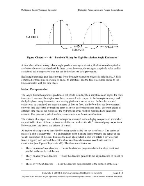
Figure Chapter 4 - -11: Parabola Fitting for High-Resolution Angle Estimation<br />
A time slice with no strong echoes might produce no angle estimates, if all measured amplitudes<br />
are below the detection threshold. In these cases, however, the strongest amplitude value and its<br />
associated beam angle are saved for use in the sidescan data processing.<br />
Each angle/amplitude pair that emerges from the angle estimation process is called a hit. A hit is<br />
composed <strong>of</strong> three pieces <strong>of</strong> data: its angle, its amplitude, and the time it occurred (equal to the<br />
time associated with the time slice).<br />
Motion Compensation<br />
The Angle Estimation process produces a list <strong>of</strong> hits including their amplitudes and angles for each<br />
time slice. However, the angles have been measured with respect to the hydrophone array, and<br />
the hydrophone array is mounted on a moving platform, a vessel at sea. Before the reported<br />
echoes can be translated into measurements <strong>of</strong> the sea floor, and before they can be compared<br />
between time slices (the hydrophone array will be in different positions and at different angles in<br />
different time slices), the motions <strong>of</strong> the hydrophone array must be measured and taken into<br />
account. This process is called motion compensation, or beam stabilization.<br />
The motions <strong>of</strong> a ship at sea and the hydrophone mounted to it are highly complex and somewhat<br />
unpredictable. Some <strong>of</strong> these motions are deliberate, such as the ship’s forward progress, or turns.<br />
However, most are due to the effects <strong>of</strong> waves.<br />
All motion <strong>of</strong> a ship can be described by using a point called the center <strong>of</strong> mass. The center <strong>of</strong><br />
mass <strong>of</strong> a ship is exactly that— it is an imaginary point in space that represents the center <strong>of</strong> the<br />
weight distribution <strong>of</strong> the ship. It is also the point about which a ship will rotate if any external<br />
force is applied to it. Around the center <strong>of</strong> mass a three dimensional coordinate system is<br />
constructed (see Figure Chapter 4 - -12). The three coordinates are:<br />
• The x, or acrosstrack direction – This is the direction perpendicular to the ships track and<br />
parallel to the surface <strong>of</strong> the sea.<br />
• The y, or alongtrack direction – This is the direction parallel to the ships direction <strong>of</strong> travel, or<br />
track.<br />
• The z, or vertical direction – This is the direction perpendicular to the surface <strong>of</strong> the sea.<br />
Copyright © 2000 L-3 Communications SeaBeam Instruments Page 4-13<br />
No portion <strong>of</strong> this document may be reproduced without the expressed written permission <strong>of</strong> L-3 Communications SeaBeam Instruments


