

Multibeam Sonar Theory of Operation
Multibeam Sonar Theory of Operation
Multibeam Sonar Theory of Operation

Create successful ePaper yourself
Turn your PDF publications into a flip-book with our unique Google optimized e-Paper software.
Introduction to <strong>Multibeam</strong> <strong>Sonar</strong>:<br />
Projector and Hydrophone Systems <strong>Multibeam</strong> <strong>Sonar</strong> <strong>Theory</strong> <strong>of</strong> <strong>Operation</strong><br />
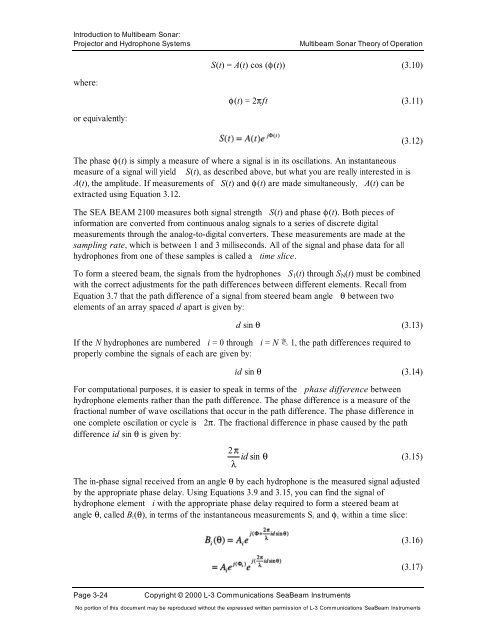
where:<br />
or equivalently:<br />
S(t) = A(t) cos (φ(t)) (3.10)<br />
φ(t) = 2πft (3.11)<br />
The phase φ(t) is simply a measure <strong>of</strong> where a signal is in its oscillations. An instantaneous<br />
measure <strong>of</strong> a signal will yield S(t), as described above, but what you are really interested in is<br />
A(t), the amplitude. If measurements <strong>of</strong> S(t) and φ(t) are made simultaneously, A(t) can be<br />
extracted using Equation 3.12.<br />
The SEA BEAM 2100 measures both signal strength S(t) and phase φ(t). Both pieces <strong>of</strong><br />
information are converted from continuous analog signals to a series <strong>of</strong> discrete digital<br />
measurements through the analog-to-digital converters. These measurements are made at the<br />
sampling rate, which is between 1 and 3 milliseconds. All <strong>of</strong> the signal and phase data for all<br />
hydrophones from one <strong>of</strong> these samples is called a time slice.<br />
Page 3-24 Copyright © 2000 L-3 Communications SeaBeam Instruments<br />
(3.12)<br />
To form a steered beam, the signals from the hydrophones S1(t) through SN(t) must be combined<br />
with the correct adjustments for the path differences between different elements. Recall from<br />
Equation 3.7 that the path difference <strong>of</strong> a signal from steered beam angle θ between two<br />
elements <strong>of</strong> an array spaced d apart is given by:<br />
d sin θ (3.13)<br />
If the N hydrophones are numbered i = 0 through i = N 1, the path differences required to<br />
properly combine the signals <strong>of</strong> each are given by:<br />
id sin θ (3.14)<br />
For computational purposes, it is easier to speak in terms <strong>of</strong> the phase difference between<br />
hydrophone elements rather than the path difference. The phase difference is a measure <strong>of</strong> the<br />
fractional number <strong>of</strong> wave oscillations that occur in the path difference. The phase difference in<br />
one complete oscillation or cycle is 2π. The fractional difference in phase caused by the path<br />
difference id sin θ is given by:<br />
2π<br />
id sin θ<br />
(3.15)<br />
λ<br />
The in-phase signal received from an angle θ by each hydrophone is the measured signal adjusted<br />
by the appropriate phase delay. Using Equations 3.9 and 3.15, you can find the signal <strong>of</strong><br />
hydrophone element i with the appropriate phase delay required to form a steered beam at<br />
angle θ, called Bi(θ), in terms <strong>of</strong> the instantaneous measurements Si and φi within a time slice:<br />
(3.16)<br />
(3.17)<br />
No portion <strong>of</strong> this document may be reproduced without the expressed written permission <strong>of</strong> L-3 Communications SeaBeam Instruments


