

Multibeam Sonar Theory of Operation
Multibeam Sonar Theory of Operation
Multibeam Sonar Theory of Operation

You also want an ePaper? Increase the reach of your titles
YUMPU automatically turns print PDFs into web optimized ePapers that Google loves.
Introduction to <strong>Multibeam</strong> <strong>Sonar</strong>:<br />
Projector and Hydrophone Systems <strong>Multibeam</strong> <strong>Sonar</strong> <strong>Theory</strong> <strong>of</strong> <strong>Operation</strong><br />
The SEA BEAM 2100 Projector and Hydrophone Arrays<br />
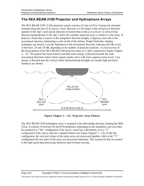
The SEA BEAM 2100 12 kHz projector system consists <strong>of</strong> a line <strong>of</strong> 10 to 14 projector elements<br />
mounted along the keel <strong>of</strong> its survey vessel. Because it is far longer in the alongtrack direction<br />
(parallel to the ship’s keel and its direction <strong>of</strong> motion) than in the acrosstrack or athwartship<br />
direction (perpendicular to the ship’s keel), the complete projector array is similar to a line array. It<br />
projects a beam that is narrow in the alongtrack direction (roughly 2 degrees), and wide in the<br />
acrosstrack direction, illuminating a wide swath <strong>of</strong> the bottom. Dolph-Chebyshev shading<br />
techniques are used to even the illumination in the acrosstrack direction, reducing side lobe levels<br />
to between -25 and -30 dB, depending on the number <strong>of</strong> projector elements. A cross-section <strong>of</strong><br />
the beam pattern <strong>of</strong> the SEA BEAM 2100 projector array at 12 kHz is depicted in Figure Chapter<br />
3 - -22. This pattern has been tailored such that more energy is directed towards the wide<br />
acrosstrack directions where return signals usually arrive with lower signal-to-noise levels. Less<br />
energy is directed near the vertical where backscattering strengths are usually high and travel<br />
distances are shorter.<br />
Figure Chapter 3 - -22: Projector Array Pattern<br />
The SEA BEAM 2100 hydrophone array is mounted in the athwartship direction, forming the Mills<br />
Cross. It consists <strong>of</strong> between 48 and 80 hydrophones, depending on the installation, and can either<br />
be mounted in a “flat” configuration if the survey vessel has a flat bottom, or in a “V”<br />
configuration if the survey ship has v-shaped bottom (see Figure Chapter 3 - -23). In the flat<br />
configuration, the received echoes <strong>of</strong> the entire array are processed together, while in the “V”<br />
configuration the two sides <strong>of</strong> the array are processed separately. The reasons for this are related<br />
to the high-speed data processing shortcuts used in beam steering.<br />
Page 3-22 Copyright © 2000 L-3 Communications SeaBeam Instruments<br />
No portion <strong>of</strong> this document may be reproduced without the expressed written permission <strong>of</strong> L-3 Communications SeaBeam Instruments


