Aesculap Spine Apfelbaum C1 - 2 Fixation - B. Braun Medical AS
Aesculap Spine Apfelbaum C1 - 2 Fixation - B. Braun Medical AS
Aesculap Spine Apfelbaum C1 - 2 Fixation - B. Braun Medical AS

You also want an ePaper? Increase the reach of your titles
YUMPU automatically turns print PDFs into web optimized ePapers that Google loves.
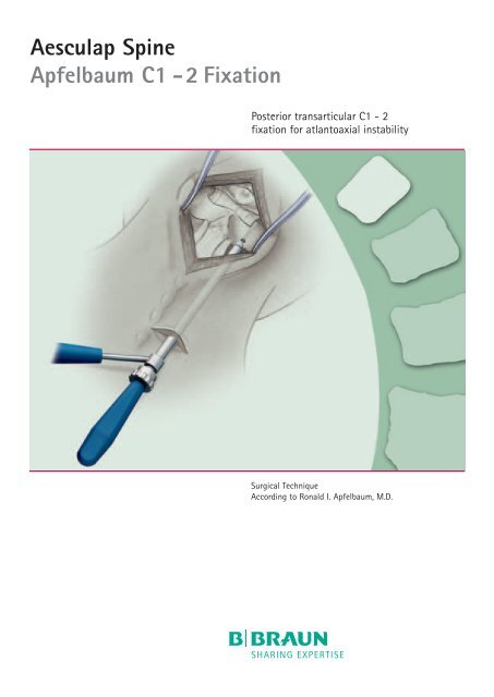
<strong>Aesculap</strong> <strong>Spine</strong><br />
<strong>Apfelbaum</strong> <strong>C1</strong> - 2 <strong>Fixation</strong><br />
Posterior transarticular <strong>C1</strong> - 2<br />
fixation for atlantoaxial instability<br />
Surgical Technique<br />
According to Ronald I. <strong>Apfelbaum</strong>, M.D.
2<br />
By<br />
Ronald I. <strong>Apfelbaum</strong>, M.D.<br />
Department of Neurosurgery<br />
University of Utah Health Sciences Center<br />
30 North 1900 East<br />
Salt Lake City, Utah 84132-2303<br />
USA<br />
Ronald <strong>Apfelbaum</strong>, M.D., is Professor<br />
of Neurosurgery at the University of Utah<br />
Health Sciences Center in Salt Lake City.<br />
In this publication, Dr. <strong>Apfelbaum</strong> describes<br />
a surgical technique for the treatment of<br />
Atlantoaxial Instability using the posterior<br />
approach with internal screw fixation.<br />
<strong>Aesculap</strong> instrumentation has been cleared<br />
by the FDA for spinal use.<br />
Warning: The screws described are not<br />
approved for screw attachment or fixation<br />
to the posterior elements (pedicles) of the<br />
cervical, thoracic or lumbar spine. Nor have<br />
the screws described in this surgical technique<br />
been cleared by the FDA.<br />
April 1993<br />
(Revised: February 1994/February 2003)
Introduction<br />
The atlantoaxial joint is a complex structure<br />
which facilitates head rotation on the neck. To<br />
achieve this, the joint surfaces are in a flat<br />
plane with no intervertebral disc or loose<br />
capsular ligaments. In addition, the other<br />
strong spinal ligaments such as the ligamentum<br />
flavum and the anterior and posterior longitudinal<br />
ligaments are attenuated or absent. 1 The<br />
strong transverse ligament (transverse portion<br />
of the cruciate ligament) is essential to retain<br />
the odontoid process of C2 in the anterior part<br />
of the ring of <strong>C1</strong>. This allows the desired rotation<br />
but prevents anterior-posterior translation<br />
which would jeopardize the spinal cord.<br />
Disruption or laxity of the transverse ligament<br />
results in atlantoaxial instability. This may<br />
occur due to trauma, local disease processes<br />
such as osteomyelitis, or due to local effects of<br />
systemic diseases such as rheumatoid arthritis.<br />
Atlantoaxial instability is also produced by<br />
trans-oral removal of the odontoid as might<br />
occur in treatment of basilar invagination with<br />
medullary compression or irreducible subluxation<br />
secondary to rheumatoid arthritis. Nonunion of<br />
the odontoid, either on a congenital or traumatic<br />
basis, negates the function of the transverse<br />
ligament and also results in atlantoaxial instability.<br />
Atlantoaxial instability often requires surgical<br />
stabilization, which is usually achieved by<br />
posterior fusion between the laminar arches of<br />
<strong>C1</strong> and C2. A number of surgical techniques<br />
have been advocated 2,3,4 to achieve this. All<br />
employ bone grafting and wiring in various<br />
configurations to produce the desired fusion. The<br />
normal mobility at <strong>C1</strong>-2, primarily in rotation,<br />
coupled with pathologic translation movements<br />
may explain the significant failure rates<br />
of the various <strong>C1</strong>-2 posterior fusion constructs.<br />
5 Elimination of motion, as well as placement<br />
of a bone graft under compression between the<br />
components to be fused, are considered key<br />
factors in obtaining successful fusion. External<br />
immobilization with a halo-vest or minerva<br />
jacket is often required and is recommended to<br />
restrict both normal and pathologic motion so<br />
that optimal bony fusion which produces<br />
stability is achieved. These devices, however,<br />
are not without their own significant medical<br />
and social morbidity.<br />
3
4<br />
Introduction<br />
In 1987, Magerl 6 reported a new technique of<br />
atlantoaxial stabilization which he pioneered in<br />
1976. This was a transarticular screw fixation<br />
approach (Figure 1) that offered immediate<br />
stability, eliminating the need for any external<br />
immobilization apparatus. This construct has<br />
proven very strong in biomechanical testing. 7,8,9<br />
Further experience with this technique in 161<br />
patients operated at four separate centers was<br />
reported by Grob et al. in 1991. 10 Stable fusion<br />
occured in all but one patient. Screw malpositions<br />
were infrequent (15%) and did not result<br />
in cord or vertebral artery injury, but the latter<br />
has occurred in our experience and resulted in<br />
a fatal brain stem infarction. For this reason,<br />
we now insist on a preoperative CT scan with<br />
parasagital reconstruction (see pages 12, 13).<br />
Additional reports emphasize that the procedure<br />
is both effective and safe if these precautions<br />
are followed. 11,12<br />
The technique involves standard exposure of<br />
the <strong>C1</strong>-2 area posteriorly and placement of<br />
screws bilaterally down the isthmus of C2 (pars<br />
inter-articularis) and across the <strong>C1</strong>-2 articulation<br />
to block movement and provide immediate<br />
internal fixation (Figure 2). Bone grafting in<br />
any of the usual techniques is then applied.<br />
Due to the low angle of approach needed to<br />
place these screws, Magerl´s original technique<br />
required exposure of the entire cervical spine<br />
and at times the upper thoracic vertebrae.<br />
However, by using an appropriate guide tube<br />
introduced through a small stab wound, a<br />
much smaller incision can be employed. Other<br />
than this special guide tube, the instruments<br />
function identically to the instruments of the<br />
odontoid screw fixation instrument set. Once<br />
this system has been mastered, the technique<br />
can therefore be applied to either operation. Fig. 2A
B C<br />
Fig. 2 A, B, C<br />
Radiographs of cadaveric atlas and fixation using Magerl´s technique to show location<br />
of the screws in 3 planes (From reference 14 used with permission of publisher).<br />
A<br />
Fig. 1 A, B<br />
AP and lateral illustrations from Magerl´s original text showing screw placement of transarticular screws at <strong>C1</strong>-2 to promote stable fusion.<br />
A posterior bone graft is then wired in place to achieve bony fusion (Fig. 1B) (From reference 6, used with permission of publisher).<br />
B<br />
5
6<br />
Surgical Technique<br />
The patient is positioned prone with the head<br />
supported in a pin head holder. Extending the<br />
lower cervical spine while flexing and posteriorly<br />
translating the skull and <strong>C1</strong> (”military posture”)<br />
will usually optimally reduce the <strong>C1</strong>-2<br />
dislocation while allowing the best trajectory to<br />
<strong>C1</strong>-2 (Figure 3 A). <strong>C1</strong>-2 position is optimized<br />
using a C-arm lateral fluoroscopic image.<br />
Extension of the lower cervical spine and maximal<br />
flexion at the occiput <strong>C1</strong>-2 region usually<br />
flattens the cervical lordosis and reduces<br />
atlantoaxial subluxation by posteriorly translating<br />
the atlas. After exposure of the posterior<br />
elements of <strong>C1</strong>-2, the lamina of C2 is dissected<br />
free of soft tissue to the C2-3 facet joints<br />
(Figure 3 B). Using a small angled curette, the<br />
superior edge of the lamina of C2 is followed<br />
laterally to identify the lateral edge of the<br />
spinal canal which is the medial side of the C2<br />
pedicle. This serves as the visual landmark for<br />
the medial limit of screw positioning. The dorsal<br />
surface of the isthmus can be followed anteriorly<br />
to the <strong>C1</strong>-2 articular joint by elevating the C2<br />
nerve root and associated venous plexus. This<br />
allows determination of the proper screw<br />
alignment in a dorsal ventral plane.<br />
An appropriate trajectory is visually determined<br />
by placing a drill or K-wire alongside the neck<br />
and aligning it fluoroscopically to the desired<br />
screw position. In this manner, an entrance site<br />
for the drill guide is established in the axial<br />
plane. Its sagittal coordinate is chosen to allow<br />
the screw to be placed in a strict parasagittal<br />
plane through the isthmus of C2 and crossing<br />
the <strong>C1</strong>-2 articulation into the lateral mass of<br />
<strong>C1</strong>. Note that the screw does not pass through<br />
the pedicle of C2, which would carry it into the<br />
C2 body, but rather dorsally through the isthmus<br />
(pars interarticularis) and across the <strong>C1</strong>-2<br />
articulation. The desired placement is 1-2 mm<br />
lateral to the lateral edge of the spinal canal<br />
(Figure 3 C).<br />
Medial Side of Pedicle Isthmus of C2 (Pars Interarticularis)<br />
C2 Nerve Root
8<br />
Surgical Technique<br />
Once the skin entrance site is determined<br />
(Figure 3 B), a 1.5 cm stab wound is made<br />
through the skin, subcutaneous tissue and dorsal<br />
fascia. It can be dilated with a hemostat and<br />
then the outer guide tube with its conical tipped<br />
obturator is worked through the tissue and into<br />
the surgical site.<br />
Its position can be adjusted, due to the flexibility<br />
of the soft tissue, to place it at the precise<br />
entrance site for the screw, which is just above<br />
the inferior edge of the C2 inferior articular<br />
process. The obturator is then removed (Figure<br />
5 A) and the inner drill guide placed (Figure 5 B).<br />
If desired, a sharp obturator is available to<br />
make a starter hole in the bone.<br />
A pilot hole is then drilled under fluoroscopic<br />
control through C2 into the lateral mass of <strong>C1</strong>,<br />
crossing the <strong>C1</strong>-2 articulation (Figures 6 and<br />
7). Standing back from the operative field by<br />
using a step stool helps eliminate parallax and<br />
allows more precise drill trajectory. On the lateral<br />
fluoroscopic image, this usually results in<br />
the drill pointing toward the anterior tubercle<br />
of <strong>C1</strong>. The depth of drilling is noted on the sliding<br />
sleeve of the inner drill guide (Figure 6 B).<br />
2<br />
1<br />
Fig. 5 A<br />
Fig. 5 A, B<br />
Guide tube in place as seen in sagittal (A) and<br />
dorsal (B) view. Once the guide tube/obturator<br />
assembly is worked through the soft tissue into<br />
the surgical site (5 A) the obturator is removed<br />
(Step 1, then 2) and replaced with the inner<br />
drill guide (5B).<br />
Fig. 5 B
Fig. 6 A<br />
A pilot hole is then drilled across the atlantoaxial<br />
joint and into the lateral mass of <strong>C1</strong>.<br />
Fig. 7<br />
Lateral fluoroscopic view of drilling process. The drill has crossed the<br />
<strong>C1</strong>-2 joint (arrow). A dissector placed on the pars helps orient the drill<br />
placement. The drill should be angled to pass just below this instrument.<br />
Fig. 6 B<br />
The depth can be read on the calibrated inner<br />
drill guide and will be accurate as long as the tip of<br />
the inner drill guide is in contact with the bone.<br />
9
10<br />
Surgical Technique<br />
The drill is removed as well as the inner drill<br />
guide (Figure 8 A). The hole is then tapped<br />
along its full length (Figure 8 B and 9 A). The<br />
tap cuts threads into the bone to prepare it for<br />
the screw. This instrument fits through the<br />
outer drill guide, as does the screw which is<br />
placed next (Figures 8 C, 8 D and 9 B).<br />
The procedure is then repeated on the other side.<br />
A Brooks, Gallie or Sonntag type posterior<br />
fusion is then placed (Figures 9 C, 9 D and 10)<br />
and the wounds closed. Subcutaneous stitches<br />
and sterile skin tape are usually sufficient for<br />
the trocar entry wounds. A cervical collar is<br />
usually not needed.<br />
Fig. 8 A<br />
1<br />
Fig. 8<br />
Once drilling is complete, the inner drill guide<br />
tube (A) should be removed (step 1, then 2).<br />
The pilot hole is then tapped (B) and the screw<br />
placed (C and D) through the outer guide tube.<br />
2<br />
Fig. 8 B Fig. 8 C<br />
Fig. 8 D
Fig. 9 A Tap in place<br />
Fig. 9 C<br />
Fig. 9 C, D<br />
Graft in place along with fixation screws.<br />
Fig. 9 B Screw being tightened<br />
Fig. 9 D<br />
Fig. 10<br />
Completed screw fixation<br />
and subsequent posterior<br />
bone grafting (Sonntag<br />
construct)<br />
11
12<br />
Discussion<br />
Due to the immediate stabilizing effects of the<br />
screws, patients can be quickly mobilized and<br />
hospital stays are usually brief. There appears<br />
to be less postoperative pain than expected,<br />
which may also be due to the immediate<br />
stability produced by this procedure.<br />
To avoid failure or injury to vital structures<br />
in this area, a thorough understanding of the<br />
anatomy and pathology is necessary.<br />
Appropriate preoperative studies can clarify<br />
this. We obtain thin section CT scans and<br />
reconstruct them parasagitally in the proposed<br />
plane of the fixation screw (See Figures 11 A, B<br />
and C). If the vertebral artery loops up and is in<br />
close proximity to the screw trajectory, the procedure<br />
is not attempted on that side. Also, if<br />
the disease process has significantly altered<br />
the normal anatomical relationships or<br />
destroyed the bone into which the screw will be<br />
placed, the procedure should not be attempted.<br />
These conditions on occasion will require that<br />
only one screw be placed. This is a weaker construct,<br />
so consideration should be given to the<br />
use of an external orthosis. Screw fixation<br />
should not be attempted if the fluoroscopic<br />
images are not satisfactory.<br />
Fig. 11 A<br />
Parasagittal reconstruction of CT scan through<br />
proposed screw path shows adequate bone to<br />
safely accept screw on patient´s right side.<br />
Fig. 11 A
Fig. 11 B<br />
Similar reconstruction on left side shows ectatic vertebral artery that has eroded into the bone (arrow)<br />
and might likely be injured by screw placement. Therefore, no screw was placed on that side.<br />
Fig. 11 C<br />
Coronal reconstruction confirms the erosion of the bone.<br />
13
14<br />
Discussion<br />
While we have used partially threaded screws<br />
in some of our initial cases, there is no lag<br />
effect expected. Therefore, fully threaded<br />
screws are preferred. We have employed this<br />
procedure in patients with incompetent transverse<br />
ligaments due to rheumatoid arthritis or<br />
trauma (Figure 12 A-F) or after transoral odontoid<br />
resection.<br />
Fig. 12 A<br />
Normal alignment in extension.<br />
Traumatic rupture of transverse ligament<br />
in a diving accident.<br />
Fig. 12 D<br />
T1 MRI shows blood at the site<br />
of ligament tear (arrows).
Fig. 12 B<br />
Widened predental space in flexation<br />
(between arrows).<br />
Fig. 12 E Fig. 12 F<br />
Fig. 12 E, F<br />
Postoperative radiographs of the screw fixation and Sonntag fusion.<br />
Fig. 12 C<br />
T2 MRI shows disruption of the transverse ligament on the left side (yellow arrow).<br />
The frayed end of the ligament (black) is surrounded by a halo of blood (white).<br />
Compare this with the intact ligament on the left (green arrows) which is in<br />
continuity with the bone (also black). 15<br />
15
16<br />
Discussion<br />
The technique has also been used to stabilize<br />
the <strong>C1</strong>-2 complex in cases of congenital ligamentous<br />
laxity (Larsen´s syndrome) (Figure 13)<br />
or os odontoidium. A number of our patients<br />
had failed prior <strong>C1</strong>-2 fusions.<br />
Fig. 13<br />
Patient with Larsen´s syndrom<br />
(congenital ligamentous laxity)<br />
and significant <strong>C1</strong>-2 instability.<br />
Fig. 13 A<br />
Good reduction and placement<br />
of Sonntag fusion.<br />
Fig. 13 C<br />
Revision with <strong>C1</strong>-2 screw fixation. Despite low<br />
screw trajectory dictated by bony anatomy, the<br />
screw crosses the <strong>C1</strong>-2 articulation (see arrows)<br />
and securely immobilizes this joint.<br />
Fig. 13 B<br />
Failure of fusion to unite after 5 months<br />
(in halo).<br />
Fig. 13 D<br />
Solid fusion 3 months later.
Indications/Contraindications<br />
An Overview<br />
INDICATIONS<br />
1 Disruption of transverse ligament:<br />
A) Trauma<br />
B) Local Infection<br />
C) Rheumatoid Arthritis<br />
2 After transoral odontoidectomy.<br />
3 Os odontoideum<br />
4 Chronic nonunions of odontoid.<br />
CONTRAINDICATIONS<br />
1 Ectasia of vertebral artery into the<br />
body of C2.<br />
2 Altered anatomy or bony destruction<br />
in the region of the proposed screw<br />
placement.<br />
3 Inadequate fluoroscopic images.<br />
17
18<br />
Conclusions<br />
This relatively simple procedure is facilitated<br />
by the instrumentation described in this manual.<br />
It allows us to offer our patients immediate<br />
stability and freedom from the necessity of<br />
using an external immobilizer while enhancing<br />
the success of the fusion. Fusion rates have<br />
been close to 100%. 6 Careful evaluation of the<br />
patient´s anatomy, with proper pre-operative<br />
imaging as well as attention to the technical<br />
details of the procedure, are necessary to perform<br />
it safely.
References<br />
1. White <strong>AS</strong>, Panjabi MM: Clinical biomechanics of the<br />
spine. J. B. Lippincott Company, Philadelphia, PA,<br />
pp65-70, pp198-203, 1978.<br />
2. Brooks AL, Jenkins EB: Atlanto-axial arthrodesis by<br />
the wedge compression method. J Bone Joint Surg.<br />
60A:279-283, 1978.<br />
3. Gallie WE: Fractures and dislocations of the cervical<br />
spine. Am J Surg. 46:495-499, 1939.<br />
4. Dickman CA, Sonntag VKH, Papadopoulos SM,<br />
Hadley MN: The interspinous method of posterior<br />
atlantoaxial arthrodesis. J Neurosurg 74:190-198,<br />
1991<br />
5. Fried LC: Atlantoaxial fracture dislocations. Failure<br />
of posterior <strong>C1</strong> to C2 fusion. J Bone Joint Surg<br />
55B:490-496.<br />
6. Magerl F, Seemann PS: Stable posterior fusion of the<br />
atlas and axis by transarticular screw fixation. In:<br />
Kehr P, Weidner A, eds. Cervical <strong>Spine</strong>. Wien, etc:<br />
Springer-Verlag, 1987:322-327.<br />
7. Ulrich C, Woersdoerfer O, Kalff R, Claes L, Wilke HJ:<br />
Biomechanics of fixation systems to the cervical<br />
spine. <strong>Spine</strong> 16:3S 55-59<br />
8. Grob D, Crisco JJ, Parjab MM, Wang P, Dvorak J:<br />
Biomechanical evaluation of four different posterior<br />
atlantoaxial fixation techniques. <strong>Spine</strong> 17:<br />
480-490,1992.<br />
9. Hanson PB, Montesano PX, Sharkey N,<br />
Rauschning W: Anatomic and biomechanical<br />
assessment of transarticular screw fixation for<br />
atlantoaxial instability. <strong>Spine</strong> 16: 1141-1145, 1991.<br />
10. Grob D, Jeanneret B, Aeb M, Markwalder T:<br />
Atlanto-axial fusion with transarticular screw<br />
fixation. J Bone Joint Surg. 73-B:972-976, 1991.<br />
11. Stillerman CB, Wilson JA: Atlantoaxial stabilization<br />
with posterior transarticular screw fixation:<br />
Technical description and report of 22 cases.<br />
Neurosurg. 32:6 948-955.<br />
12. Jeanneret B, Magerl F: Primary posterior fusion of<br />
<strong>C1</strong>/2 in odontoid fractures: Indications, techniques<br />
and results of transarticular screw fixation. J Spinal<br />
Disord 5: 464-475, 1992.<br />
13. <strong>Apfelbaum</strong> RI: Instrumentation for anterior screw<br />
fixation of odontoid fractures. <strong>Aesculap</strong> Scientific<br />
Information 24.<br />
<strong>Aesculap</strong> Ag, D-7200 Tuttlingen, Germany, 1992.<br />
14. Montesano PX, Juach EC, Anderson PA, et al.:<br />
Biomechanics of cervical spine internal fixation.<br />
<strong>Spine</strong> 16(3S), 1991.<br />
15. Dickman CA, Mamourian A, Sonntag VKH, Drayer BP:<br />
Magnetic resonance imaging of the transverse<br />
atlantal ligament for the evaluation of atlantoaxial<br />
instability. J Neurosurg 75:221-227, 1991.<br />
19
All rights reserved. Technical alterations are possible. This leaflet may be used<br />
for no other purposes than offering, buying and selling of our products.<br />
No part may be copied or reproduced in any form. In the case of misuse we<br />
retain the rights to recall our catalogues and pricelists and to take legal actions.<br />
Brochure No. O 235 02<br />
All it takes to operate.<br />
<strong>Aesculap</strong> AG & Co. KG<br />
Am <strong>Aesculap</strong>-Platz<br />
78532 Tuttlingen<br />
Phone +49 7461 95-0<br />
Fax +49 7461 95-2600<br />
www.aesculap.de<br />
0105/2/2
![PDF [0,06 MB] - B. Braun Medical AS](https://img.yumpu.com/19440664/1/184x260/pdf-006-mb-b-braun-medical-as.jpg?quality=85)
![PDF [1,93 MB] - B. Braun Medical AS](https://img.yumpu.com/18509534/1/184x260/pdf-193-mb-b-braun-medical-as.jpg?quality=85)
![PDF [0,03 MB] - B. Braun Medical AS](https://img.yumpu.com/18509477/1/184x260/pdf-003-mb-b-braun-medical-as.jpg?quality=85)
![PDF [0,40 MB] - B. Braun Medical AS](https://img.yumpu.com/18387519/1/190x135/pdf-040-mb-b-braun-medical-as.jpg?quality=85)