InnoDisk FiD 2.5â SATA25000
InnoDisk FiD 2.5â SATA25000
InnoDisk FiD 2.5â SATA25000

Create successful ePaper yourself
Turn your PDF publications into a flip-book with our unique Google optimized e-Paper software.
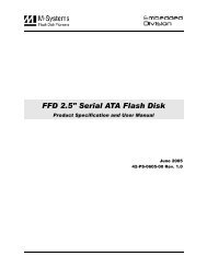
<strong>InnoDisk</strong> <strong>FiD</strong> 2.5” <strong>SATA25000</strong> for SLC Solution<br />
<strong>InnoDisk</strong> <strong>FiD</strong> 2.5” <strong>SATA25000</strong><br />
<strong>InnoDisk</strong> <strong>FiD</strong> 2.5” <strong>SATA25000</strong> for SLC Solution<br />
Datasheet<br />
Rev. 1.3<br />
1 Rev. 1.3 Datasheet, May..2011
Table of contents<br />
<strong>InnoDisk</strong> <strong>FiD</strong> 2.5” <strong>SATA25000</strong> for SLC Solution<br />
REVISION HISTORY ........................................................................................................................................... 4<br />
LIST OF TABLES ................................................................................................................................................ 5<br />
LIST OF FIGURES .............................................................................................................................................. 6<br />
1. PRODUCT OVERVIEW .............................................................................................................................. 7<br />
1.1 INTRODUCTION OF INNODISK FID 2.5” SATA 25000 ...................................................................................... 7<br />
1.2 PRODUCT VIEW ............................................................................................................................................ 7<br />
1.3 PRODUCT MODELS ...................................................................................................................................... 7<br />
1.4 SATA INTERFACE ......................................................................................................................................... 8<br />
1.5 2.5-INCH FORM FACTOR ................................................................................................................................ 8<br />
1.6 CAPACITY .................................................................................................................................................... 8<br />
2. THEORY OF OPERATION ......................................................................................................................... 9<br />
2.1 OVERVIEW ................................................................................................................................................... 9<br />
2.2 SATA II CONTROLLER .................................................................................................................................. 9<br />
2.3 ERROR DETECTION AND CORRECTION .......................................................................................................... 9<br />
2.4 WEAR-LEVELING ........................................................................................................................................ 10<br />
2.5 BAD BLOCKS MANAGEMENT ....................................................................................................................... 10<br />
3. INSTALLATION REQUIREMENTS .......................................................................................................... 11<br />
3.1 FID 2.5 SATA 25000 PIN DIRECTIONS........................................................................................................ 11<br />
3.2 ELECTRICAL CONNECTIONS FOR FID 2.5 SATA 25000 ................................................................................ 11<br />
3.3 FORM FACTOR ........................................................................................................................................... 11<br />
3.4 DEVICE DRIVE ............................................................................................................................................ 12<br />
4. SPECIFICATIONS .................................................................................................................................... 13<br />
4.1 CE AND FCC COMPATIBILITY ...................................................................................................................... 13<br />
4.2 ROHS COMPLIANCE .................................................................................................................................. 13<br />
4.3 ENVIRONMENTAL SPECIFICATIONS .............................................................................................................. 13<br />
4.3.1 Temperature Ranges ....................................................................................................................... 13<br />
4.3.2 Humidity ........................................................................................................................................... 13<br />
4.3.3 Shock and Vibration ......................................................................................................................... 13<br />
4.3.4 Mean Time between Failures (MTBF) ............................................................................................. 13<br />
4.4 ENDURANCE .............................................................................................................................................. 14<br />
4.5 TRANSFER MODE ....................................................................................................................................... 14<br />
4.6 PIN ASSIGNMENT ....................................................................................................................................... 14<br />
4.7 MECHANICAL DIMENSIONS .......................................................................................................................... 15<br />
2 Rev. 1.3 Datasheet, May..2011
<strong>InnoDisk</strong> <strong>FiD</strong> 2.5” <strong>SATA25000</strong> for SLC Solution<br />
4.8 ASSEMBLY WEIGHT ..................................................................................................................................... 15<br />
4.9 PERFORMANCE .......................................................................................................................................... 16<br />
4.10 SEEK TIME .............................................................................................................................................. 16<br />
4.11 HOT PLUG ............................................................................................................................................... 16<br />
4.12 NAND FLASH MEMORY ........................................................................................................................... 16<br />
4.13 ELECTRICAL SPECIFICATIONS ................................................................................................................... 16<br />
4.13.1 Power Requirement ....................................................................................................................... 16<br />
4.13.2 Power Consumption ....................................................................................................................... 17<br />
4.14 DEVICE PARAMETERS .............................................................................................................................. 17<br />
5. SUPPORTED ATA COMMANDS ............................................................................................................. 18<br />
5.1 SUPPORTED ATA COMMANDS ..................................................................................................................... 18<br />
6. PART NUMBER RULE ............................................................................................................................. 20<br />
3 Rev. 1.3 Datasheet, May..2011
REVISION HISTORY<br />
<strong>InnoDisk</strong> <strong>FiD</strong> 2.5” <strong>SATA25000</strong> for SLC Solution<br />
Revision Description Date<br />
Preliminary First Released 09/20/2010<br />
Rev. 1.0 1. Modify C.H.S<br />
2. Add power consumption<br />
Rev. 1.1 1. Wording correction<br />
2. Update performance<br />
1/12/2011<br />
1/14/2011<br />
Rev. 1.2 1. Add Trim description. 3/18/2011<br />
Rev. 1.3 1. Add Part Number Rule 5/19/2011<br />
4 Rev. 1.3 Datasheet, May..2011
List of Tables<br />
<strong>InnoDisk</strong> <strong>FiD</strong> 2.5” <strong>SATA25000</strong> for SLC Solution<br />
TABLE 1: SHOCK/VIBRATION TESTING FOR INNODISK FID 2.5” SATA 25000 ......................................................... 13<br />
TABLE 2: INNODISK FID 2.5” SATA 25000 MTBF................................................................................................ 14<br />
TABLE 3: INNODISK FID 2.5” SATA 25000 PIN ASSIGNMENT ................................................................................ 14<br />
TABLE 4: INNODISK FID 2.5” SATA 25000 POWER REQUIREMENT ....................................................................... 16<br />
TABLE 5: POWER CONSUMPTION .......................................................................................................................... 17<br />
TABLE 6: DEVICE PARAMETERS ............................................................................................................................ 17<br />
TABLE 7: ATA COMMANDS ................................................................................................................................... 18<br />
5 Rev. 1.3 Datasheet, May..2011
List of Figures<br />
<strong>InnoDisk</strong> <strong>FiD</strong> 2.5” <strong>SATA25000</strong> for SLC Solution<br />
FIGURE 1: INNODISK FID 2.5” SATA 25000 ........................................................................................................... 7<br />
FIGURE 2: INNODISK FID 2.5” SATA 25000 BLOCK DIAGRAM ................................................................................ 9<br />
FIGURE 3: SIGNAL SEGMENT AND POWER SEGMENT ............................................................................................. 11<br />
FIGURE 4: FID 2.5 SATA 25000 SLC MECHANICAL DIMENSIONS ........................................................................... 15<br />
6 Rev. 1.3 Datasheet, May..2011
1. Product Overview<br />
1.1 Introduction of <strong>InnoDisk</strong> <strong>FiD</strong> 2.5” SATA 25000<br />
<strong>InnoDisk</strong> <strong>FiD</strong> 2.5” <strong>SATA25000</strong> for SLC Solution<br />
<strong>InnoDisk</strong> <strong>FiD</strong> 2.5” SATA 25000 products provide high capacity flash memory Solid State Drive (SSD) that<br />
electrically complies with Serial ATA (SATA) standard. It supports SATA II standard (3.0GHz) with high<br />
performance. For SLC solution, sustain read is at 250 MB per second (max.), and sustain write is at 200 MB<br />
per second (max); Except sequential read/ write performance, <strong>InnoDisk</strong> <strong>FiD</strong> 2.5” SATA 25000 also enhances<br />
random data access for small files. Furthermore, <strong>InnoDisk</strong> <strong>FiD</strong> 2.5” SATA 25000 support trim for windows 7, it<br />
can improves performance when deleting files. It designed with standard 2.5-inch form factor, which can be<br />
used in laptop. <strong>InnoDisk</strong> <strong>FiD</strong> 2.5” SATA 25000 is designed for industrial field. The SSD have good<br />
performance, no latency time and small seek time. It effectively reduces the booting time of operation system<br />
and the power consumption is less than hard disk drive (HDD). <strong>InnoDisk</strong> <strong>FiD</strong> 2.5” SATA 25000 can work in<br />
harsh environment. The SSD is vibration resistance, and can work in lower or higher temperature than HDD.<br />
<strong>InnoDisk</strong> <strong>FiD</strong> 2.5” SATA 25000 complies with ATA protocol, no additional drives are required, and the SSD can<br />
be configured as a boot device or data storage device.<br />
1.2 Product View<br />
1.3 Product Models<br />
Figure 1: <strong>InnoDisk</strong> <strong>FiD</strong> 2.5” SATA 25000<br />
<strong>InnoDisk</strong> <strong>FiD</strong> 2.5” SATA 25000 is available in follow capacities.<br />
<strong>FiD</strong> 2.5” <strong>SATA25000</strong> 16GB (SLC)<br />
<strong>FiD</strong> 2.5” <strong>SATA25000</strong> 32GB (SLC)<br />
<strong>FiD</strong> 2.5” <strong>SATA25000</strong> 64GB (SLC)<br />
7 Rev. 1.3 Datasheet, May..2011
<strong>FiD</strong> 2.5” <strong>SATA25000</strong> 128GB (SLC)<br />
1.4 SATA Interface<br />
<strong>InnoDisk</strong> <strong>FiD</strong> 2.5” <strong>SATA25000</strong> for SLC Solution<br />
<strong>InnoDisk</strong> <strong>FiD</strong> 2.5” SATA 25000 support SATA II interface, and compliant with SATA I. SATA II interface can<br />
work with Serial Attached SCSI (SAS) host system, which is used in server computer. <strong>InnoDisk</strong> <strong>FiD</strong> 2.5” SATA<br />
25000 is compliant with Serial ATA Gen 1 and Gen 2 specification (Gen2 supports 1.5Gbps /3.0Gbps data rate).<br />
SATA connector uses a 7-pin signal segment and a 15-pin power segment.<br />
1.5 2.5-inch form factor<br />
Industry 2.5-inch standard form factor design with metal material case is easy for installation because 2.5-inch<br />
is a popular form factor in industrial field. 2.5-inch is most laptop’s hard disk’s form factor. <strong>InnoDisk</strong> <strong>FiD</strong> 2.5”<br />
SATA 25000 SSD can easy install in laptop. <strong>InnoDisk</strong> <strong>FiD</strong> 2.5” SATA 25000 has a compact design 99.88mm (L)<br />
x 69.63mm (W) x 9.3mm (H).<br />
1.6 Capacity<br />
<strong>InnoDisk</strong> <strong>FiD</strong> 2.5” <strong>SATA25000</strong> provides unformatted 16GB, 32GB, 64GB, and 128GB capacities within SLC<br />
flash ICs.<br />
8 Rev. 1.3 Datasheet, May..2011
2. Theory of operation<br />
2.1 Overview<br />
<strong>InnoDisk</strong> <strong>FiD</strong> 2.5” <strong>SATA25000</strong> for SLC Solution<br />
Figure 2 shows the operation of <strong>InnoDisk</strong> <strong>FiD</strong> 2.5” SATA 25000 from the system level, including the major<br />
hardware blocks.<br />
Host<br />
SATA<br />
Figure 2: <strong>InnoDisk</strong> <strong>FiD</strong> 2.5” SATA 25000 Block Diagram<br />
<strong>InnoDisk</strong> <strong>FiD</strong> 2.5” SATA 25000 integrates a SATA II controller and NAND flash memories. Communication with<br />
the host occurs through the host interface, using the standard ATA protocol. Communication with the flash<br />
device(s) occurs through the flash interface.<br />
2.2 SATA II Controller<br />
DRAM<br />
Buffer<br />
Buffer<br />
Management<br />
And Control<br />
ARM<br />
Micro P<br />
Load<br />
Code<br />
Circuit<br />
ROM RAM<br />
The SATA II controller is 3.0 Gbps (Gen. 2), and support hot-plug. The Serial ATA physical, link and transport<br />
layers are compliant with Serial ATA Gen 1 and Gen 2 specification (Gen 2 supports 1.5Gbps/3.0Gbps data<br />
rate). The controller has 8 channels for flash interface.<br />
The controller is equipped with 128KB of internal memory. The internal memory is used as an intermediate<br />
memory for storing data blocks during a wear-leveling procedure. A 32KB internal boot ROM includes basic<br />
routines for accessing the flash memories and for loading the main code into the internal memory.<br />
2.3 Error Detection and Correction<br />
Highly sophisticated Error Correction Code algorithms are implemented. The ECC unit consists of the Parity<br />
Unit (parity-byte generation) and the Syndrome Unit (syndrome-byte computation). This unit implements an<br />
algorithm that can correct 16 bits per 512 bytes in an ECC block. Code-byte generation during write operations,<br />
as well as error detection during read operation, is implemented on the fly without any speed penalties.<br />
9 Rev. 1.3 Datasheet, May..2011<br />
ECC<br />
Circuit<br />
Flash<br />
Sequence<br />
and<br />
Control<br />
Logic<br />
Flash<br />
Flash<br />
Flash<br />
Flash<br />
Flash<br />
Flash<br />
Flash<br />
Flash
2.4 Wear-Leveling<br />
<strong>InnoDisk</strong> <strong>FiD</strong> 2.5” <strong>SATA25000</strong> for SLC Solution<br />
Flash memory can be erased within a limited number of times. This number is called the erase cycle limit or<br />
write endurance limit and is defined by the flash array vendor. The erase cycle limit applies to each individual<br />
erase block in the flash device.<br />
<strong>InnoDisk</strong> <strong>FiD</strong> 2.5” SATA 25000 uses a static wear-leveling algorithm to ensure that consecutive writes of a<br />
specific sector are not written physically to the same page/block in the flash. This spreads flash media usage<br />
evenly across all pages, thereby extending flash lifetime.<br />
2.5 Bad Blocks Management<br />
Bad Blocks are blocks that contain one or more invalid bits whose reliability are not guaranteed. The Bad<br />
Blocks may be presented while the SSD is shipped, or may develop during the life time of the SSD. When the<br />
Bad Blocks is detected, it will be flagged, and not be used anymore. The SSD implement Bad Blocks<br />
management, Bad Blocks replacement, Error Correct Code to avoid data error occurred. The functions will be<br />
enabled automatically to transfer data from Bad Blocks to spare blocks, and correct error bit.<br />
10 Rev. 1.3 Datasheet, May..2011
3. Installation Requirements<br />
3.1 <strong>FiD</strong> 2.5 SATA 25000 Pin Directions<br />
Figure 3: Signal Segment and Power Segment<br />
3.2 Electrical Connections for <strong>FiD</strong> 2.5 SATA 25000<br />
<strong>InnoDisk</strong> <strong>FiD</strong> 2.5” <strong>SATA25000</strong> for SLC Solution<br />
A Serial ATA device may be either directly connected to a host or connected to a host through a cable. For<br />
connection via cable, the cable should be no longer than 1meter. The SATA interface has a separate connector<br />
for the power supply. Please refer to the pin description for further details.<br />
3.3 Form Factor<br />
Please prepare following things:<br />
Screw driver.<br />
Four M3 screws.<br />
SATA single cable (7-pin, Maximum length l meter).<br />
SATA power cable (15-pin).<br />
Please turn off your computer, and open your computer’s case. Find one of available 2.5-inch slot, and plug<br />
the SSD in. To use the screws fix the SSD. Plug in the SATA single cable, and power cable.<br />
Please boot the installation Operation System from CD-ROM, and install Operation System into SSD.<br />
11 Rev. 1.3 Datasheet, May..2011
3.4 Device drive<br />
<strong>InnoDisk</strong> <strong>FiD</strong> 2.5” <strong>SATA25000</strong> for SLC Solution<br />
Figure 4: <strong>FiD</strong> 2.5” SATA 25000 Mechanical Screw Hole<br />
No additional device drives are required. The <strong>InnoDisk</strong> <strong>FiD</strong> 2.5” SATA 25000 can be configured as a boot<br />
device.<br />
12 Rev. 1.3 Datasheet, May..2011
4. Specifications<br />
4.1 CE and FCC Compatibility<br />
<strong>InnoDisk</strong> <strong>FiD</strong> 2.5” SATA 25000 conforms to CE and FCC requirements.<br />
4.2 RoHS Compliance<br />
<strong>InnoDisk</strong> <strong>FiD</strong> 2.5” SATA 25000 is fully compliant with RoHS directive.<br />
4.3 Environmental Specifications<br />
4.3.1 Temperature Ranges<br />
Operating Temperature Range:<br />
- Standard Grade: 0°C to +70°C<br />
- Industrial Grade: -40°C to +85°C<br />
Storage Temperature Range:<br />
- Standard Grade: -55°C to +95°C<br />
- Industrial Grade: -55°C to +95°C<br />
4.3.2 Humidity<br />
Relative Humidity: 10-95%, non-condensing<br />
4.3.3 Shock and Vibration<br />
<strong>InnoDisk</strong> <strong>FiD</strong> 2.5” <strong>SATA25000</strong> for SLC Solution<br />
Table 1: Shock/Vibration Testing for <strong>InnoDisk</strong> <strong>FiD</strong> 2.5” SATA 25000<br />
Reliability Test Conditions Reference Standards<br />
Vibration 7 Hz to 2K Hz, 20G, 3 axes IEC 68-2-6<br />
Mechanical Shock Duration: 0.5ms, 1500 G, 3 axes IEC 68-2-27<br />
4.3.4 Mean Time between Failures (MTBF)<br />
Table 2 summarizes the MTBF prediction results for various <strong>InnoDisk</strong> <strong>FiD</strong> 2.5” SATA 25000 configurations. The<br />
analysis was performed using a RAM Commander failure rate prediction.<br />
‧ Failure Rate: The total number of failures within an item population, divided by the total number of life<br />
units expended by that population, during a particular measurement interval under stated condition.<br />
‧ Mean Time between Failures (MTBF): A basic measure of reliability for repairable items: The mean<br />
number of life units during which all parts of the item perform within their specified limits, during a particular<br />
13 Rev. 1.3 Datasheet, May..2011
measurement interval under stated conditions.<br />
4.4 Endurance<br />
Table 2: <strong>InnoDisk</strong> <strong>FiD</strong> 2.5” SATA 25000 MTBF<br />
<strong>InnoDisk</strong> <strong>FiD</strong> 2.5” <strong>SATA25000</strong> for SLC Solution<br />
Product Condition MTBF (Hours)<br />
<strong>InnoDisk</strong> <strong>FiD</strong> 2.5” SATA 25000 Telcordia SR-332 GB, 25°C >4,000,000<br />
Read Cycles: Unlimited Read Cycles.<br />
Data Retention: 10 years.<br />
Wear-Leveling Algorithm: Support.<br />
Bad Blocks Management: Support<br />
Error Correct Code: Support<br />
4.5 Transfer Mode<br />
<strong>InnoDisk</strong> <strong>FiD</strong> 2.5” SATA 25000 support following transfer mode:<br />
PIO Mode 0~4<br />
Ultra DMA 0~6<br />
Serial ATA I 1.5Gbps<br />
Serial ATA II 3.0Gbps<br />
4.6 Pin Assignment<br />
<strong>InnoDisk</strong> <strong>FiD</strong> 2.5” SATA 25000 uses a standard SATA pin-out. See Table 3 for <strong>InnoDisk</strong> <strong>FiD</strong> 2.5” SATA 25000<br />
pin assignments.<br />
Table 3: <strong>InnoDisk</strong> <strong>FiD</strong> 2.5” SATA 25000 Pin Assignment<br />
Name Type Description<br />
S1 GND NA<br />
S2 A+<br />
S3 A-<br />
S4 GND NA<br />
S5 B-<br />
S6 B+<br />
S7 GND NA<br />
Differential Signal Pair A<br />
Differential Signal Pair B<br />
Key and Spacing separate signal and power segments<br />
P1 NC NA<br />
P2 NC NA<br />
P3 NC NA<br />
P4 GND NA<br />
P5 GND NA<br />
14 Rev. 1.3 Datasheet, May..2011
P6 GND NA<br />
P7 V5 5V Power, Pre-Charge<br />
P8 V5 5V Power<br />
P9 V5 5V Power<br />
P10 GND NA<br />
<strong>InnoDisk</strong> <strong>FiD</strong> 2.5” <strong>SATA25000</strong> for SLC Solution<br />
P11 DAS/DSS Device Activity Signal / Disable Staggered Spinup<br />
P12 GND NA<br />
P13 NC NA<br />
P14 NC NA<br />
P15 NC NA<br />
4.7 Mechanical Dimensions<br />
4.8 Assembly weight<br />
Figure 4: <strong>FiD</strong> 2.5 SATA 25000 SLC mechanical dimensions<br />
An <strong>InnoDisk</strong> <strong>FiD</strong> 2.5” SATA 25000 within SLC flash ICs, 16GB’s weight is 90 grams approx. If the capacity is<br />
different, the flash chip’s weight needs to be added. However, the total weight of SSD will be less than 95<br />
grams.<br />
15 Rev. 1.3 Datasheet, May..2011
4.9 Performance<br />
Burst Transfer Rate: 3.0 Gbps<br />
Sustained Read : 250MB/sec (max.)<br />
Sustained Write : 200MB/sec (max.)<br />
4.10 Seek Time<br />
<strong>InnoDisk</strong> <strong>FiD</strong> 2.5” <strong>SATA25000</strong> for SLC Solution<br />
<strong>InnoDisk</strong> <strong>FiD</strong> 2.5” SATA 25000 is not a magnetic rotating design. There is no seek or rotational latency<br />
required.<br />
4.11 Hot Plug<br />
The SSD support hot plug function and can be removed or plugged-in during operation. User has to avoid hot<br />
plugging the SSD which is configured as boot device and installed operation system.<br />
Surprise hot plug : The insertion of a SATA device into a backplane (combine signal and power) that has<br />
power present. The device powers up and initiates an OOB sequence.<br />
Surprise hot removal: The removal of a SATA device from a powered backplane, without first being placed in a<br />
quiescent state.<br />
4.12 NAND Flash Memory<br />
<strong>InnoDisk</strong> <strong>FiD</strong> 2.5” SATA 25000 uses Single Level Cell (SLC) NAND flash memory, which is non-volatility, high<br />
reliability and high speed memory storage. There are only two statuses 0 or 1 of one cell. Read or Write data to<br />
flash memory for SSD is control by micro processor.<br />
4.13 Electrical Specifications<br />
4.13.1 Power Requirement<br />
Table 4: <strong>InnoDisk</strong> <strong>FiD</strong> 2.5” SATA 25000 Power Requirement<br />
Item Symbol Rating Unit<br />
Input voltage VIN +5DC +- 5% 500mA (max.) V<br />
16 Rev. 1.3 Datasheet, May..2011
4.13.2 Power Consumption<br />
4.14 Device Parameters<br />
Table 5: Power Consumption<br />
Mode Power Consumption (mA)<br />
Read 450<br />
Write 560<br />
Idle 200<br />
<strong>FiD</strong> 2.5 SATA 25000 device parameters are shown in Table 6.<br />
Table 6: Device parameters<br />
<strong>InnoDisk</strong> <strong>FiD</strong> 2.5” <strong>SATA25000</strong> for SLC Solution<br />
Capacity LBA Cylinders Heads Sectors User capacity<br />
16GB 29323728 16383 16 63 14318.23<br />
32GB 62533296 16383 16 63 30533.84<br />
64GB 125045424 16383 16 63 61057.34<br />
128GB 250069680 16383 16 63 122104.34<br />
17 Rev. 1.3 Datasheet, May..2011
5. Supported ATA Commands<br />
5.1 Supported ATA Commands<br />
<strong>InnoDisk</strong> <strong>FiD</strong> 2.5” SATA 25000 supports the commands listed in Table 7.<br />
Command Name Code<br />
Table 7: ATA Commands<br />
<strong>InnoDisk</strong> <strong>FiD</strong> 2.5” <strong>SATA25000</strong> for SLC Solution<br />
PARAMETERS USED<br />
SC SN CY DR HD FT<br />
CHECK POWER MODE E5h X X X O X X<br />
EXECUTE DIAGNOSTICS 90h X X X O X X<br />
FLUSH CACHE E7h X X X O O X<br />
IDENTIFY DEVICE ECh X X X O X X<br />
IDLE E3h O X X O X X<br />
IDLE IMMEDIATE E1h X X X O X X<br />
INITIALIZE DEVICE<br />
PARAMETERS<br />
91h O X X O O X<br />
READ DMA C8h or C9h O O O O O X<br />
READ MULTIPLE C4h O O O O O X<br />
READ SECTOR(S) 20h or 21h O O O O O X<br />
READ VERIFY SECTOR(S) 40h or 41h O O O O O X<br />
RECALIBRATE 10h X X X O X X<br />
SECURITY DISABLE<br />
PASSWORD<br />
F6h X X X O X X<br />
SECURITY ERASE PREPARE F3h X X X O X X<br />
SECURITY ERASE UNIT F4h X X X O X X<br />
SECURITY FREEZE LOCK F5h X X X O X X<br />
SECURITY SET PASSWORD F1h X X X O X X<br />
SECURITY UNLOCK F2h X X X O X X<br />
SEEK 7xh X X O O O X<br />
SET FEATURES EFh O X X O X O<br />
SET MULTIPLE MODE C6h O X X O X X<br />
SLEEP E6h X X X O X X<br />
SMART B0h X X O O X O<br />
STANDBY E2h X X X O X X<br />
STANDBY IMMEDIATE E0h X X X O X X<br />
WRITE DMA CAh or CBh O O O O O X<br />
WRITE MULTIPLE C5h O O O O O X<br />
WRITE SECTOR(S) 30h or 31h O O O O O X<br />
18 Rev. 1.3 Datasheet, May..2011
Note:<br />
O = Valid,<br />
X = Don't care<br />
SC = Sector Count Register<br />
SN = Sector Number Register<br />
CY = Cylinder Low/High Register<br />
DR = DEVICE SELECT Bit (DEVICE/HEAD Register Bit 4)<br />
HD = HEAD SELECT Bit (DEVICE/HEAD Register Bit 3-0)<br />
FT = Features Register<br />
<strong>InnoDisk</strong> <strong>FiD</strong> 2.5” <strong>SATA25000</strong> for SLC Solution<br />
19 Rev. 1.3 Datasheet, May..2011
6. Part Number Rule<br />
CODE<br />
Description Disk<br />
<strong>InnoDisk</strong> <strong>FiD</strong> 2.5” <strong>SATA25000</strong> for SLC Solution<br />
1 2 3 4 5 6 7 8 9 10 11 12 13 14 15 16 17 18 19 20<br />
D 2 S N - A 2 8 J 2 0 A C 1 E S<br />
2.5” SATA<br />
25000<br />
- Capacity Category FW Operation<br />
Temp.<br />
Definition<br />
Internal<br />
Control<br />
Code 1 st (Disk) Code 13 th (Operation Temperature)<br />
D : Disk C: Standard Grade (0℃~ +70℃)<br />
Code 2 nd ~ 4 th (Form Factor) W: Industrial Grade (-40℃~ +85℃)<br />
2SN: 2.5” <strong>FiD</strong> SATA 25000 K: Standard Grade with coating<br />
Code 6 th ~8 th (Capacity) T: Industrial Grade with coating<br />
16G: 16GB Code 14 th (Internal control)<br />
32G: 32GB Code 15 th (Channel of data transfer)<br />
64G: 64GB E: Eight Channels<br />
A28: 128GB Code 16 th (Flash Type)<br />
Code 9 th ~11 th (Series) S: Samsung SLC<br />
J20: 2.5” <strong>FiD</strong> SATA 25000 T: Micron SLC<br />
Code 12 th (Firmware version)<br />
A: Standard F/W version<br />
20 Rev. 1.3 Datasheet, May..2011<br />
T<br />
CH. Flash - Customized<br />
Code