EverGreen Plus 2.5â SATA SSD
EverGreen Plus 2.5â SATA SSD
EverGreen Plus 2.5â SATA SSD

You also want an ePaper? Increase the reach of your titles
YUMPU automatically turns print PDFs into web optimized ePapers that Google loves.
<strong>EverGreen</strong> <strong>Plus</strong> 2.5” <strong>SATA</strong> <strong>SSD</strong><br />
<strong>EverGreen</strong> <strong>Plus</strong> 2.5” <strong>SATA</strong> <strong>SSD</strong><br />
InnoDisk <strong>EverGreen</strong> <strong>Plus</strong> 2.5” <strong>SATA</strong> <strong>SSD</strong><br />
Datasheet<br />
1 Rev. 0.3 Datasheet, May. 2011<br />
Rev. 0.3
Table of contents<br />
<strong>EverGreen</strong> <strong>Plus</strong> 2.5” <strong>SATA</strong> <strong>SSD</strong><br />
REVISION HISTORY ........................................................................................................................................... 4<br />
LIST OF TABLES ................................................................................................................................................ 5<br />
LIST OF FIGURES .............................................................................................................................................. 6<br />
1. PRODUCT OVERVIEW .............................................................................................................................. 7<br />
1.1 INTRODUCTION OF EVERGREEN / EVERGREEN PLUS* <strong>SATA</strong> <strong>SSD</strong> .................................................................. 7<br />
1.2 PRODUCT VIEW ............................................................................................................................................ 7<br />
1.3 PRODUCT MODELS ...................................................................................................................................... 7<br />
1.3 <strong>SATA</strong> INTERFACE ......................................................................................................................................... 8<br />
1.4 CAPACITIES.................................................................................................................................................. 8<br />
1.5 2.5-INCH FORM FACTOR ................................................................................................................................ 8<br />
2. THEORY OF OPERATION ......................................................................................................................... 9<br />
2.1 OVERVIEW ................................................................................................................................................... 9<br />
2.2 <strong>SATA</strong> II CONTROLLER .................................................................................................................................. 9<br />
2.3 ERROR DETECTION AND CORRECTION .......................................................................................................... 9<br />
2.4 WEAR-LEVELING ........................................................................................................................................ 10<br />
2.5 BAD BLOCKS MANAGEMENT ....................................................................................................................... 10<br />
2.6 POWER CYCLING PROTECTION AND CIRCUIT DESIGN ..................................................................................... 10<br />
3. INSTALLATION REQUIREMENTS .......................................................................................................... 11<br />
3.1 EVERGREEN PLUS 2.5” <strong>SATA</strong> <strong>SSD</strong> PIN DIRECTIONS .................................................................................. 11<br />
3.2 ELECTRICAL CONNECTIONS FOR EVERGREEN PLUS 2.5” <strong>SATA</strong> <strong>SSD</strong> ........................................................... 11<br />
3.3 FORM FACTOR ........................................................................................................................................... 11<br />
3.4 DEVICE DRIVE ............................................................................................................................................ 12<br />
4. SPECIFICATIONS .................................................................................................................................... 13<br />
4.1 CE AND FCC COMPATIBILITY ...................................................................................................................... 13<br />
4.2 ROHS COMPLIANCE .................................................................................................................................. 13<br />
4.3 ENVIRONMENTAL SPECIFICATIONS .............................................................................................................. 13<br />
4.3.1 Temperature Ranges ....................................................................................................................... 13<br />
4.3.2 Humidity ........................................................................................................................................... 13<br />
4.3.3 Shock and Vibration ......................................................................................................................... 13<br />
4.3.4 Mean Time between Failures (MTBF) ............................................................................................. 13<br />
4.4 ENDURANCE .............................................................................................................................................. 14<br />
4.5 TRANSFER MODE ....................................................................................................................................... 14<br />
4.6 PIN ASSIGNMENT ....................................................................................................................................... 14<br />
2 Rev. 0.3 Datasheet, May. 2011
<strong>EverGreen</strong> <strong>Plus</strong> 2.5” <strong>SATA</strong> <strong>SSD</strong><br />
4.7 MECHANICAL DIMENSIONS .......................................................................................................................... 15<br />
4.8 ASSEMBLY WEIGHT ..................................................................................................................................... 15<br />
4.9 PERFORMANCE .......................................................................................................................................... 16<br />
4.10 IOPS ...................................................................................................................................................... 16<br />
4.11 SEEK TIME ............................................................................................................................................... 16<br />
4.12 HOT PLUG ............................................................................................................................................... 16<br />
4.13 NAND FLASH MEMORY ........................................................................................................................... 16<br />
4.14 ELECTRICAL SPECIFICATIONS ................................................................................................................... 17<br />
4.14.1 Power Requirement ....................................................................................................................... 17<br />
4.14.2 Power Consumption ....................................................................................................................... 17<br />
4.15 DEVICE PARAMETERS .............................................................................................................................. 17<br />
5. SUPPORTED ATA COMMANDS ............................................................................................................. 18<br />
5.1 SUPPORTED ATA COMMANDS ..................................................................................................................... 18<br />
6. PART NUMBER RULE ............................................................................................................................. 20<br />
3 Rev. 0.3 Datasheet, May. 2011
REVISION HISTORY<br />
Revision Description Date<br />
<strong>EverGreen</strong> <strong>Plus</strong> 2.5” <strong>SATA</strong> <strong>SSD</strong><br />
Preliminary First Released 12/30/2010<br />
Rev.0.1 1. Add PN rule 1/24/2011<br />
Rev.0.2 1. Add section of Power cycling protection and circuit<br />
design<br />
2. Add IOPS info.<br />
2/24/2011<br />
Rev.0.3 1. Modify Par Number Rule and available capacity info. 5/23/2011<br />
4 Rev. 0.3 Datasheet, May. 2011
List of Tables<br />
<strong>EverGreen</strong> <strong>Plus</strong> 2.5” <strong>SATA</strong> <strong>SSD</strong><br />
TABLE 1: SHOCK/VIBRATION TESTING FOR EVERGREEN PLUS 2.5” <strong>SATA</strong> <strong>SSD</strong> .................................................... 13<br />
TABLE 2: EVERGREEN PLUS 2.5” <strong>SATA</strong> <strong>SSD</strong> MTBF ........................................................................................... 14<br />
TABLE 3: EVERGREEN PLUS 2.5” <strong>SATA</strong> <strong>SSD</strong> PIN ASSIGNMENT ........................................................................... 14<br />
TABLE 4: EVERGREEN PLUS 2.5” <strong>SATA</strong> <strong>SSD</strong> POWER REQUIREMENT ................................................................... 17<br />
TABLE 5: POWER CONSUMPTION .......................................................................................................................... 17<br />
TABLE 6: DEVICE PARAMETERS ............................................................................................................................ 17<br />
TABLE 7: ATA COMMANDS ................................................................................................................................... 18<br />
5 Rev. 0.3 Datasheet, May. 2011
List of Figures<br />
<strong>EverGreen</strong> <strong>Plus</strong> 2.5” <strong>SATA</strong> <strong>SSD</strong><br />
FIGURE 1: EVERGREEN PLUS 2.5” <strong>SATA</strong> <strong>SSD</strong> ....................................................................................................... 7<br />
FIGURE 2: EVERGREEN PLUS 2.5” <strong>SATA</strong> <strong>SSD</strong> BLOCK DIAGRAM ............................................................................ 9<br />
FIGURE 3: SIGNAL SEGMENT AND POWER SEGMENT ............................................................................................. 11<br />
FIGURE 4: EVERGREEN PLUS 2.5” <strong>SATA</strong> <strong>SSD</strong> MECHANICAL DIMENSIONS............................................................. 15<br />
6 Rev. 0.3 Datasheet, May. 2011
1. Product Overview<br />
1.1 Introduction of <strong>EverGreen</strong> / <strong>EverGreen</strong> <strong>Plus</strong>* <strong>SATA</strong> <strong>SSD</strong><br />
<strong>EverGreen</strong> <strong>Plus</strong> 2.5” <strong>SATA</strong> <strong>SSD</strong><br />
InnoDisk Evergreen series provides a totally brand new highly cost-effective <strong>SSD</strong> solution with good<br />
performance and longer lifespan. Customer can pay much less but embrace longer life and performance than<br />
current SLC flash IC based <strong>SSD</strong> solutions. Evergreen Series <strong>SSD</strong>s is a perfect substitute for traditional HDD,<br />
which are applied with an evolved L 2 Wear Leveling Architecture, and significantly improves <strong>SSD</strong> random<br />
data transfer rate and lifespan.<br />
<strong>EverGreen</strong> <strong>Plus</strong> 2.5” <strong>SATA</strong> <strong>SSD</strong> provides high capacity flash memory Solid State Drive (<strong>SSD</strong>) that electrically<br />
complies with Serial ATA (<strong>SATA</strong>) standard, and supports <strong>SATA</strong> II standard (3.0GHz) with high performance. It<br />
has good performance; no latency time and small seek time. It effectively reduces the booting time of operation<br />
system and the power consumption is less than hard disk drive (HDD).<br />
* L 2 Architecture provides two different versions to enhance sequential performance (<strong>EverGreen</strong>) and<br />
extended lifespan (<strong>EverGreen</strong> <strong>Plus</strong>) respectively.<br />
1.2 Product View<br />
1.3 Product Models<br />
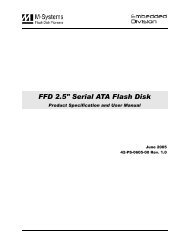
Figure 1: <strong>EverGreen</strong> <strong>Plus</strong> 2.5” <strong>SATA</strong> <strong>SSD</strong><br />
<strong>EverGreen</strong> <strong>Plus</strong> 2.5” <strong>SATA</strong> <strong>SSD</strong> is available in follow capacities.<br />
<strong>EverGreen</strong> <strong>Plus</strong> 2.5” <strong>SATA</strong> <strong>SSD</strong> 8GB <strong>EverGreen</strong> <strong>Plus</strong> 2.5” <strong>SATA</strong> <strong>SSD</strong> 16GB<br />
<strong>EverGreen</strong> <strong>Plus</strong> 2.5” <strong>SATA</strong> <strong>SSD</strong> 32GB <strong>EverGreen</strong> <strong>Plus</strong> 2.5” <strong>SATA</strong> <strong>SSD</strong> 64GB<br />
<strong>EverGreen</strong> <strong>Plus</strong> 2.5” <strong>SATA</strong> <strong>SSD</strong> 128GB <strong>EverGreen</strong> <strong>Plus</strong> 2.5” <strong>SATA</strong> <strong>SSD</strong> 256GB<br />
7 Rev. 0.3 Datasheet, May. 2011
1.3 <strong>SATA</strong> Interface<br />
<strong>EverGreen</strong> <strong>Plus</strong> 2.5” <strong>SATA</strong> <strong>SSD</strong><br />
<strong>EverGreen</strong> <strong>Plus</strong> 2.5” <strong>SATA</strong> <strong>SSD</strong> support <strong>SATA</strong> II interface, and backward compliant with <strong>SATA</strong> I Spec.<br />
1.4 Capacities<br />
<strong>EverGreen</strong> <strong>Plus</strong> 2.5” <strong>SATA</strong> <strong>SSD</strong> is available in five capacities: 6GB, 12GB, 25GB, 50GB, and 100GB. The<br />
drives ship with 8GB, 16GB, 32GB, 64GB, 128GB and 256GB of MLC NAND on them by default. Roughly 20%<br />
of the drive capacity is designated as spare area for L 2 Architecture and bad block replacement.<br />
1.5 2.5-inch form factor<br />
<strong>EverGreen</strong> <strong>Plus</strong> 2.5” <strong>SATA</strong> <strong>SSD</strong> has a compact design 99.88mm (L) x 69.63mm (W) x 9.3mm (H) with metal<br />
material case, and is easy for installation.<br />
8 Rev. 0.3 Datasheet, May. 2011
2. Theory of operation<br />
2.1 Overview<br />
<strong>EverGreen</strong> <strong>Plus</strong> 2.5” <strong>SATA</strong> <strong>SSD</strong><br />
Figure 2 shows the operation of <strong>EverGreen</strong> <strong>Plus</strong> 2.5” <strong>SATA</strong> <strong>SSD</strong> from the system level, including the major<br />
hardware blocks.<br />
Host<br />
<strong>SATA</strong><br />
Figure 2: <strong>EverGreen</strong> <strong>Plus</strong> 2.5” <strong>SATA</strong> <strong>SSD</strong> Block Diagram<br />
<strong>EverGreen</strong> <strong>Plus</strong> 2.5” <strong>SATA</strong> <strong>SSD</strong> integrates a <strong>SATA</strong> II controller, external DRAM, and NAND flash memories.<br />
Communication with the host occurs through the host interface, using the standard ATA protocol.<br />
Communication with the flash device(s) occurs through the flash interface.<br />
2.2 <strong>SATA</strong> II Controller<br />
DRAM<br />
Buffer<br />
Buffer<br />
Management<br />
And Control<br />
ARM<br />
Micro P<br />
Load<br />
Code<br />
Circuit<br />
ROM RAM<br />
The <strong>SATA</strong> II controller is 3.0 Gbps (Gen. 2), and support hot-plug. The Serial ATA physical, link and transport<br />
layers are compliant with Serial ATA Gen 1 and Gen 2 specification (Gen 2 supports 1.5Gbps/3.0Gbps data<br />
rate). The controller has 8 channels for flash interface.<br />
The controller is equipped with 128KB of internal memory. The internal memory is used as an intermediate<br />
memory for storing data blocks during a wear-leveling procedure. A 32KB internal boot ROM includes basic<br />
routines for accessing the flash memories and for loading the main code into the internal memory.<br />
2.3 Error Detection and Correction<br />
Highly sophisticated Error Correction Code algorithms are implemented. The ECC unit consists of the Parity<br />
Unit (parity-byte generation) and the Syndrome Unit (syndrome-byte computation). This unit implements an<br />
algorithm that can correct 16 bits per 512 bytes in an ECC block. Code-byte generation during write operations,<br />
as well as error detection during read operation, is implemented on the fly without any speed penalties.<br />
9 Rev. 0.3 Datasheet, May. 2011<br />
ECC<br />
Circuit<br />
Flash<br />
Sequence<br />
and<br />
Control<br />
Logic<br />
Flash<br />
Flash<br />
Flash<br />
Flash<br />
Flash<br />
Flash<br />
Flash<br />
Flash
2.4 Wear-Leveling<br />
<strong>EverGreen</strong> <strong>Plus</strong> 2.5” <strong>SATA</strong> <strong>SSD</strong><br />
Flash memory can be erased within a limited number of times. This number is called the erase cycle limit or<br />
write endurance limit and is defined by the flash array vendor. The erase cycle limit applies to each individual<br />
erase block in the flash device.<br />
<strong>EverGreen</strong> <strong>Plus</strong> 2.5” <strong>SATA</strong> <strong>SSD</strong> uses a static wear-leveling algorithm to ensure that consecutive writes of a<br />
specific sector are not written physically to the same page/block in the flash. This spreads flash media usage<br />
evenly across all pages, thereby extending flash lifetime.<br />
2.5 Bad Blocks Management<br />
Bad Blocks are blocks that contain one or more invalid bits whose reliability are not guaranteed. The Bad<br />
Blocks may be presented while the <strong>SSD</strong> is shipped, or may develop during the life time of the <strong>SSD</strong>. When the<br />
Bad Blocks is detected, it will be flagged, and not be used anymore. The <strong>SSD</strong> implement Bad Blocks<br />
management, Bad Blocks replacement, Error Correct Code to avoid data error occurred. The functions will be<br />
enabled automatically to transfer data from Bad Blocks to spare blocks, and correct error bit.<br />
2.6 Power cycling protection and circuit design<br />
<strong>EverGreen</strong> <strong>Plus</strong> is designed with a unique circuit to prevent abnormal power failure. With its real time power<br />
management function, and advanced L 2 Architecture, <strong>EverGreen</strong> <strong>Plus</strong> can effectively prevent power cycling<br />
issue, as well as keep data completely be written into disk.<br />
Moreover, with built in iCell* function, <strong>EverGreen</strong> <strong>Plus</strong> can not only keep power stable, but also ensure all data<br />
can be written into disk, once suddenly power shot down,<br />
*iCell is optional function of <strong>EverGreen</strong> <strong>Plus</strong>.<br />
10 Rev. 0.3 Datasheet, May. 2011
3. Installation Requirements<br />
3.1 <strong>EverGreen</strong> <strong>Plus</strong> 2.5” <strong>SATA</strong> <strong>SSD</strong> Pin Directions<br />
Figure 3: Signal Segment and Power Segment<br />
3.2 Electrical Connections for <strong>EverGreen</strong> <strong>Plus</strong> 2.5” <strong>SATA</strong> <strong>SSD</strong><br />
<strong>EverGreen</strong> <strong>Plus</strong> 2.5” <strong>SATA</strong> <strong>SSD</strong><br />
A Serial ATA device may be either directly connected to a host or connected to a host through a cable. For<br />
connection via cable, the cable should be no longer than 1meter. The <strong>SATA</strong> interface has a separate connector<br />
for the power supply. Please refer to the pin description for further details.<br />
3.3 Form Factor<br />
Please prepare following things:<br />
Screw driver.<br />
Four M3 screws.<br />
<strong>SATA</strong> single cable (7-pin, Maximum length l meter).<br />
<strong>SATA</strong> power cable (15-pin).<br />
Please turn off your computer, and open your computer’s case. Find one of available 2.5-inch slot, and plug<br />
the <strong>SSD</strong> in. To use the screws fix the <strong>SSD</strong>. Plug in the <strong>SATA</strong> single cable, and power cable.<br />
Please boot the installation Operation System from CD-ROM, and install Operation System into <strong>SSD</strong>.<br />
11 Rev. 0.3 Datasheet, May. 2011
3.4 Device drive<br />
Figure 4: <strong>EverGreen</strong> <strong>Plus</strong> 2.5” <strong>SATA</strong> <strong>SSD</strong> Mechanical Screw Hole<br />
<strong>EverGreen</strong> <strong>Plus</strong> 2.5” <strong>SATA</strong> <strong>SSD</strong><br />
No additional device drives are required. The <strong>EverGreen</strong> <strong>Plus</strong> 2.5” <strong>SATA</strong> <strong>SSD</strong> can be configured as a boot<br />
device.<br />
12 Rev. 0.3 Datasheet, May. 2011
4. Specifications<br />
4.1 CE and FCC Compatibility<br />
<strong>EverGreen</strong> <strong>Plus</strong> 2.5” <strong>SATA</strong> <strong>SSD</strong> conforms to CE and FCC requirements.<br />
4.2 RoHS Compliance<br />
<strong>EverGreen</strong> <strong>Plus</strong> 2.5” <strong>SATA</strong> <strong>SSD</strong> is fully compliant with RoHS directive.<br />
4.3 Environmental Specifications<br />
4.3.1 Temperature Ranges<br />
Operating Temperature Range:<br />
- Standard Grade: 0°C to +70°C<br />
Storage Temperature Range:<br />
- Standard Grade: -55°C to +95°C<br />
4.3.2 Humidity<br />
Relative Humidity: 10-95%, non-condensing<br />
4.3.3 Shock and Vibration<br />
Table 1: Shock/Vibration Testing for <strong>EverGreen</strong> <strong>Plus</strong> 2.5” <strong>SATA</strong> <strong>SSD</strong><br />
<strong>EverGreen</strong> <strong>Plus</strong> 2.5” <strong>SATA</strong> <strong>SSD</strong><br />
Reliability Test Conditions Reference Standards<br />
Vibration 7 Hz to 2K Hz, 20G, 3 axes IEC 68-2-6<br />
Mechanical Shock Duration: 0.5ms, 1500 G, 3 axes IEC 68-2-27<br />
4.3.4 Mean Time between Failures (MTBF)<br />
Table 2 summarizes the MTBF prediction results for various <strong>EverGreen</strong> <strong>Plus</strong> 2.5” <strong>SATA</strong> <strong>SSD</strong> configurations.<br />
The analysis was performed using a RAM Commander failure rate prediction.<br />
‧ Failure Rate: The total number of failures within an item population, divided by the total number of life<br />
units expended by that population, during a particular measurement interval under stated condition.<br />
‧ Mean Time between Failures (MTBF): A basic measure of reliability for repairable items: The mean<br />
‧<br />
number of life units during which all parts of the item perform within their specified limits, during a particular<br />
measurement interval under stated conditions.<br />
13 Rev. 0.3 Datasheet, May. 2011
4.4 Endurance<br />
Table 2: <strong>EverGreen</strong> <strong>Plus</strong> 2.5” <strong>SATA</strong> <strong>SSD</strong> MTBF<br />
Product Condition MTBF (Hours)<br />
<strong>EverGreen</strong> <strong>Plus</strong> 2.5” <strong>SATA</strong> <strong>SSD</strong> Telcordia SR-332 GB, 25°C >4,000,000<br />
Read Cycles: Unlimited Read Cycles.<br />
Data Retention: 10 years.<br />
Wear-Leveling Algorithm: Support.<br />
Bad Blocks Management: Support<br />
Error Correct Code: Support<br />
4.5 Transfer Mode<br />
<strong>EverGreen</strong> <strong>Plus</strong> 2.5” <strong>SATA</strong> <strong>SSD</strong> support following transfer mode:<br />
Ultra DMA 0~6<br />
Serial ATA I 1.5Gbps<br />
Serial ATA II 3.0Gbps<br />
4.6 Pin Assignment<br />
<strong>EverGreen</strong> <strong>Plus</strong> 2.5” <strong>SATA</strong> <strong>SSD</strong><br />
<strong>EverGreen</strong> <strong>Plus</strong> 2.5” <strong>SATA</strong> <strong>SSD</strong> uses a standard <strong>SATA</strong> pin-out. See Table 3 for <strong>EverGreen</strong> <strong>Plus</strong> 2.5” <strong>SATA</strong><br />
<strong>SSD</strong> pin assignments.<br />
Table 3: <strong>EverGreen</strong> <strong>Plus</strong> 2.5” <strong>SATA</strong> <strong>SSD</strong> Pin Assignment<br />
Name Type Description<br />
S1 GND NA<br />
S2 A+<br />
S3 A-<br />
S4 GND NA<br />
S5 B-<br />
S6 B+<br />
S7 GND NA<br />
Differential Signal Pair A<br />
Differential Signal Pair B<br />
Key and Spacing separate signal and power segments<br />
P1 NC NC<br />
P2 NC NC<br />
P3 NC NC<br />
P4 GND NA<br />
P5 GND NA<br />
14 Rev. 0.3 Datasheet, May. 2011
P6 GND NA<br />
P7 V5 5V Power, Pre-Charge<br />
P8 V5 5V Power<br />
P9 V5 5V Power<br />
P10 GND NA<br />
P11 DAS/DSS Device Activity Signal / Disable Staggered Spinup<br />
P12 GND NA<br />
P13 NC NC<br />
P14 NC NC<br />
P15 NC NC<br />
4.7 Mechanical Dimensions<br />
4.8 Assembly weight<br />
Figure 4: <strong>EverGreen</strong> <strong>Plus</strong> 2.5” <strong>SATA</strong> <strong>SSD</strong> mechanical dimensions<br />
<strong>EverGreen</strong> <strong>Plus</strong> 2.5” <strong>SATA</strong> <strong>SSD</strong><br />
An <strong>EverGreen</strong> <strong>Plus</strong> 2.5” <strong>SATA</strong> <strong>SSD</strong> within flash ICs, 32GB’s weight is 90 grams approx. If the capacity is<br />
different, the flash chip’s weight needs to be added. However, the total weight of <strong>SSD</strong> will be less than 95<br />
grams.<br />
15 Rev. 0.3 Datasheet, May. 2011
4.9 Performance<br />
Burst Transfer Rate: 3.0 Gbps<br />
32GB, 64GB, 128GB and 256GB<br />
Sustained Read : 180MB/sec (max.)<br />
Sustained Write : 55MB/sec (max.)<br />
16GB<br />
Sustained Read : 100MB/sec (max.)<br />
Sustained Write : 20MB/sec (max.)<br />
8GB<br />
Sustained Read : 60MB/sec (max.)<br />
Sustained Write : 10MB/sec (max.)<br />
4.10 IOPS<br />
Random 4 KB Read: up to 3,500 IOPS (min.)<br />
Random 4 KB Write: up to 650 IOPS (min.)<br />
4.11 Seek Time<br />
<strong>EverGreen</strong> <strong>Plus</strong> 2.5” <strong>SATA</strong> <strong>SSD</strong><br />
<strong>EverGreen</strong> <strong>Plus</strong> 2.5” <strong>SATA</strong> <strong>SSD</strong> is not a magnetic rotating design. There is no seek or rotational latency<br />
required.<br />
4.12 Hot Plug<br />
The <strong>SSD</strong> support hot plug function and can be removed or plugged-in during operation. User has to avoid hot<br />
plugging the <strong>SSD</strong> which is configured as boot device and installed operation system.<br />
Surprise hot plug : The insertion of a <strong>SATA</strong> device into a backplane (combine signal and power) that has<br />
power present. The device powers up and initiates an OOB sequence.<br />
Surprise hot removal: The removal of a <strong>SATA</strong> device from a powered backplane, without first being placed in a<br />
quiescent state.<br />
4.13 NAND Flash Memory<br />
<strong>EverGreen</strong> <strong>Plus</strong> 2.5” <strong>SATA</strong> <strong>SSD</strong> uses Multi Level Cell (MLC) NAND flash memory, with InnoDisk L 2 Wear<br />
Leveling Architecture Firmware.<br />
16 Rev. 0.3 Datasheet, May. 2011
4.14 Electrical Specifications<br />
4.14.1 Power Requirement<br />
Table 4: <strong>EverGreen</strong> <strong>Plus</strong> 2.5” <strong>SATA</strong> <strong>SSD</strong> Power Requirement<br />
Item Symbol Rating Unit<br />
Input voltage VIN +5DC +- 5% 500mA (max.) V<br />
4.14.2 Power Consumption<br />
4.15 Device Parameters<br />
Table 5: Power Consumption<br />
Mode Power Consumption<br />
Read 460<br />
Write 580<br />
Idle 160<br />
<strong>EverGreen</strong> <strong>Plus</strong> 2.5” <strong>SATA</strong> <strong>SSD</strong><br />
<strong>EverGreen</strong> <strong>Plus</strong> 2.5” <strong>SATA</strong> <strong>SSD</strong> is designed with InnoDisk L 2 Wear Leveling Architecture, and is available in<br />
five capacities: 6GB, 12GB, 25GB, 50GB, 100GB and 200GB. The drives ship with 8GB, 16GB, 32GB, 64GB,<br />
128GB and 256GB of MLC NAND on them by default. Roughly 20% of the drive capacity is designated as<br />
spare area for wear leveling and bad block replacement.<br />
<strong>EverGreen</strong> <strong>Plus</strong> 2.5” <strong>SATA</strong> <strong>SSD</strong> device parameters are shown in Table 6.<br />
Table 6: Device parameters<br />
Capacity LBA Cylinders Heads Sectors<br />
User capacity<br />
(MB)<br />
8GB 13107200 16383 16 63 6400<br />
16GB 26214400 16383 16 63 12800<br />
32GB 52428800 16383 16 63 25600<br />
64GB 104857600 16383 16 63 51200<br />
128GB 209715200 16383 16 63 102400<br />
256GB 419430400 16383 16 63 204800<br />
17 Rev. 0.3 Datasheet, May. 2011
5. Supported ATA Commands<br />
5.1 Supported ATA Commands<br />
<strong>EverGreen</strong> <strong>Plus</strong> 2.5” <strong>SATA</strong> <strong>SSD</strong> supports the commands listed in Table 7.<br />
Command Name Code<br />
Table 7: ATA Commands<br />
<strong>EverGreen</strong> <strong>Plus</strong> 2.5” <strong>SATA</strong> <strong>SSD</strong><br />
PARAMETERS USED<br />
SC SN CY DR HD FT<br />
CHECK POWER MODE E5h X X X O X X<br />
EXECUTE DIAGNOSTICS 90h X X X O X X<br />
FLUSH CACHE E7h X X X O O X<br />
IDENTIFY DEVICE ECh X X X O X X<br />
IDLE E3h O X X O X X<br />
IDLE IMMEDIATE E1h X X X O X X<br />
INITIALIZE DEVICE<br />
PARAMETERS<br />
91h O X X O O X<br />
READ DMA C8h or C9h O O O O O X<br />
READ MULTIPLE C4h O O O O O X<br />
READ SECTOR(S) 20h or 21h O O O O O X<br />
READ VERIFY SECTOR(S) 40h or 41h O O O O O X<br />
RECALIBRATE 10h X X X O X X<br />
SECURITY DISABLE<br />
PASSWORD<br />
F6h X X X O X X<br />
SECURITY ERASE PREPARE F3h X X X O X X<br />
SECURITY ERASE UNIT F4h X X X O X X<br />
SECURITY FREEZE LOCK F5h X X X O X X<br />
SECURITY SET PASSWORD F1h X X X O X X<br />
SECURITY UNLOCK F2h X X X O X X<br />
SEEK 7xh X X O O O X<br />
SET FEATURES EFh O X X O X O<br />
SET MULTIPLE MODE C6h O X X O X X<br />
SLEEP E6h X X X O X X<br />
SMART B0h X X O O X O<br />
STANDBY E2h X X X O X X<br />
STANDBY IMMEDIATE E0h X X X O X X<br />
WRITE DMA CAh or CBh O O O O O X<br />
WRITE MULTIPLE C5h O O O O O X<br />
WRITE SECTOR(S) 30h or 31h O O O O O X<br />
18 Rev. 0.3 Datasheet, May. 2011
Note:<br />
O = Valid,<br />
X = Don't care<br />
SC = Sector Count Register<br />
SN = Sector Number Register<br />
CY = Cylinder Low/High Register<br />
DR = DEVICE SELECT Bit (DEVICE/HEAD Register Bit 4)<br />
HD = HEAD SELECT Bit (DEVICE/HEAD Register Bit 3-0)<br />
FT = Features Register<br />
<strong>EverGreen</strong> <strong>Plus</strong> 2.5” <strong>SATA</strong> <strong>SSD</strong><br />
19 Rev. 0.3 Datasheet, May. 2011
6. Part number rule<br />
CODE<br />
Description Disk<br />
<strong>EverGreen</strong> <strong>Plus</strong> 2.5” <strong>SATA</strong> <strong>SSD</strong><br />
1 2 3 4 5 6 7 8 9 10 11 12 13 14 15 16 17 18 19 20<br />
D 2 S L - A 2 8 J 2 0 A C 1 E N<br />
2.5”<br />
<strong>EverGreen</strong><br />
<strong>Plus</strong> <strong>SSD</strong><br />
- Capacity Category FW Operation<br />
Temp.<br />
Definition<br />
Internal<br />
Control<br />
Ch. Flash - Customized<br />
Code<br />
Code 1 st (Disk) Code 12 th (Firmware Version)<br />
D: Flash Disk A: Standard F/W version<br />
Code 2 nd ~ 4 th (Product Model) Code 13 th (Operation Temperature)<br />
2SL: 2.5” <strong>EverGreen</strong> <strong>Plus</strong> <strong>SSD</strong> C: Standard Grade (0℃ ~ +70 ℃)<br />
Code 6 th ~8 th (Capacity) Code 14 th (Internal Control Code)<br />
08G: 8GB 1: 1 st PCB version, default setting<br />
16G: 16GB<br />
32G: 32GB Code 15 th (Channel of Data Transfer)<br />
64G: 64GB D: Dual Channels<br />
A28: 128GB Q: Four Channels<br />
B56: 256GB E: Eight Channels<br />
Code 9 th ~ 11 th (Series) Code 16 th (Flash Type)<br />
J20: <strong>EverGreen</strong> <strong>Plus</strong> series N: Micron MLC<br />
20 Rev. 0.3 Datasheet, May. 2011