

Boring and Milling Table - Home Model Engine Machinist
Boring and Milling Table - Home Model Engine Machinist
Boring and Milling Table - Home Model Engine Machinist

You also want an ePaper? Increase the reach of your titles
YUMPU automatically turns print PDFs into web optimized ePapers that Google loves.
<strong>Boring</strong> <strong>and</strong> <strong>Milling</strong> <strong>Table</strong><br />
ADDS TO UTILITY OF YOUR LATHE<br />
By C. W. WOODSON<br />
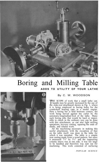
HE SCOPE of work that a small lathe can<br />
T h<strong>and</strong>le may be greatly increased by the use of<br />
the slide-rest attachment shown in Fig. 1, where<br />
it is being employed in boring holes for the<br />
crankshaft bearing caps in a model engine.<br />
Here a boring bar is held between centers, the<br />
work being moved against the cutter by the<br />
automatic longitudinal feed of the lathe. Many<br />
such boring jobs that would be hard or impossible<br />
to chuck in the ordinary way can be done<br />
with this attachment, as can also light milling<br />
operations, keyway cutting, squaring the ends of<br />
shafts, <strong>and</strong> similar work.<br />
All the machining necessary in making this<br />
useful attachment, with the exception of that<br />
on the table itself, was done in the lathe for<br />
which it was intended. The table is a simple<br />
iron casting made from a wood pattern, but since<br />
it measured 7¼" by 5½" <strong>and</strong> the supporting<br />
column sleeve was at one side, it was too large<br />
to be h<strong>and</strong>led <strong>and</strong> therefore was sent out for<br />
machining. This work consisted of surfacing<br />
POPULAR SCIENCE
the top <strong>and</strong> boring the hole for the sleeve.<br />
If the table is made smaller than this, it can<br />
probably be turned <strong>and</strong> bored on the faceplate<br />
of the lathe itself, but the larger size<br />
will be more useful.<br />
After the machining had been done, the<br />
holes for clamping work to the table were<br />
drilled as in Fig. 2, <strong>and</strong> tapped ¼"-20. They<br />
may be laid out to suit individual requirements,<br />
or the table can be left blank <strong>and</strong><br />
holes drilled as necessary to suit the job in<br />
h<strong>and</strong>.<br />
Turning the clamping screw from solid<br />
steel (Fig. 3) was a simple lathe job. The<br />
screw was threaded 5/16"-18, <strong>and</strong> the hole<br />
for it drilled in the table casting before the<br />
clamping slot was cut with a hack saw.<br />
One half of the hole was tapped to fit, the<br />
other half drilled out to clear the threads.<br />
This completed the work on the table, which<br />
is shown with the clamping screw in place in<br />
Fig. 4.<br />
Cold-rolled steel was turned <strong>and</strong> bored to<br />
the dimensions shown for the base of the<br />
supporting column (Fig. 5). The bottom<br />
of this piece was made to fit the lathe, so<br />
that it can be clamped to the cross slide in<br />
place of the compound rest. Reversed in the<br />
lathe <strong>and</strong> supported by the steady rest, as in<br />
Fig. 6, the column was left-h<strong>and</strong> threaded<br />
for the adjusting screw, a specially ground<br />
cutter bit being used. The keyway was<br />
made with a Woodruff keyway cutter while<br />
the work was held in a milling attachment.<br />
A brass tube of a size to be a nice sliding<br />
fit on the column was squared on both ends<br />
while held in the three-jaw chuck <strong>and</strong> supported<br />
by the steady rest, then drilled for<br />
screws to hold the key fast. The end cap<br />
was turned from steel to a snap fit in the<br />
sleeve, then reversed in the chuck as in<br />
Fig. 7 for threading the hole for the adjusting-screw<br />
guide. Drilling <strong>and</strong> tapping the<br />
holes for the two retaining screws, which<br />
was done with the end cap snapped into<br />
place in the sleeve, completed the supporting<br />
column.<br />
The adjusting screw was made from ½"<br />
steel rod, centerdrilled at each end <strong>and</strong><br />
turned between centers (Fig. 8). The lefth<strong>and</strong><br />
Acme threads, 10 to the inch, were cut<br />
to fit those in the steel column. The work<br />
NOVEMBER, 189
Threading the end cap, turning the adjusting screw, the complete set of parts for the screw, <strong>and</strong> the screw<br />
as it appears when assembled. Below, drawings of the table, the clamping screw, <strong>and</strong> the assembled column<br />
190<br />
7¼<br />
.625 1½ 3"<br />
18 TPI.<br />
TAP 5/16 - 18<br />
TAP ¼ - 2O<br />
2½<br />
2½<br />
SAW SLOT<br />
2½<br />
CLAMPING SCREW<br />
.187<br />
2½<br />
1½<br />
DRILL .312<br />
.125<br />
.625<br />
½<br />
5½<br />
2"<br />
MACHINE<br />
TOP ONLY<br />
1" .625<br />
.375<br />
SLEEVE<br />
KEY<br />
KEYWAY<br />
.250<br />
1"<br />
STEEL<br />
PILLAR<br />
. 094<br />
MAKE TO<br />
FIT LATHE<br />
18 TPI<br />
.625<br />
2¼ ID<br />
½ - 10<br />
LEFT-HAND<br />
ACME THREAD<br />
1"<br />
1.375<br />
END<br />
CAP<br />
5 ½<br />
4"<br />
.563<br />
POPULAR SCIENCE
The drawings below give the dimensions to be used<br />
in machining the adjusting screw <strong>and</strong> its parts<br />
24 T.P.I.<br />
8"<br />
1¾"<br />
.375<br />
½"<br />
WOODRUFF<br />
KEY FOR<br />
BALL CRANK<br />
18 T.P.I.<br />
.219<br />
.500<br />
.875<br />
.812<br />
.375<br />
1" 1"<br />
1"<br />
1"<br />
.375<br />
.625<br />
Left, the completed boring <strong>and</strong> milling table. Above, the base of<br />
the column <strong>and</strong> the sleeve unit with the adjusting screw in place<br />
TAP 3/8 - 24<br />
.187<br />
.687<br />
.875<br />
1½"<br />
TAPER<br />
DRIVE<br />
FIT<br />
.625<br />
was then reversed, <strong>and</strong> 3/8"-24 threads were<br />
cut on the other end, after which the keyway<br />
for the ball-crank h<strong>and</strong>le was cut in<br />
exactly the same manner as that in the<br />
column itself.<br />
All the parts of the adjusting screw are<br />
shown in Fig. 9. Although the ball-crank<br />
h<strong>and</strong>le can be made on the lathe according<br />
to the dimensions given, one from a discarded<br />
machine may be equally suitable.<br />
Figure 10 shows these parts assembled on<br />
the screw, <strong>and</strong> Fig. 11 the steel column <strong>and</strong><br />
the sleeve. The finished accessory is illustrated<br />
in Fig. 12, ready for work.<br />
NOVEMBER, 1941 191

