Create successful ePaper yourself
Turn your PDF publications into a flip-book with our unique Google optimized e-Paper software.
ASSEMBLINGSWITCHTO STAND<br />
If you purchased one of the motors recommended for use<br />
with your lathe, you received a switch and cord set connected<br />
to the motor. Assemble the switch to the stand as follows:<br />
1. IMPORTANT: When assembling the switch to the<br />
stand, MAKE SURE the motor power cord is not connected<br />
to the power source.<br />
2. Remove outer hex nut (A) Fig. 11, from the switch<br />
stem. Leave shakeproof washer (B) and inside hex nut (C)<br />
on switch stem. IMPORTANT: The proper grounding of the<br />
switch to prevent shock hazard, depends on the use of the<br />
shake proof lockwasher (B) in the manner shown.<br />
3. Insert switch stem through hole in front of top shelf<br />
of stand making sure keyway in switch stem in on the bottom.<br />
4. Place switch bracket (D) Fig. 12, on switch stem with<br />
key in switch bracket engaged with keyway in switch stem and<br />
fasten in place with hex nut removed in STEP 2.<br />
5. IMPORTANT: We suggestthat when the lathe is not in<br />
use, the switch be locked in the "OFF" position using a<br />
padlock. Catalog No. 49-031 Padlock is available as an accessory.<br />
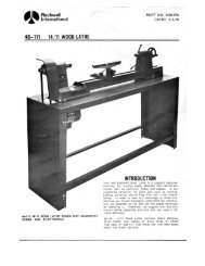
ASSEMBLINGBELTANDALIGNING<br />
MOTORPULLEYTO SPINDLEPULLEY<br />
1. Lift up motor and assemble belt to motor pulley, as<br />
shown in Fig. 13.<br />
2. Make sure motor pulley (A) Fig. 13, is aligned to spindle<br />
pulley (B). If necessary loosen set screw and slide motor<br />
pulley (A) in or out on motor shaft. NOTE: If additional<br />
adjustment is required the motor can be moved on the hinge<br />
bracket.<br />
6<br />
-<br />
Fig. 11<br />
Fig. 12<br />
Fig. 13<br />
B<br />
A<br />
.