
You also want an ePaper? Increase the reach of your titles
YUMPU automatically turns print PDFs into web optimized ePapers that Google loves.
c<br />
.<br />
I;,on<br />
nua,1<br />
I<br />
I<br />
i<br />
J<br />
j<br />
f<br />
I<br />
i<br />
1 I.<br />
I<br />
11 II<br />
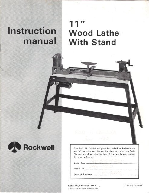
<strong>Wood</strong> <strong>Lathe</strong><br />
<strong>With</strong> <strong>Stand</strong><br />
The Serial No./Model No. plate is attached to the headstock<br />
end of the lathe bed. Locate this plate and record the Serial<br />
No. and Model No. plus the date of purchase in your manual<br />
for future reference.<br />
Serial No.<br />
Model No.<br />
Date of Purchase<br />
PART NO. 425-99-651-0008 DATED 12.15.82<br />
~ Rockwell International Corporation 1982
SAFETYRULESFORALLTOOLS<br />
As with all power tools there is a
ADDITIONALSAFETYRULESFORWOODLATHES<br />
1. MAKE SURE the tool rest height is adjusted properly.<br />
2. KEEPtool rest as close to the work as possible.<br />
3. REMOVE the tool rest before sanding or polishing.<br />
4. EXAMINEset-up carefully before turning on the power.<br />
5. ROTATE workpiece by hand to check clearance before<br />
engagingpower.<br />
6. WHEN TURNING between centers MAKE SURE the<br />
tailstock center is snug against the workpiece and locked.<br />
Tailstock center should be lubricated if it is not a ball bearing<br />
center.<br />
7. MAKE SURE screw fasteners do not interfere with the<br />
turning tool at the finished dimension of the workpiece when<br />
faceplate turning.<br />
5/16"-18 HEX NUT (16)<br />
~<br />
11/32" WASHER (16)<br />
5/16-18 x 3/4"<br />
\~.<br />
~.<br />
CARRIAGE BOLT (16)<br />
~.d<br />
5/16"-18 HEX NUT (16)<br />
11/32" WASHER (16)<br />
5/16-18 x 3/4"<br />
CARRIAGE BOLT (161 ~1.<br />
UNPACKINGANDCLEANING<br />
TOP SHELF~<br />
I<br />
u<br />
~<br />
The lathe, stand and all hardware necessary for assembly are<br />
shipped in one carton. Carefully unpack and separate all items.<br />
Remove the protective coating from the machined.surfaces of<br />
the lathe. This coating may be removed with a soft cloth<br />
moistened with kerosene (do not use acetone, gasoline or<br />
lacquer thinner for this purpose).<br />
8. EXAMINEworkpiece for flaws and test glue joints<br />
before placing workpiece in lathe.<br />
9. WHENroughing off, DO NOT jam tool into workpiece<br />
or take too big a cut.<br />
. 10. CHECK AND SELECT proper speed before turning<br />
lathe on.<br />
11. NEVER drive wood into drive center when it is in headstock.<br />
Set drive center into wood with a soft mallet prior to<br />
installing it in the lathe.<br />
12. NEVER loosen tailstock spindle while work is turning.<br />
13. NEVER adjust tool rest while work is turning.<br />
14. WHEN faceplate turning, be sure material is securely<br />
fastened to the faceplate.<br />
5/16-18 x 1"<br />
,, CARRIAGE BOLT (6)<br />
. ../<br />
.~<br />
WASHER<br />
I 5/16"-18<br />
IUT / (6) ~. \',<br />
.: .~/ ~.~. \/'GI.,<br />
47-112"<br />
/ ~<br />
"M<br />
BRACKET (2) ~ ~ ~<br />
~.<br />
53-5/8" BRACKET (2)<br />
3<br />
Fig. 2<br />
. '/ 1 FOOT(4)-----<br />
ASSEMBLINGSTAND<br />
Assemble the top shelf, support brackets, legs and side panel<br />
of the stand, as shown in Fig. 2. The correct size and quantity<br />
of the hardware necessaryto assemblethe stand is shown in<br />
Fig. 2. Place the fo,!r rubber feet on bottom of the four legs,<br />
asshown.<br />
.
MOTORSFORYOURLATHE<br />
The motors available fQr your lathe are:<br />
ASSEMBLINGMOTORMOUNTING<br />
HINGEBRACKET .<br />
Assemble the motor mounting hinge bracket as shown in<br />
Fig. 3, using the two 5/16 - 18 x 5/8" long hex cap screws<br />
and 5/16 -18 hex lock nuts.<br />
ASSEMBLINGHINGEBRACKETO<br />
STAND<br />
1. Turn stand upside down with top shelf of stand on<br />
floor, as shown in Fig. 4.<br />
2. Insert two 5/16 - 18 x 1" long carriage bolts up through<br />
the two holes (A) Fig. 4.<br />
3. Fasten motor mounting hinge bracket (B) Fig. 5, to the<br />
two carriage bolts that were inserted in STEP 2, using two<br />
1/8" washers and 5/16" -18 hex nuts (C), as shown.<br />
62-142, 1/2 H.P., ball bearing,. capacitor start, 1725<br />
RPM, 115 Volt with remote control toggle switch and<br />
cord.<br />
62-138, 1/2 H.P., sleeve bearing, split pha.se,1725 RPM,<br />
115 Volt with remote control toggle switch and cord.<br />
These motors have been specially selected to best supply<br />
power to your machine and the relative safety of the machine<br />
is enhanced by their use. We therefor~ strongly suggest that<br />
only these motors be used as the use of other motors may be<br />
detrimental to the performance and safety of your lathe.<br />
4<br />
'Fig. 3<br />
Fig.4<br />
I
..<br />
ASSEMBLINGMOTORPULLEY<br />
TO MOTORSHAFT<br />
Assemble motor pulley (A) to motor shaft with smallest<br />
groove of motor pulley toward the motor, as shown in Fig. 6.<br />
Tighten set screw (8) against key in motor shaft.<br />
ASSEMBLINGMOTORTO<br />
HINGEBRACKET<br />
Place motor base on hinge bracket and fasten using the two<br />
5/16 - 18 x 1" long carriage bolts (A), 1/8" flat washer (B),<br />
5/16" external tooth lockwasher (C) and two 5/16 - 18 hex<br />
nuts (D), as shown in Fig. 7. IMPORTANT. The proper<br />
grounding of the motor to prevent shock hazard, depends on<br />
the use of the external tooth lockwasher (C) as shown.<br />
ASSEMBLIN GROUNDWIRETO<br />
MOTORANDSTAND<br />
1. Place 5/16" external tooth lockwasher (A) and ground<br />
wire (8) on carriage bolt, as shown in Fig. 8.<br />
2. Fasten ground wire (8) to carriage bolt using the 5/16 -<br />
18 hex nut (C) as shown in Fig. 9.<br />
3. Fasten remaining end of ground wire (8) to stand using<br />
the 1/2" long round head screw (D). external tooth lockwasher<br />
(E) and hex nut (F), as shown in Fig. 10. IMPOR-<br />
TANT: The proper grounding of the motor to prevent shock<br />
hazard, depends on the use of the external tooth lockwashers<br />
(A) Fig. 8 and (E) Fig. 10, as shown.<br />
4. Replace stand to the uPJight position.<br />
5<br />
.
ASSEMBLINGSWITCHTO STAND<br />
If you purchased one of the motors recommended for use<br />
with your lathe, you received a switch and cord set connected<br />
to the motor. Assemble the switch to the stand as follows:<br />
1. IMPORTANT: When assembling the switch to the<br />
stand, MAKE SURE the motor power cord is not connected<br />
to the power source.<br />
2. Remove outer hex nut (A) Fig. 11, from the switch<br />
stem. Leave shakeproof washer (B) and inside hex nut (C)<br />
on switch stem. IMPORTANT: The proper grounding of the<br />
switch to prevent shock hazard, depends on the use of the<br />
shake proof lockwasher (B) in the manner shown.<br />
3. Insert switch stem through hole in front of top shelf<br />
of stand making sure keyway in switch stem in on the bottom.<br />
4. Place switch bracket (D) Fig. 12, on switch stem with<br />
key in switch bracket engaged with keyway in switch stem and<br />
fasten in place with hex nut removed in STEP 2.<br />
5. IMPORTANT: We suggestthat when the lathe is not in<br />
use, the switch be locked in the "OFF" position using a<br />
padlock. Catalog No. 49-031 Padlock is available as an accessory.<br />
ASSEMBLINGBELTANDALIGNING<br />
MOTORPULLEYTO SPINDLEPULLEY<br />
1. Lift up motor and assemble belt to motor pulley, as<br />
shown in Fig. 13.<br />
2. Make sure motor pulley (A) Fig. 13, is aligned to spindle<br />
pulley (B). If necessary loosen set screw and slide motor<br />
pulley (A) in or out on motor shaft. NOTE: If additional<br />
adjustment is required the motor can be moved on the hinge<br />
bracket.<br />
6<br />
-<br />
Fig. 11<br />
Fig. 12<br />
Fig. 13<br />
B<br />
A<br />
.
.<br />
GROUNDINGINSTRUCTIONS<br />
CONNECTINGLATHETO POWERSOURCE<br />
This tool must be grounded while in use to protect the operator<br />
from electric shock. The recommended motors are shipped<br />
wired for use for 115 Volt, single phase and are equipped<br />
with an approved 3-conductor cord cfnd 3-prong grounding<br />
type plug to fit the proper grounding type receptacle, as<br />
shown in Fig. 14. The green conductor in the cord is the<br />
grounding wire. Never connect the green wire to a live terminal.<br />
An adapter, shown in Fig. 15, is available for connecting<br />
3-prong grounding type plugs to 2-prong receptacles. THIS<br />
ADAPTER IS NOT APPLICABLE IN CANADA. The greencolored<br />
rigid ear, lug, etc., extending from the adapter is the<br />
grounding means and must be cO!1nected to a permanent<br />
ground such as to properly grounded outlet box, as shown<br />
in Fig. 15.<br />
POWERCONNECTIONS<br />
A separate electrical circuit should be used for your power<br />
tools. This circuit should not be less than #12 wire and should<br />
be protected with a 20 AMP time lag fuse. If an extension<br />
cord is used, use only 3-wire extension cords which have<br />
3-prong grounding type plugs and 3-pole receptacles which<br />
accept the tools plug. For distances up to 100 feet use #12<br />
wire. For distances up to 150 feet use #10 wire. Replace or<br />
repair damaged or worn cord immediately. Before connecting<br />
the motor to the power line, make sure the switch is in the<br />
"OFF" position and be sure the electric current is of the same<br />
characteristics as stamped on motor nameplate. All line<br />
connections should make good contact. Running on low<br />
voltage will injure the motor.<br />
GROUNDED OUTLET BOX<br />
CURRENT<br />
~<br />
CARRYING<br />
GROUNDING~<br />
IS LONGEST OF THE 3 BLADES<br />
Fig. 14<br />
GROUNDING<br />
~;;<br />
CIAN CHECKTHE RECEPTACLE. Fig.15<br />
IMPORTANT: IN ALL CASES' MAKE SURE THE RECEP-<br />
TACLE IN QUESTION IS PROPERLY GROUNDED. IF<br />
YOU ARE NOT SURE HAVE A CERTIFIED ELECTRI-<br />
SPINDLESPEEDS<br />
Spindle speeds of 800, 1350, 2200 and 3700 RPM are available<br />
when your machine is equipped with a 1725 RPM motor.<br />
The highest speed is obtained when the belt is on the largest<br />
step of the motor pulley and the smallest step of the spindle<br />
pulley, as shown in Fig. 16. NOTE: Refer to the speed chart<br />
on page 11, for Suggested Spindle Speeds.<br />
CAUTION: ALWAYSDISCONNECTMACHJNEFROMTHE<br />
POWERSOURCEWHENCHANGINGSPEEDS.<br />
SPINDLE<br />
PULL<br />
JIIIIIIII 1111111<br />
7 Fig.16<br />
I<br />
a::G.:! UYI<br />
oa::Q.<br />
000::0..<br />
1'-00<br />
rt)NtOa::<br />
INrt)o<br />
ALIAlr1<br />
I<br />
rtll<br />
MOTQB<br />
PULLEY<br />
-
CHANGINGSPINDLESPEEDS<br />
When changing speeds on your wood lathe, proceed as follows:<br />
1. DISCONNECT THE MACHINE FROM THE POWER<br />
SOURCE.<br />
2. Loosen screw (A) Fig. 17, and remove rear headstock<br />
guard (8).<br />
3. Lift up rear end of motor and insert special tool (8)<br />
Fig. 18, into hole on rear of top shelf assembly with end of<br />
special tool holding motor plate in the up position. This<br />
releases tension on the belt.<br />
4. Position belt on the desired steps of the spindle and<br />
motor pulleys and remove special tool (8) Fig. 18.<br />
6. Replace rear headstock guard (8) Fig. 17.<br />
ASSEMBLINGHEADSTOCK<br />
ACCESSORIES<br />
The 46-083 Spur (Drive) Center and the 46-091 3" diameter<br />
Face Plate are supplied as standard equipment with your lathe.<br />
The Spur Center is shipped assembled to the headstock. To<br />
remove and install headstock accessories, proceed as follows:<br />
1. Disconnect the machine from the power source.<br />
2. Using special tool (A) Fig. 19, insert one end of special<br />
tool into hole in spindle as shown and remove drive center<br />
(8) using hex wrench (C).<br />
3. Fig. 20, illustrates the 46-091 3" Diameter face plate<br />
assembled to the spindle.<br />
8<br />
Fig.17<br />
1
TOOLRESTADJUSTMENTS<br />
To move the tool rest support along the lathe bed, loosen<br />
bolt (A) Fig, 21, and slide tool rest support (B) to the desired<br />
position on the bed. When in position, tighten bolt (A).<br />
For most normal lathe operations, the tool rest (C) Fig. 21,<br />
should be positioned about 1/8" away from the work and<br />
1/8" above the work centerline. This position can be varied<br />
to suit the work and the operator. To adjust the height of the<br />
tool rest (C) loosen lock lever (0) and position tool rest to the<br />
desired height. Then tighten lock lever (0).<br />
TAILSTOCKADJUSTMENTS<br />
To move the ram (A) Fig. 22, in or out, loosen lock knob (B)<br />
and turn handwheel (C). When ram is in desired position,<br />
tighten lock knob (B). To slide the complete tailstock- along<br />
the lathe bed, loosen lock knob (0), slide tailstock to desired<br />
position and tighten lock knob (0).<br />
ASSEMBLINGACCESSORY<br />
46-146 16" BEDSECTION<br />
Available as an accessory for your lathe is the 46-146 16"<br />
Bed Section which increases the distance between centers<br />
from 36 inches to 52 inches for turning extra long stock. To<br />
assemble the accessory 46-146 16" Bed Section to your lathe,<br />
proceed as follows:<br />
1. Removethe lathe from the stand.<br />
2. Remove bolt (A), nut (8) and washer (C) Fig. 23, that<br />
fasten the two sections of the lathe bed together.<br />
3. Pry apart the two sections of the lathe bed. The two<br />
dowel pins (0) Fig. 24, should remain in headstock end of<br />
lathe bed, as shown.<br />
9<br />
Fig.22<br />
Fig.23<br />
Fig. 24<br />
.
4. Assemble 16" center section (F) to headstock end of<br />
lathe bed as shown in Fig. 25, making sure the two dowel<br />
pins are inserted into the two holes in the center section.<br />
Reinstall bolt, nut and washer (E) that were removed in STEP<br />
2. Do not completely tighten bolt and nut (E) at this time.<br />
5. Using the special gage (G) Fig. 26, supplied with acces-<br />
so", center section, place it between the headstock end of the<br />
lathe bed and the center section as shown in Fig. 27 to assure<br />
beds line up and tighten nut and bolt that hold both sections<br />
together.<br />
6. <strong>With</strong> the two extra dowel pins, and the extra bolt,<br />
washer and nut supplied with accessory bed section, assemble<br />
tailstock end of lathe bed to the center section in the same<br />
manner.<br />
7. Fig. 28, illustrates the lathe with the 46-146 center<br />
section assembled. If you desire to use the lathe with the<br />
standard stand, we suggestconstructing a new top shelf for<br />
the stand adding 16 to 20 inches to the tailstock end of the<br />
shelf.<br />
Fig. 28<br />
10<br />
Fig. 25<br />
Fig. 27<br />
1
WOOD-TURNING SPEEDS<br />
Di ameter<br />
Of Work<br />
Under 2"<br />
2" to 4"<br />
4" to 6"<br />
6" to 8"<br />
Over 8"<br />
SUGGESTEDSPINDLESPEEDS<br />
SUGGESTEDSPINDLE SPEED- RPM<br />
Rough General Finish Cutting<br />
Cutting Cutting And Sanding _<br />
1350 2220 3700<br />
800 2220 3700<br />
800 1350 2220<br />
800 800 1350<br />
800 800 800<br />
FREE-HANDTURNINGSPEEDSWITH TUNGSTEN-ALLOY-TIPPEDCHISELS.<br />
SUGGESTED SPINDLE SPEED - RPM<br />
Diameter Of<br />
Work - Inch<br />
Thermoset Plastlcs<br />
(Bakelite, Micarta, Etc.)<br />
Thermoplastics*<br />
(Plexiglas, Lucite, Etc.)<br />
Alumlnum, Brass,<br />
Bronze, Mild Steel<br />
1/4 3700 2220<br />
3700<br />
1/2 3700 1350<br />
2220<br />
1350<br />
1350<br />
*Thermoplastics may also be turned with conventional wood-turning chisels, or with a<br />
compoundslide rest, at the speeds shown in this chart.<br />
METAL-TURNING SPEEDSWITH COMPOUND SLIDERESTANDHIGH-SPEEDSTEELTOOLBITS<br />
SUGGESTEDSPINDLE SPEED- RPM<br />
Diameter Of<br />
Work - Inch Aluminum Brass<br />
Mil~<br />
And Bronze<br />
WOOD-BORINGSPEEDS(WITH ROCKWELLMACHINESPURBITS)<br />
1/4", 5/16", 3/8", and 7/16" 1350 RPM<br />
1/2", 9/16", 5/8", and 3/4"<br />
800 RPM<br />
DRUM-SANDING SPEEDS<br />
For long abrasive life, 1350RPMis recommendedfor all sanding drums up to 3-inch diameter,<br />
for sanding either woodor metal. Drums maybe operated at 2220 RPMto produce a finer<br />
finish, but the higher speed will shorten abrasive life. Garnet abrasive is recommended for<br />
wood, aluminum oxide for metal.<br />
DISC-SANDINGSPEED<br />
3/4 2220 800<br />
1 1350<br />
1-1/4 1350<br />
1-1/2 800<br />
2 800<br />
1/4 3700 3700 1350<br />
1/2 2220 1350 800<br />
3/4 1350 800<br />
1 800<br />
1-1/4<br />
800<br />
1350 RPM is recommended for the 8-1/2" sanding disc available as an accessory for this lathe.<br />
WIRE, FIBER, AND BUFFINGWHEELSPEED<br />
The highest spindle speed, 3700 RPM, is recommended for wire, fiber, and bUffing wheels up to<br />
6" diameter with 1/2" center<br />
accessory available for this<br />
holes.<br />
lathe.<br />
Wheels must be properly mounted on the screw-on arbor<br />
CAUTION: TO AVOIDINJURY,DONOTUSEGRINDINGWHEELSONTHELATHE.<br />
11<br />
800<br />
800<br />
.
Turning Tools<br />
High.quality turning tools made of special alloy steel with<br />
precision ground cutting edges and fitted with 1'14"x 10'12"<br />
extra long hardwood handles.<br />
No. 46.1211" Skew<br />
No. 46.122 3~"Gouge<br />
No. 46.123 '14"Gouge<br />
No. 46.124 '12"Skew<br />
No. 46.125 W' Parting<br />
No. 46.126 '12"Gouge<br />
No. 46.127 '12"Spear-Point<br />
No. 46.128 '12"Round<br />
No. 46.130 Set of Above Eight Turning Tools.<br />
No. 46.087<br />
Face Plates<br />
No. 46.087 10" Diameter Face Plate.<br />
<strong>With</strong> W'-16 LH thread for outboard<br />
face plate work.<br />
No. 46-088Same as above except with %,'-14 RHthread for<br />
.' inboard face plate turning.<br />
No. "46.0896" Diameter Face Plate. <strong>With</strong> W'-16 LHthread<br />
for outboard medium.sized face plate work.<br />
No. 46.090 Same as above except with 7/."-14 RHthread for<br />
inboard face plate turning.<br />
No. 46.091 3" Diameter Face Plate. <strong>With</strong> %,'-14 RH thread<br />
for small face plate work.<br />
Sanding Discs<br />
No. 46.098 12" Diameter Sanding<br />
Disc. <strong>With</strong> %"-16 LH thread for outboard<br />
sanding work.<br />
No. 46.099 Same as above except<br />
with %"-14 RH thread for inboard<br />
sanding.<br />
No. 46.098<br />
Sanding Disc Paper and Adhesive<br />
No. 31-427 Garnet for wood, 12" diameter, 50 grit,<br />
medium ('12doz.).<br />
No. 49.503 Disc Adhesive for mounting above disc.<br />
ACCESSORIES<br />
12<br />
Bed Section<br />
No. 46.146 16" Bed Section. <strong>With</strong> mounting parts. For insertion<br />
between two bed halves of machine. Increases distance<br />
between centers from standard 36" to 52" for turning<br />
extra long stock.<br />
Centers<br />
No.46.083 Spur (Drive)Center. <strong>With</strong> %"-14 RH Thread for<br />
Headstock.<br />
No. 46.084 Screw Center. <strong>With</strong> %"-14<br />
Headstock.<br />
No. 46.085 Ball Bearing Center. <strong>With</strong><br />
No.1 MT Shank. Eliminates marring<br />
or burning of stock.<br />
No. 46.086 Cup (Dead) Center. <strong>With</strong><br />
replacement point; No.1 MT Shank.<br />
<strong>Wood</strong> Turning Duplicator<br />
No. 46.840 For safe, accurate duplication of complex wood<br />
turnings. Takes only a few minutes to install on your Rockwell<br />
<strong>Lathe</strong>. Enables you to reproduce complicated turnings<br />
perfectly-patterns, balusters, lamps, table and chair legsup<br />
to 4" (102 mm) diameter, 28'12" (724 mm) long.<br />
Tool Rests & Base<br />
No. 46.094 10" Tool Rest. <strong>With</strong> s;."<br />
diameter shank.<br />
No. 46-095 Right Angle Tool Rest.<br />
<strong>With</strong> s;." diameter shank. For face<br />
plate work.<br />
No. 46.096 24" Tool Rest. <strong>With</strong> two s;."<br />
diameter shanks. For long turnings.<br />
Requires extra No. 46-353Base.<br />
No. 46-097 Tool Rest Base. For<br />
mounting tool rests to lathe. One<br />
included as standard equipment with<br />
machine.<br />
Chuck<br />
No. 46.092 "rill Chuck. <strong>With</strong> Key and<br />
No.1 MTShank Adapter. 3-Jaw Type.<br />
%." to '12"Capacity. For drilling on<br />
lathe.<br />
Adapter<br />
No. 46.093 W' Spindle Adapter. <strong>With</strong><br />
%"-14 RHThread for Headstock. For<br />
mounting '12" hole wire, fiber and<br />
buffing wheels.<br />
.~QP<br />
~<br />
~~/ ~~\<br />
~,'-<br />
..<br />
<strong>Stand</strong><br />
No. 46.697 For outboard turning. Sturdy,<br />
heavy-duty construction. Accommodates<br />
tool rests with '12" to 1" diameter shank.<br />
I
OPERATION<br />
The following directions will give the inexperienced<br />
operator a start on the canmon lathe operations. Use<br />
scrap material for practice to get the feel of the machine<br />
before attempting regular work.<br />
LATHETOOLS<br />
The standard set of tools used in wood turning comprises<br />
five different shapes as shown in Fig. 38. Most important<br />
of these is the gouge, a roundnose, hollow chisel which<br />
is use for roughing cuts, cove cutting and other operations.<br />
Next in importance is the skew chisel, a doubleground,<br />
flat. chisel, with the end ground to an angle<br />
instead of being square across. This tool is used for<br />
smoothing cylinders, for cutting shoulders, beads,<br />
vee-grooves, etc. The spear or diamond-point chisel<br />
and the round-nose chisel are scraping tools which are<br />
used where their shape fits the contour of the work.<br />
The parting tool is a double-ground chisel, and is used<br />
for cutting-off and for making straight incisions or<br />
sizfng cuts to any required diameter.<br />
STANDARD SET OF<br />
TURNING CHISELS<br />
CENTERING THE WORK. <strong>Wood</strong> stock for any spindle<br />
turning should be approximately square, and the ends<br />
should be square with the s ides. Two common methods<br />
of ~etermining the center are shown in Fig. 39 and 40.<br />
In Fig. 39 a distance a little more or a Iittle less than<br />
one-half the width of the stock is set off fran each of<br />
the four sides. The small square thus set off in the<br />
center can then be used in marking the true center.<br />
The diagonal method, Fig. 40, consists of drawing<br />
lines from corner to c-orner, the intersection marking<br />
the center of the work.<br />
Fig. 38<br />
HOW TO TURN SPINDLES<br />
Any turning which is worked between lathe centers is<br />
called a spindle turning. This is the principal type<br />
of wood turning, as typified by chair and table legs,<br />
lamp stems, etc. The turning of spindles can be done<br />
with either a scraping or cutting technique, the cutting<br />
technique by virtue of faster woo::!removal and a cleaner<br />
surface being almost a must for good work.<br />
13<br />
Fig.39<br />
-~-<br />
Fig.40<br />
I
After marking each end, the true center should be dOefinitely<br />
marked with a punch aw I or dividers, as shown<br />
in Fig. 41. If the stock is hardwood, the centers should<br />
be drilled to a depth of about 1/8", as shown in Fig. 42.<br />
The spur or live center is then placed against one end<br />
of the wcrk and seated by striking with a mallet, as<br />
shown in Fig. 43. In hardwood, it is advisable to make<br />
a starting seat for the spur center, this being done by<br />
sawing on the diagonal lines, as shown in Fig. 44,<br />
and drilling a small hole at the intersection. After<br />
driving the center, it is best to hold center and work<br />
together and fit immediately to headstock spindle.<br />
If you are not using a baII beari ng center the end of<br />
work at tai Istock center should be oi led, placing the<br />
lubricant on the wood either before or after it is put<br />
in the lathe, see Fig. 45. Many turners use beeswax,<br />
tallow, or a wax-and-oil mixture as a lubricant. The<br />
ideal method is to use a ball bearing center, which<br />
eliminates lubricating entirely. If the work is to be<br />
removed from the lathe before completion, an index<br />
mark should be made as a guide for recentering, as<br />
shown in Fig. 46. A permanent indexer can be made<br />
by grinding off one corner of one of the spurs.<br />
USE A<br />
MALLET TO<br />
SET CENTER 11IIIII<br />
Fig. 43<br />
ALSO."<br />
SAW,<br />
DIA60NALS<br />
1=012<br />
LiVE<br />
c.eNTE~<br />
Fig.44<br />
TOOL REST POSITION. The tool rest is now mounted<br />
in place, about 1/8" away from the work and 1/8"<br />
above the work centerline, as shown in Fig. 47. This<br />
position may be varied to suit the work and the operator.<br />
A guide mark to show the most suitable working position<br />
can be placed on the tool rest shank as an aid to<br />
quick and accurate re-setting. Once some experience<br />
has been obtained, the setting of the tool rest will<br />
become almost second-nature.<br />
MARK<br />
CENTER<br />
WITH<br />
DIVIDERS<br />
(<br />
HARD<br />
STOC.K l.;;f<br />
Fig. 41 Fig. 42<br />
MARK<br />
THE<br />
WORK<br />
FOR RE-<br />
CENTERIN<br />
Fig. 45 Fig 46<br />
MOUNTING. Mounting the work is done by moving the<br />
tailstock up to a position about 1 or 11/2" fran the end<br />
of the stock, and locking it in this position. Advance<br />
the tai Istock center by turning the feed handle unti I<br />
the center makes contact with the work. Continue to<br />
advance the center whi Ie slowly rotating the work by<br />
hand. After it becomes difficult to turn the work, slack<br />
off on the feed aoout one-quarter turn and lock the<br />
tai Istock spindle.<br />
14<br />
DRILL<br />
CENTER<br />
IF WORK<br />
IS HARD<br />
WOO~<br />
I<br />
I<br />
I<br />
/<br />
..
ROUGHING A CYLINDER. The large gouge is used<br />
in the first turning operation of roughing-off the sharp<br />
corners of the work. Run the lathe at low speed and<br />
hold the gouge in the manner shown in Fig. 48. The<br />
cut starts about 2 inches from the tailstock end, and<br />
continues from this point towards and off the tailstock<br />
end. A second bite is ~hen taken about 2 .or 3" to the<br />
left of the first cut, advancing ~gain towards the tai 1stock<br />
to merge with the cut previous Iy made. The<br />
procedure continues unti I a point about 2" from the<br />
live center is reached where the gouge is rolled in the<br />
opposite direction to carry the final cut off the live<br />
center end of the work. The roughing cut should not<br />
be carried out with one continuous movement as this<br />
tends to tear long slivers from the corners of the work;<br />
neither should the cut be started directly at the end<br />
of the stock for the same reason. The cut can be<br />
safely carried from the center of the stock towards<br />
and off either end once the first roughing cut has been<br />
made.<br />
The position of the gouge in relation to the work involves<br />
two or three important angles. First of all,<br />
the tool may be advalJced along the work either from<br />
right to left or from left to right. From left to right<br />
or from headstock towards tailstock is preferable,<br />
since this throws the chips clear of the operator. The<br />
youge is rolled over slightly in the same direction<br />
it is advancing, as shown in Fig. 49. The tool is<br />
held well up on the work, with the bevel or grind tangent<br />
to the revolving surface, as shown in Fig. 50. In this<br />
position it will make a clean, shearing cut. When<br />
pushed straight into the work, Ii ke Fig. 51, the gouge<br />
has a scraping action, which is normally poor practice<br />
in spindle turning. The roughing cut is continued<br />
until the work approaches 1/8" of the required diameter,<br />
stepping up to second or third speed (1475 to 2220 RPM)<br />
once a barely cylindrical form has been obtained.<br />
Fig 52<br />
Fig 53<br />
15<br />
RIGHT WAY TO USE GOUGE<br />
fOR SHEARING CUT<br />
Fig 48<br />
Fig 49<br />
Fig 50 Fig 51<br />
GOUGE ''''<br />
SC.RAPING<br />
POSITION<br />
POSITION OF HANDS. In all tool handling, the handle<br />
hand takes a natural position, being nearer or further<br />
from the end of chisel depending on the amount of<br />
leverage required. The position of the tool rest hand<br />
is more a matter of individual liking rather than any<br />
set or "proper" position. However, a palm-up grip,<br />
as illustrated with the gouge, is generally considered<br />
the best practice. In this position, the first finger<br />
acts as a guide, as shown in Fig. 52, sliding along<br />
the tool rest as the cut is made. The alternate position<br />
is a palm-down grip, which is shown in Fig. 53. In<br />
this position, the heel of the hand or the little finger<br />
serves as a guide. The palm-down position is solid<br />
and positive-excellent for roughing or heavy cutting.<br />
Most beginners start with the r::alm-downgrip, switching<br />
later to the palm-up position for better manipulation<br />
of the chisel.<br />
SMOOTHING A CYLINDER. This operation is done<br />
with the large skew chisel. It demands a little practice,<br />
but should be mastered thoroughly because it is one<br />
of the most important cuts in turning. Fig. 52 and 53<br />
show how the chisel is held, using either grip as desired.<br />
The cutting point is near the center of chisel<br />
and high on tl:le work, as shown in Fig. 54. The chisel<br />
must be supported. by the tool rest at all times - in<br />
striving for a certain position in relation to the work,<br />
the beginner often overlooks this all-important point.<br />
Beginners often use the method shown in Fig. 54 to<br />
locate the proper tool position. To do this, you place<br />
the skew well over the work and riding. flat against it.
Pulling back slowly on the tool will eventually put<br />
it into position where it will bite into the wood. Raising<br />
the handle increases the depth of cut; lowering the<br />
handle makes the cut less. As with the gouge, the<br />
skew can be advanced in either direction. The part<br />
of the skew which does the actual ~utting is the center<br />
portion and toward the heel. It is worthwhile to stop<br />
a test cut in progress and note just how the skew cuts.<br />
You will note that the back portion of the grind or<br />
bevel supports the tool, and the handle hand controls<br />
the depth of cut by rocking the chisel on this pivot<br />
point. For this reason it is important that the skew<br />
bevel be kept perfectly flat, not a double bevel nor<br />
rounded.<br />
IF CUT IS<br />
OVE~ ~:;<br />
J2£EE!, RUN IN<br />
SECOND ~UT<br />
FOR ~UIlRIlNCE<br />
Fig 55 Fig 56 Fig 57<br />
SQUARING AN END. This operation can be done<br />
with parting tool. However, the parting tool is a rough<br />
cutter, so that ultimately the skew must be used in<br />
cleaning the cut. The whole operation can be done<br />
- with the skew, and this technique is illustrated by<br />
the drawings in Fig. 58, 59 and 60. The first movement<br />
is a nicking cut with the toa of the skew, as shown<br />
in Fig. 58. This cut cannot be made very deep without<br />
danger of burning the chisel, so a clearance cut is<br />
made by inclining the skew away from the first cut and<br />
again pushing the too.l into the work. This procedure<br />
of side cut and clearance cut is continued as often<br />
as needed. The important point to note is that while<br />
the skew can be pushed into the wood in any direction,<br />
the cutting edge itself must be inclined a little away<br />
from this plane, see Fig. 60. Note that if the full<br />
cutting edge of skew bears against the cut surface,<br />
the tool will have a tendency to run. Now, observe<br />
the proper way to make the cut, as shown at left end<br />
of Fig. 60. The chisel is pushed straight into the work,<br />
but the cutting edge is inclined away from the cut<br />
surface - only the extreme toe cuts. This is the most<br />
important principle in skew handling, and you will<br />
run into it repeatly in making shoulders, beads and<br />
vee cuts.<br />
USING THE PARTING TOOL. The parting tool is<br />
perhaps the easiest turning chisel to handle. It is<br />
a scraping tool, and is simply pushed into the work,<br />
as shown in Fig. 55 , '56 and 57. A somewhat better<br />
cutting action is obtained if the handle is held low,<br />
raising gradually as the work diameter decreases, as<br />
shown in Fig. 55. The tool is frequently used with<br />
one hand, the other hand holding calipers, in the groove<br />
being cut. When parting tool cuts are deep, a clearance<br />
cut should be made along-side the first cut, as shown<br />
in Fig. 56, to prevent burning the tool point.<br />
16<br />
FIR5TCUTI~<br />
SQUARING £NO<br />
Fig 58 Fig 59<br />
I
.<br />
..<br />
CUTTING A SHOULDER. The parting tool is first<br />
used to reduce the wood to within 1/16" of the required<br />
shoulder and diameter, as shown in Fig. 61. The waste<br />
stock is then cleaned out with the gouge, Fig. 62.<br />
Actual cutting of the shoulder is done with the skew,<br />
as shown in Fig. 63, and is a duplication of squaring<br />
end. The horizontal cut is also made with the skew,<br />
but in a little different manner from that used in doing<br />
plain cylinder work. If the shoulder is long, the ordinary<br />
skew position can be used for the outer portion of the<br />
cut, but at the angle between the horizontal and vertical<br />
cuts, the heel of the chisel moves into a position<br />
tangent between the skew and the cylinder, as shown<br />
in Fig. 64. In this position, the handle of the chisel<br />
is raised slightly to allow it to cut as the tool moves<br />
along the rest. A very light cut should be taken in<br />
order to produce smooth work. The heel of the skew<br />
can be used for making the entire cut, if desired, but<br />
the cut, whether in this position or any other position,<br />
should not be picked up directly at the end of the stock.<br />
It is quite evident that any horizontal cut started directly<br />
from the end of the work wi II have a tendency to<br />
bite into the wood, often ruining the entire piece.<br />
Always run off the end and not into it. Where a very<br />
short shoulder makes this impossible, it is best to<br />
use the skew flat in a scraping position. If the cutting<br />
technique is used, engage only with the heel of skew<br />
in a very Iight cut.<br />
CUTTING SMALL BEADS. Beads can be scraped or<br />
cut. The easy method of scraping is done with the<br />
spear chisel, and works to best advantage on beads<br />
separated by parting tool cuts, as shown in Fig. 65.<br />
Scraping is slower and less productive of clean work<br />
than cutting, but it has the advantage of perfect safety -<br />
you won't spoi I the work with long gash tuns.<br />
Cutting beads quickly and accurately with the smail<br />
skew is one of the most difficult lathe operations.<br />
Various working methods can be used, the usual system<br />
being as shown in Fig. 66 , 67 and 68. The first<br />
cut is a vertical incision at the point where the two<br />
curved surfaces wi II eventually come together. This<br />
cut can be made with either heel or toe of skew, Fig. 69<br />
showing the toe being used. Now, place the skew at<br />
right angles to the work and well up on the cylinder,<br />
as shown in Fig. 66. The chisel is flat on its side<br />
at the start, and is evenly rotated through the successive<br />
stages of the cut, as shown in Fig. 66 , 67 and 68.<br />
At the same time, the chisel is pulled slightly backwards<br />
to maintain the cutting point. The entire cut<br />
is made with the heel of chisel. The opposite side<br />
of the bead is cut in the same manner, .one cut serving<br />
to produce the full shape in each instance. Beads cut<br />
in this manner are beautifully smooth and polished,<br />
and the technique is well worth mastering.<br />
17<br />
SPEAI1<br />
POINT<br />
CHISEL.\-.,<br />
Fig 62<br />
CL.EAN oUT<br />
THE WASTE<br />
STOCk: WITH<br />
THE GOuGE<br />
USE THE TOE<br />
OF THE SKEW<br />
TO MAI(E T"E<br />
VERTICALCUT<br />
_1~ING TOOL CUTS<br />
/ , i ,' ~m<br />
Fig 64<br />
Fig 66 Fig 67<br />
Fig65<br />
Fig69<br />
[Qm]<br />
Fig68<br />
...
VEE GROOVES. Cutting the vee groove demands much<br />
the same technique as the bead, except the skew is<br />
hinged straight into the work without rotatiol\ as<br />
shown in Fig. 70. Only one-half of the vee is made<br />
at a time, and one, two or more cuts may be needed<br />
on each side to obtain the desired shape. As in all<br />
cutting with the skew, the bevel next to the cut must<br />
be used as a fulcrum, without at the sametime allowing<br />
the full edge of the chisel to catch and cause a run.<br />
Vee grooves can also be madewith the toe of the shew,<br />
in the manner already described for squaring an end.<br />
::-.--<br />
-.<br />
LONG-CONVEX<br />
CUT WIT'"' GOUGE<br />
Fig 71<br />
START TAPER WIT~ HEEL OF<br />
SKEW -ALlVAY.5" cur DOll/IIHtll.,<br />
~<br />
~Fig 73<br />
&Fig 74<br />
COVE CUTS. Second to forming a perfect bead, the<br />
cove or concave cut is the most difficult to master.<br />
This cut is made with the gouge, the size of the tool<br />
depending upon the size of the cut. The size of the<br />
intended cove is first laid out, and the gouge is pushed<br />
directly into the work to remove the surplus stock,<br />
as pictured in Fig. 76. The cove cut can now be made.<br />
LONG CUTS. Long cuts are usually either convex<br />
or straight-tapered surfaces. <strong>With</strong> a convex surface,<br />
the method used in making the finishing cut is shown<br />
in Fig. 71 and 72. The gouge is turned on the tool<br />
rest so that it will be inclined considerably in the<br />
direction in which it is about to move. The grind is<br />
tangent to the work, and the center point of the cutting<br />
edge is the contact point with the wood. As the cut<br />
progresses towards and around the end of the curve,<br />
the handle is gradually raised and swung to the right,<br />
as shown in Fig. 72, in order to maintain the tangency<br />
between the grind and the surface being cut, as shown<br />
in Fig. 73.<br />
Figs. 74 arid 75 show the cutting of a long taper.<br />
The skew is used, and the operation differs from smoothing<br />
a cylinder only as regards the start of the cut.<br />
The starting cut should be made with the heel, as<br />
shown in Fig. 75, to prevent the tool from digging<br />
into the work. As the tool runs down the work, the<br />
chisel can be pulled back to allow the center point<br />
of the cutting edge to cut. However, the full taper<br />
can be made with the heel. There wi II be a tendency<br />
to cut too deeply at the center of the taper which<br />
should be guarded against. The direction of cutting<br />
is always downhill.<br />
18<br />
/<br />
GOUGE<br />
I
The gouge is placed on edge on the tool rest in such<br />
a position that the grind of the chisel forms an approximate<br />
right angle with the work, as shown in Figs.<br />
77 and 78. The chisel contacts the work at the center<br />
of the cutting edge, the tool being held so that the<br />
centerline of the gouge is pointing directly towards<br />
the center of the revolving stock, as shown in Fig. 79.<br />
This starting position is important; otherwise the<br />
gouge wi II have a tendency to run along the surface<br />
of the work.<br />
From the starting pQsition, the gouge is pushed into<br />
the revolving stock, and the tool is rolled on the rest.<br />
A triple action takes place here: First, the chisel<br />
is rolled to follow the shape of the cut; second, the<br />
handle is dropped slightly so that the portion already<br />
cut will force the lip of the chisel sidewise; third,<br />
the chisel is pushed forward so that at the end of the<br />
cut, Fig. 80, it wi II be well up on the work and tangent<br />
with the cut surface. Only one-half of the cut is made<br />
at one time, then the chisel is reversed to cut the<br />
other half. The occasional turner is advised to make<br />
cove cuts with a scraping technique, using either<br />
the small gouge or round nose chisel.<br />
19<br />
Fig80<br />
MAKING n4E<br />
C.OVI; ~UT<br />
SQUARE SECTIONS. When the turning has a square<br />
section, the stock should be jointed before turning.<br />
Good centering is essential since any error will show<br />
at the shoulder where the round meets the squ~re.<br />
Turning of the shoulder from square to round can be<br />
done in various ways, one method being pictured in<br />
Figs. 81, 82, 83 and 84. If the parting tool is sharp,<br />
the nicking cut with skew, Fig. 81, can be omitted.<br />
The final trimming operation Fig. 84, can be done<br />
with either the skew or spear chisels. This is a scraping<br />
operation. While the shoulder can be cut with<br />
the same technique used for cutting a bead, the simpler<br />
scraping method pictured d oos clean work and is easier<br />
to do.<br />
Fig 84<br />
--<br />
~W~~~o~H8~~'ki~
MOUNTING THE WORK. Fig. 85 shows direct mounting<br />
to the 3" faceplate. Because it is easy to set up,<br />
this mounting should be used whenever the work permits.<br />
Larger pieces can be held in the same way by using<br />
the 6" faceplate. When normal screw-fastenings interfere,<br />
the work can often be mounted on a backing block,<br />
as shown in Fig. 86. When screws are not permissible<br />
at all, the work is glued to the backing block, fitting<br />
a sheet of paper at the joint to allow later separation<br />
without damaging the wood. Some work can be screwed<br />
or nai led from the face side int a backing block. Work<br />
less. than 3" diameter can be mounted on the single<br />
screw center, as shown in Fig. 87.<br />
FACEPLATETURNING<br />
Turnings which cannot be worked between centers<br />
must be mounted on a faceplate or other work-holding<br />
device. The greater part of this type of turning is<br />
done with the faceplate mounting,' although there are<br />
a number of jobs which require special chucks. All<br />
cutting in faceplate work is done by scraping; any<br />
attempt to use a cutting technique on the edge grain<br />
of large work will result in a hogging, gouging cut<br />
which may tear the chisel out of your 'hands. All<br />
work should be roughly band sawed a little oversize<br />
to eliminate heavy roughing cuts in turning.<br />
'1' Rockwellintemational<br />
NO.8<br />
,SC.REW<br />
DIRec.T MOUNTING<br />
ON 3-INCH<br />
FAC.EPLATE<br />
Fig 85<br />
MOUNTING-<br />
ON ,<br />
BACKINGaL.OeI<<br />
MOUNTINGON<br />
SCREWCENTER<br />
Fig 87<br />
8ACKI NG<br />
BLOCK<br />
Fig 86<br />
SERVICE CENTERS<br />
CALIFORNIA MICHIGAN TEXAS ONTARIO<br />
Van Nuys 91406 Southfield (Detroit) 48075 Dallas 75247 Guelph, Ontario NIH 6M7<br />
16259 Stagg Street 18650 W. Eight Mile Road 2934 Iron Ridge Street 644 Imperial Road<br />
Phone: (213) 989.1242 P. O. 80x 2065 Phone: (214) 631.1890 Phone: (519) 8364390<br />
Phone: (313) 5694333<br />
GEORGIA CANADA London, Ontario N5Z 3L3<br />
MISSOURI 317 Adelaide Street, S.<br />
Norcross (Atlanta) 30071 ALBERTA Phone: (519) 681.0890<br />
6185.D Jimmy Carter 81vd. North Kansas City 64116<br />
Phone: (404) 441.2008 1141 Swift Avenue Calgary, Alberta T2G 489 Mississauga, Ontario L4V 1J2<br />
P. O. Box 12393 4411 Manitoba Road, S.E. 6463 Northham Drive<br />
HAWAII Phone: (816) 221.2070 Phone: (403) 287.0462 Phone: (416) 677.5330<br />
Honolulu 96819 NEW YORK Edmonton TP5 3X6 Ottawa, Ontario K2P ON9<br />
3209 Koapaka Street 10632 169th Street 207 Gilmour Street<br />
Phone: (808) 836.2048 New York 10013 Phone: (403) 489.5587 Phone: (613) 236.7459<br />
Rudolf Bass, Inc.<br />
ILLINOIS 175 Lafayene St. BRITISH COLUMBIA QUEBEC<br />
Phone: (212) 2264000<br />
Melrose Park (Chicago) 60160 Vancouver, 8. C. V5Y 1L4 St. Laurent (Montreal), P.O.<br />
4533 North Avenue PENNSYLVANIA 45 West 7th Avenue H4N 1W2<br />
Phone: (312) 345-8900 Phone: (604) 879-8622 523 Rue Deslauriers<br />
Philadelphia 19120 Phone: (514) 336-8772<br />
MASSACHUSETTS 4433.37 Whitaker Avenue MANITOBA<br />
Phone: (215) 455.7907 Ste.Foy, Quebec G 1N 4L5<br />
Boston 02134 Winnipeg, Manitoba R3H OH2 Suite 202<br />
414 Cambridge St. (Allston) Monroeville (Pittsburgh) 15146 1699 Dublin Avenue 2022 Rue Lavoisier<br />
Phone: (617) 782.1700 Monroeville Mall Annex Phone: (204) 633.9259 Phone: (418) 681.7305<br />
Mall Circle Drive<br />
Phone: (412) 247-3600 20<br />
.<br />
I