String Book - Logan Oil Tools
String Book - Logan Oil Tools
String Book - Logan Oil Tools

Create successful ePaper yourself
Turn your PDF publications into a flip-book with our unique Google optimized e-Paper software.
<strong>String</strong> <strong>Book</strong><br />
Keep Your <strong>String</strong> Together!
LOGAN OIL TOOLS manufactures<br />
a complete line of quality fishing tools and<br />
related products.<br />
Providing quality downhole fishing tools at<br />
a fair price has been our primary goal since<br />
1971. Decades of solid sales and service<br />
experience with fishing tools enables our<br />
staff to understand what service means to<br />
fishing tool operators, supervisors, and<br />
store managers.<br />
Recognized as a leading source of quality<br />
products delivered “stock to dock” for<br />
many of the largest fishing and rental tool<br />
companies throughout the world, our<br />
delivery capabilities are supported by our<br />
143,000-square-foot sales, engineering,<br />
manufacturing, and warehouse facilities<br />
strategically located in Houston, Texas.<br />
In addition to our eleven sales offices/stores<br />
located in California, Louisiana, Mississippi,<br />
North Dakota, Oklahoma, Pennsylvania,<br />
Texas, and Utah, we have four international<br />
stocking point facilities established in<br />
strategic locations around the globe —<br />
Edmonton, Canada; Aberdeen, Scotland;<br />
Dubai, United Arab Emirates; and Singapore<br />
— to maximize delivery needs.<br />
For more information about our extensive<br />
line of fishing tools and related<br />
products, please contact our Sales<br />
and Service Department at:<br />
Tel 281.219.6613<br />
sales@loganoiltools.com
DISCLAIMER<br />
<strong>Logan</strong> <strong>Oil</strong> <strong>Tools</strong> has published this engineering handbook for the benefit of its employees and to aid<br />
its customers in the selection of tools and equipment by providing engineering and dimensional data.<br />
<strong>Logan</strong> <strong>Oil</strong> <strong>Tools</strong> does not recommend using the information in this handbook for any other purpose.<br />
Information contained in this handbook has been obtained from sources <strong>Logan</strong> <strong>Oil</strong> <strong>Tools</strong> believes to be<br />
reliable and every effort has been extended to make this handbook complete and accurate. However,<br />
<strong>Logan</strong> <strong>Oil</strong> <strong>Tools</strong> does not guarantee the completeness or accuracy of any information published herein<br />
and shall not be responsible for any errors, omissions, or damages caused by the use of this information.<br />
This handbook is published with the understanding that <strong>Logan</strong> <strong>Oil</strong> <strong>Tools</strong> is supplying information but is<br />
not attempting to render engineering or other professional services. If such services are required, the<br />
assistance of an appropriate professional should be sought.<br />
1.5M Rev. 3/0611<br />
<strong>String</strong> <strong>Book</strong><br />
kEEp youR StRIng togEthER!
contentS<br />
StREngth, tESt, AnD toRQuE DAtA<br />
<strong>Logan</strong> Series 10 Sucker Rod Overshots ............................................................................................4–5<br />
<strong>Logan</strong> Series 20 Short Catch Sucker Rod Overshots ........................................................................6–8<br />
<strong>Logan</strong> Series 70 Short Catch Overshots ..........................................................................................9–10<br />
<strong>Logan</strong> Series 150 Releasing & Circulating Overshots....................................................................11–15<br />
<strong>Logan</strong> Superior Hydraulic Fishing Jars.................................................................................................16<br />
<strong>Logan</strong> Superior Energizers ...................................................................................................................17<br />
<strong>Logan</strong> Surface Bumper Jars .................................................................................................................18<br />
<strong>Logan</strong> Lubricated Fishing Bumper Subs ..............................................................................................19<br />
tooL JoIntS<br />
API Numbered Rotary Shouldered Connections ..................................................................................20<br />
API Regular – Union Tool Regular ........................................................................................................21<br />
API Full Hole – Union Tool Full Hole ....................................................................................................22<br />
API Internal Flush – Hughes and Reed LF ...........................................................................................23<br />
American MT, AMT, and AMMT ............................................................................................................24<br />
PAC ......................................................................................................................................................25<br />
Hughes Xtra Hole & Reed Xtra Hole ....................................................................................................26<br />
Hughes Slim Hole .................................................................................................................................27<br />
Hughes Slimline H-90 ...........................................................................................................................28<br />
Hughes H-90 ..................................................................................................................................29–30<br />
Hydril Joints ..........................................................................................................................................31<br />
Tool Joint Dimensions – Recommended Maximum and Minimum ......................................................32<br />
pIpE AnD DRILL CoLLARS<br />
Seamless Drill Pipe Performance Properties .......................................................................................33<br />
New Drill Pipe Collapse and Internal Pressure Data ............................................................................34<br />
API Drill Collar and Joint Sizes .............................................................................................................35<br />
Recommended Procedure for Making Up Drill Collars with New Joints ...............................................36<br />
Drill Collar Torque Recommendations (ft-lbs) .................................................................................37–42<br />
Drill Collar Weights – Pounds per Foot ................................................................................................43<br />
30' Spiral Drill Collars – Approximate Weights .....................................................................................44<br />
Drill Collar Grooves for Elevators and Slips .........................................................................................45<br />
Elevator Bore Charts ............................................................................................................................46<br />
Web Wilson Forged Links .....................................................................................................................47<br />
Weld-on Type Tool Joints Make-up Torque .....................................................................................48–53<br />
Tubing Sizes – Threaded and Coupled Types ......................................................................................54<br />
Tubing Make-up Torque .................................................................................................................55–74<br />
Atlas Bradford Tubing Joints.................................................................................................................75<br />
Hydril Tubing Joints ..............................................................................................................................76<br />
Tubing Pressure Ratings ......................................................................................................................77<br />
Tubing Setting Depths – Tension and Collapse ....................................................................................78<br />
Pipe Sizes – Standard Steel Pipe and Line Pipe..................................................................................79<br />
Sucker Rod Connections ......................................................................................................................80<br />
Threaded and Coupled Casing Sizes – 4-1/2" to 7" .............................................................................81<br />
Threaded and Coupled Casing Sizes – 7-5/8" to 10-3/4" .....................................................................82<br />
Threaded and Coupled Casing Sizes – 11-3/4" to 20" .........................................................................83<br />
Casing Make-up Torque – Short Thread ........................................................................................84–86<br />
Casing Make-up Torque – Long Thread .........................................................................................87–91<br />
Drill Bit Specifications ...........................................................................................................................92
contentS<br />
CASIng DAtA – BIt SIzES AnD CLEARAnCES<br />
API Casing......................................................................................................................................93–94<br />
National Seamless Internal Upset Casing – Short Coupling with Light Upset......................................95<br />
National Seamless Internal Upset Casing – Short Coupling with Heavy Upset ...................................96<br />
Pittsburgh Special Acme Thread Casing – Internal Upset ....................................................................97<br />
Youngstown Speed Tite Casing with Hydril Two-Step Thread ..............................................................98<br />
Spang-Chalfant Extreme Line Casing .................................................................................................99<br />
J&L Integral Joint Seamless Casing – Light and Heavy Upset ..........................................................100<br />
Kelly Cross-Section Dimensions .......................................................................................................101<br />
Kelly Weights – Pounds per Foot .......................................................................................................102<br />
MISCELLAnEouS<br />
Buoyancy Factor for Steel Pipe ..........................................................................................................103<br />
Ring Joint – Flange Data ....................................................................................................................104<br />
Flange Dimensions – Studs, Nuts, and Ring Gaskets................................................................105–106<br />
Brinell Hardness Table ........................................................................................................................107<br />
Hardness Testing Conversion Table ...................................................................................................108<br />
Equivalency Chart – Fractions/Decimal/Metric ...................................................................................109<br />
Line Pull x Tong Lever Chart — Torque in Foot Pounds .....................................................................110<br />
Torque Output with Manual Tongs ......................................................................................................111<br />
Proper Placement of Torque Indicators ......................................................................................112–115<br />
Measuring Wear on Elevators, Tool Joints, Link Arms, and Link Ears ....................................... 116–118
<strong>Logan</strong> SerieS 10 SUcKer roD overShotS<br />
CALCuLAtED StREngthS<br />
Load Capacity @ yield point (lbs) Max. Make-up torque<br />
Bowl no. Max. Catch Size Catch Size 50% of yield (ft/lbs)<br />
<strong>Logan</strong> Bowen Spiral Basket o.D. Spiral Basket Without top Sub Bowl<br />
(in) grapple grapple (in) Stop to Bowl to guide<br />
B 00 17987 1-1/4 1-1/16 1-7/16 16,500 1-1/16 down 11,500 100 95<br />
B 00 5 16492 1-3/8 1-3/16 1-21/32 39,100 1-3/16 down to, but not including 1" 28,500 235 145<br />
1" down 18,000<br />
B 00 13942 1-1/2 1-5/16 1-25/32 39,500 1-5/16 down to, but not including 1" 28,500 315 170<br />
1" down 18,000<br />
B 00 9991 1-1/2 1-5/16 1-29/32 83,800 1-5/16 down 38,200 350 235<br />
B 00 9342 1-5/8 1-7/16 1-29/32 39,500 1-7/16 down to, but not including 1" 28,500 375 225<br />
1" down 18,000<br />
B 005 9881 1-5/8 1-7/16 2-5/16 138,100 1-7/16 down to, but not including 1" 93,900 1,750 535<br />
1" down 59,400<br />
B 005 36425 1-9/16 1-3/8 2-27/32 39,500 1-3/8 down to, but not including 1" 28,500 … …<br />
1" down 18,000<br />
B 005 27767 1-13/16 1-5/8 2-9/64 55,700 1-5/8 down to, but not including 1" 40,100 575 175<br />
1" down 25,400<br />
All strengths are calculated theoretical yield points and are accurate within 20%. All strengths assume straight, steady pull and full grapple engagement of a round fish.<br />
Anything less than full engagement or straight pulling, will reduce the listed strength.<br />
Tong marks or other damage to the bowl surface will also reduce the listed strength.<br />
All torque calculations are theoretical maximum tightening torques for the threaded connection and do not include clamping force. Clamping force is not considered<br />
due to the variety of devices used to tighten these connections.<br />
CAUTION: Due to the amount of torque applied to a connection and the type of device used to apply the torque, damage to the bowl, top sub, or guide may occur.
<strong>Logan</strong> SerieS 10 SUcKer roD overShotS<br />
CALCuLAtED StREngthS<br />
Load Capacity @ yield point (lbs) Max. Make-up torque<br />
Bowl no. Max. Catch Size Catch Size 50% of yield (ft/lbs)<br />
<strong>Logan</strong> Bowen Spiral Basket o.D. Spiral Basket Without top Sub Bowl<br />
(in) grapple grapple (in) Stop to Bowl to guide<br />
B 006 11482 1-13/16 1-5/8 2-5/16 118,100 1.660 down to, but not including 1-1/8" 85,100 1,050 445<br />
1-1/8" down 53,800<br />
B 007 16072 1-15/16 1-3/4 2-1/4 55,700 1-3/4 down to, but not including 1-1/8" 40,100 650 335<br />
1-1/8" down 25,400<br />
B 008 9402 2 1-13/16 2-5/16 55,700 1-13/16 down to, but not including 1-1/8" 40,100 740 240<br />
1-1/8" down 25,400<br />
B 009 9532 2 1-13/16 2-7/8 200,400 1-13/16 down to, but not including 1-1/8" 144,400 3,200 1,050<br />
1-1/8" down 91,300<br />
B 0 0 15861 2-3/8 2-3/16 2-27/32 70,000 2-3/16 down to, but not including 1-1/8" 51,100 1,850 500<br />
1-1/8" down 37,700<br />
All strengths are calculated theoretical yield points and are accurate within 20%. All strengths assume straight, steady pull and full grapple engagement of a round fish.<br />
Anything less than full engagement or straight pulling, will reduce the listed strength.<br />
Tong marks or other damage to the bowl surface will also reduce the listed strength.<br />
All torque calculations are theoretical maximum tightening torques for the threaded connection and do not include clamping force. Clamping force is not considered<br />
due to the variety of devices used to tighten these connections.<br />
CAUTION: Due to the amount of torque applied to a connection and the type of device used to apply the torque, damage to the bowl, top sub, or guide may occur.<br />
5
6<br />
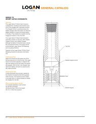
SerieS 20 Short catch SUcKer roD overShotS<br />
CALCuLAtED StREngthS<br />
Maximum Catch Size (Basket) 7/8 1 1-1/4 1-3/8 1-1/2 1-3/4 1-13/16<br />
nominal overshot o.D. * 1-9/32 1-13/32 1-5/8 1-3/4 1-29/32 2-1/4 2-5/16<br />
Load Capacity @ yield point (lbs) 31,500 31,500 42,200 35,100 41,000 50,298 50,400<br />
Bowl <strong>Logan</strong> part no. B 0 B 0 B 0 B 0 B 0 5 B 0 55 B 0 6<br />
Bowen No. 17317 25782 28762 18357 11556 47465 17439<br />
Complete Assembly <strong>Logan</strong> part no. 0- 5-D 0- 8-D 0- 6 -D 0- 75-D 0- 9 -D 0- 5-D 0- -D<br />
Bowen No. 17315 25780 28760 18355 11555 47464 17438<br />
Maximum Catch Size (Basket) 2-1/8 2-1/8 2-3/8 2-1/2<br />
nominal overshot o.D. * 2-25/32 2-7/8 3-1/8 3-1/4<br />
Load Capacity @ yield point (lbs) 102,300 101,800 127,000 127,000<br />
Bowl <strong>Logan</strong> part no. B 0 7 B 0 8 B 0 9 B 0 0<br />
Bowen No. 18307 20171 20647 22272<br />
Complete Assembly <strong>Logan</strong> part no. 0- 78-D 0- 87-A 0- -D 0- 5-A<br />
Bowen No. 18305 20170 20645 22270<br />
Strengths are theoretical yield points that are accurate within 20%.<br />
Strengths assume full grapple engagement of a round fish and a straight, steady pull.<br />
Anything less than full engagement or steady, straight pulling will reduce the listed strength.<br />
* Check the actual tool OD if the tool is to be run through a tight clearance.
SerieS 20 Short catch SUcKer roD overShotS<br />
A<br />
W<br />
F N Rod O.D.<br />
P<br />
C<br />
Diameter of Bead<br />
Does Not Exceed “F”<br />
L<br />
DIMEnSIonS AnD CALCuLAtED StREngthS<br />
Rod Size — Inches 1/2 5/8 3/4 7/8 1 1-1/8<br />
A — pin Length 1 1-1/8 1-3/8 1-3/8 1-3/4 2<br />
C — Full Sized Coupling o.D. 1 1-1/2 1-5/8 1-13/16 2-3/16 or 2 * 2-3/8<br />
F — Shoulder o.D. 1 1-3/8 1-1/2 1-5/8 2 2-1/4<br />
L — Minimum Length 2-3/4 4 4 4 4 4-1/2<br />
n — Wrench Flat 5/8 7/8 1 1 1-5/16 1-1/2<br />
p — pin o.D. 3/4 15/16 1-1/16 1-3/16 1-3/8 1-9/16<br />
W — Coupling Wrench Flat Width 3/4 1-3/8 1-1/2 1-5/8 1-7/8 2-1/8<br />
thread 3/4 10 thd 15/16 10 thd 1-1/16 10 thd 1-3/16 10 thd 1-3/8 10 thd 1-9/16 10 thd<br />
* Used when running 1-inch rods in 2-7/8" tubing; 2-3/16" is standard.<br />
7
8<br />
SerieS 20 Short catch SUcKer roD overShotS<br />
StREngth tABLE<br />
Rod Size — Inches 1/2 5/8 3/4 7/8 1<br />
Rod Area 0.196 0.306 0.442 0.601 0.785<br />
Based on:<br />
J&L Type 7 with ultimate tensile strength Yield 16,000 21,400 30,900 42,100 55,000<br />
of 86,000 and yield of 70,000 psi Ultimate 20,000 26,300 38,000 51,700 67,500<br />
Torque * 70 140 171 381 570<br />
J&L Type 2 with ultimate tensile strength Yield … 19,900 28,700 39,100 51,000<br />
of 100,000 and yield of 65,000 psi Ultimate … 30,600 44,200 60,100 78,500<br />
Torque * 65 130 159 353 530<br />
J&L Type 1 with ultimate tensile strength Yield … 20,900 30,300 41,200 53,800<br />
of 100,000 and yield of 65,000 psi Ultimate … 30,600 44,200 60,100 78,500<br />
Torque * 68-1/2 136 168 372 560<br />
J&L Type 12 with ultimate tensile strength Yield … 29,400 42,300 57,700 75,300<br />
of 120,000 and yield of 96,000 psi Ultimate … 37,700 53,000 72,000 94,200<br />
Torque * 96 192 235 476 783<br />
* Torque based on rod O.D. @ yield.
<strong>Logan</strong> SerieS 70 Short catch overShotS<br />
CALCuLAtED StREngthS<br />
Maximum Catch Size (Basket) 1-5/8 2-1/2 2-5/8 3-1/16 3-1/16 3-1/16 3-3/8<br />
overshot o.D. 2-5/16 3-5/8 3-3/4 3-15/16 4-5/8 4-1/8 4-3/8<br />
Complete Assembly <strong>Logan</strong> part no. 70- -D 70- 6 -D 70- 75-D 70- 9 -D 70- 6 -A 70- -D 70- 8-D<br />
Bowen No. 38506 17615 13535 63892 11290 10434 C-11023<br />
Bowl <strong>Logan</strong> part no. C 000 C 00 C 00 C 00 5 C 00 C 00 C 00 5<br />
Bowen No. 38508 17617 13537 63894 11291 10436 B-11025<br />
Basket grapple Load Capacity @ yield point (lbs):<br />
Max. Capacity with Stop … … 239,800 … 398,100 212,700 …<br />
Min. Capacity Without Stop 85,200 263,600 239,800 224,600 398,100 212,700 250,300<br />
Max. Make-up torque 50% of yield (ft/lbs) 600 2,550 2,800 … … 4,000 4,600<br />
Maximum Catch Size (Basket) 3-21/32 3-21/32 3-3/4 3-3/4 4-1/4 4-3/4 5-1/4<br />
overshot o.D. 4-11/16 5-5/8 4-3/4 5-1/2 5-3/4 5-7/8 6-1/4<br />
Complete Assembly <strong>Logan</strong> part no. 70- 68-D 70-56 -A 70- 75-D 70-550-A 70-575-A 70-587-D 70-6 5-D<br />
Bowen No. 10543 11297 12645 12785 13065 10560 14805<br />
Bowl <strong>Logan</strong> part no. C 005 C 006 C 007 C 008 C 009 C 0 0 C 0 05<br />
Bowen No. 10545 11299 12646 12787 13067 10562 14807<br />
Basket grapple Load Capacity @ yield point (lbs):<br />
Max. Capacity with Stop 197,600 635,700 267,100 504,500 467,400 306,200 …<br />
Min. Capacity Without Stop 197,600 790,500 267,100 558,100 575,600 348,200 319,700<br />
Max. Make-up torque 50% of yield (ft/lbs) 5,000 … … … 7,400 … 8,100<br />
Notes:<br />
1) All strengths are calculated theoretical yield points and are accurate within 20%. All strengths assume a straight, steady pull and<br />
full grapple engagement of a round fish. Anything less than straight pulling or full engagement will substantially reduce the strength.<br />
2) No tong marks should be applied to the bowl. Tong marks and other surface damage to the bowl will also reduce the strength.<br />
3) Maximum recommended makeup torque is 50% of yield. Less torque may be used depending upon the situation.<br />
4) Jarring may amplify the pull load by a factor of 3 to 10.<br />
9
0<br />
<strong>Logan</strong> SerieS 70 Short catch overShotS<br />
CALCuLAtED StREngthS<br />
Maximum Catch Size (Basket) 4-3/4 6 6-1/4 6-1/2 7 7-3/4 8<br />
overshot o.D. 6-5/8 7-5/8 7-7/8 8-1/4 8-1/2 9-1/4 9-3/4<br />
Complete Assembly <strong>Logan</strong> part no. 70-66 -A 70-76 -A 70-787-A 70-8 5-A 70-850-A 70-9 5-A 70-975-A<br />
Bowen No. 11303 11630 16975 38939 20050 25030 20060<br />
Bowl <strong>Logan</strong> part no. C 0 C 0 C 0 C 0 C 0 5 C 0 6 C 0 7<br />
Bowen No. 11305 11632 16977 38941 20052 25032 20062<br />
Basket grapple Load Capacity @ yield point (lbs):<br />
Max. Capacity with Stop 579,400 358,000 349,200 … 285,100 … …<br />
Min. Capacity Without Stop 720,600 445,300 445,700 445,100 373,700 391,700 445,100<br />
Max. Make-up torque 50% of yield (ft/lbs) … 12,500 … 22,000 24,200 27,800 30,800<br />
Maximum Catch Size (Basket) 9 13-3/8<br />
overshot o.D. 11-1/4 16<br />
Complete Assembly <strong>Logan</strong> part no. 70- 5-A 70- 600-A<br />
Bowen No. 33878 …<br />
Bowl <strong>Logan</strong> part no. C 0 8 C 0 9<br />
Bowen No. 33880 …<br />
Basket grapple Load Capacity @ yield point (lbs):<br />
Max. Capacity with Stop … …<br />
Min. Capacity Without Stop 874,800 …<br />
Max. Make-up torque 50% of yield (ft/lbs) 42,000 55,500<br />
Notes:<br />
1) All strengths are calculated theoretical yield points and are accurate within 20%. All strengths assume a straight, steady pull and<br />
full grapple engagement of a round fish. Anything less than straight pulling or full engagement will substantially reduce the strength.<br />
2) No tong marks should be applied to the bowl. Tong marks and other surface damage to the bowl will also reduce the strength.<br />
3) Maximum recommended makeup torque is 50% of yield. Less torque may be used depending upon the situation.<br />
4) Jarring may amplify the pull load by a factor of 3 to 10.
<strong>Logan</strong> SerieS 150 reLeaSing & circULating overShotS<br />
CALCuLAtED StREngthS<br />
Maximum Load Capacity @ yield point (lbs)<br />
Complete <strong>Logan</strong> Bowen Catch Size w/ overshot Spiral Basket grapple<br />
Assembly Bowl no. Bowl no. Spiral grapple o.D. (in) grapple w/o Stop w/ Stop<br />
150-231-D A1950 B-8921 2 2-5/16 50,400 36,300 28,900<br />
150-263-D A2000 B-10201 2-1/8 2-5/8 101,600 86,400 61,000<br />
150-313-E A2001 9306 2-3/8 3-1/8 193,500 173,200 118,000<br />
150-350-A A2002 B-4743 2-3/8 3-1/2 309,000 265,500 167,000<br />
150-412-B A20025 1446 2-3/8 4-1/8 455,000 390,000 265,000<br />
150-338-D A2003 B-5088 2-1/2 3-3/8 258,000 213,300 163,500<br />
150-363-A A2004 B-5082 2-1/2 3-5/8 346,200 307,700 219,800<br />
150-363-E A2005 9271 2-7/8 3-5/8 193,500 157,400 78,700<br />
150-375-D A20055 37587 3-1/16 3-3/4 217,700 221,200 179,700<br />
150-388-D A20056 B-1836 3-1/8 3-7/8 155,100 144,200 98,000<br />
150-376-D A20057 B-1828 2-7/8 3-3/4 214,000 192,800 121,400<br />
150-400-A A2006 B-4738 2-7/8 4 304,000 221,500 199,000<br />
150-393-D A2007 B-5103 3-1/16 3-15/16 265,400 219,000 160,100<br />
150-419-A A2008 B-5100 3-1/16 4-3/16 291,800 263,000 118,200<br />
150-400-D A2009 B-5106 3-1/8 4 262,900 217,000 125,100<br />
150-413-A A2010 9107 3-1/8 4-1/8 310,200 255,000 170,000<br />
150-412-A A20105 8223 3-1/8 4-1/8 310,200 255,000 170,000<br />
150-425-A A2011 B-4824 3-1/8 4-1/4 291,800 263,000 118,200<br />
150-413-D A2012 B-5117 3-1/4 4-1/8 225,000 202,000 127,500<br />
150-438-A A2013 B-5114 3-1/4 4-3/8 254,000 234,200 147,500<br />
150-388-E A20135 21302 3-3/8 3-7/8 102,500 97,500 66,500<br />
150-425-D A2014 B-5128 3-3/8 4-1/4 262,900 217,000 116,800<br />
150-4375-A A20145 9637 3-3/8 4-3/8 281,500 249,400 167,900<br />
150-450-A A2015 B-5125 3-3/8 4-1/2 320,000 280,000 176,000<br />
150-438-D A2016 B-4621 3-1/2 4-3/8 267,400 220,700 144,300<br />
150-482-A A2017 B-4734 3-1/2 4-13/16 456,000 396,000 286,000
<strong>Logan</strong> SerieS 150 reLeaSing & circULating overShotS<br />
CALCuLAtED StREngthS<br />
Maximum Load Capacity @ yield point (lbs)<br />
Complete <strong>Logan</strong> Bowen Catch Size w/ overshot Spiral Basket grapple<br />
Assembly Bowl no. Bowl no. Spiral grapple o.D. (in) grapple w/o Stop w/ Stop<br />
150-451-D A20161 A-3795 3-1/2 4-1/2 271,000 226,000 146,500<br />
150-450-D A20175 17203 3-21/32 4-17/32 260,400 233,400 170,500<br />
150-456-D A2018 B-5153 3-21/32 4-9/16 276,400 228,100 157,900<br />
150-469-C A2019 9111 3-21/32 4-11/16 332,000 279,000 199,500<br />
150-500-A A2020 B-5150 3-21/32 5 394,000 338,000 210,000<br />
150-463-D A2021 B-5131 3-3/4 4-5/8 270,600 218,000 150,900<br />
150-468-C A20215 9121 3-3/4 4-11/16 261,300 233,000 138,000<br />
150-444-D A20217 B-9775 3-13/16 4-7/16 137,500 118,000 44,800<br />
150-513-A A2022 B-4688 3-3/4 5-1/8 489,000 447,000 354,000<br />
150-525-A A2023 9517 3-7/8 5-1/4 451,000 389,500 276,500<br />
150-462-D A20235 B-6232 3-7/8 4-5/8 186,800 166,700 104,200<br />
150-488-D A2024 B-5156 4 4-7/8 385,000 241,000 167,000<br />
150-531-A A2025 B-5144 4 5-5/16 402,000 351,000 273,000<br />
150-500-D A2026 B-5430 4-1/8 5 296,000 258,500 201,000<br />
150-544-A A2027 B-5427 4-1/8 5-7/16 547,600 435,500 277,100<br />
150-512-D A20285 4717 4-1/4 5-1/8 312,500 264,000 196,000<br />
150-513-D A2028 B-5164 4-1/4 5-1/8 356,800 301,000 232,200<br />
150-556-A A2029 5898 4-1/4 5-9/16 526,600 494,300 362,500<br />
150-555-A A20295 B-4821 4-1/4 5-9/16 439,200 396,000 286,000<br />
150-538-D A2030 B-5167 4-1/2 5-3/8 279,000 258,000 186,200<br />
150-581-A A2031 B-4816 4-1/2 5-13/16 439,200 396,000 286,000<br />
150-550-D A20315 B-4971 4-5/8 5-1/2 297,000 258,000 186,200<br />
150-563-A A2032 5700 4-5/8 5-5/8 420,000 378,500 273,000<br />
150-594-A A2033 5735 4-5/8 5-15/16 514,100 421,300 297,400<br />
150-563-D A2034 B-5170 4-3/4 5-5/8 360,400 308,400 234,500<br />
150-575-A A2035 8977 4-3/4 5-3/4 432,900 411,600 303,275
<strong>Logan</strong> SerieS 150 reLeaSing & circULating overShotS<br />
CALCuLAtED StREngthS<br />
Maximum Load Capacity @ yield point (lbs)<br />
Complete <strong>Logan</strong> Bowen Catch Size w/ overshot Spiral Basket grapple<br />
Assembly Bowl no. Bowl no. Spiral grapple o.D. (in) grapple w/o Stop w/ Stop<br />
150-606-A A2036 B-4831 4-3/4 6-1/16 431,000 381,000 275,500<br />
150-575-D A2037 B-7098 4-7/8 5-3/4 273,500 230,700 178,000<br />
150-613-A A20375 905 4-7/8 6-1/8 405,000 367,000 298,000<br />
150-619-A A2038 B-7095 4-7/8 6-3/16 404,500 341,200 282,700<br />
1150-588-D A2039 B-5173 5 5-29/32 323,500 283,500 218,500<br />
150-612-C A20395 7788 5 6-1/8 468,000 440,000 322,000<br />
150-663-A A2040 B-4827 5 6-5/8 637,000 574,300 462,000<br />
150-576-D A20402 B-11825 5-1/8 5-3/4 135,000 115,000 71,500<br />
150-638-D A20405 4503 5-1/4 6-3/8 403,000 356,000 256,000<br />
150-650-D A20407 9205 5-3/8 6-1/2 385,500 325,000 232,000<br />
150-663-D A2041 8617 5-1/2 6-5/8 386,000 325,000 232,000<br />
150-713-A A2042 B-2791 5-1/2 7-1/8 637,500 574,300 462,000<br />
150-688-D A2043 8980 5-3/4 6-7/8 367,000 332,000 253,000<br />
150-738-A A2044 B-3522 5-3/4 7-3/8 637,500 574,300 462,000<br />
150-763-A A2045 7574 6 7-5/8 611,300 532,600 404,300<br />
150-725-D A2046 B-5208 6-1/8 7-1/4 435,000 392,000 298,000<br />
150-775-A A2047 B-4218 6-1/8 7-3/4 637,000 574,300 462,000<br />
150-738-D A2048 9694 6-1/4 7-3/8 450,400 427,283 327,900<br />
150-762-C A20485 1875 6-1/4 7-5/8 542,468 479,044 364,490<br />
150-763-C A2049 1641 6-1/4 7-5/8 502,100 449,900 363,200<br />
150-777-A A20495 1657 6-1/4 7-7/8 627,600 542,400 395,000<br />
150-788-A A2050 B-2109 6-1/4 7-7/8 586,800 515,600 413,700<br />
150-750-D A2051 9011 6-3/8 7-1/2 479,000 454,000 339,000<br />
150-775-C A2052 9164 6-3/8 7-3/4 385,500 325,000 232,000<br />
150-763-D A2053 9862 6-1/2 7-5/8 418,200 396,700 322,900<br />
150-813-A A2054 B-3711 6-1/2 8-1/8 586,500 515,500 413,500
<strong>Logan</strong> SerieS 150 reLeaSing & circULating overShotS<br />
CALCuLAtED StREngthS<br />
Maximum Load Capacity @ yield point (lbs)<br />
Complete <strong>Logan</strong> Bowen Catch Size w/ overshot Spiral Basket grapple<br />
Assembly Bowl no. Bowl no. Spiral grapple o.D. (in) grapple w/o Stop w/ Stop<br />
150-775-D A2055 9134 6-5/8 7-3/4 422,000 400,000 318,000<br />
150-825-A A2056 B-3034 6-5/8 8-1/4 637,500 574,300 462,000<br />
150-788-D A2057 B-5224 6-3/4 7-7/8 531,900 467,300 375,000<br />
150-838-A A2058 277 6-3/4 8-3/8 637,000 542,250 408,250<br />
150-800-D A20587 M-8997 6-7/8 8 436,000 406,900 350,000<br />
150-814-D A20590 9817 7 8-1/8 453,000 429,500 329,500<br />
150-813-D A2059 9219 7 8-1/8 453,000 429,500 329,500<br />
150-812-D A20595 B-3264 7 8-1/8 439,200 395,800 318,400<br />
150-837-D A20598 17209 7 8-3/8 587,977 557,764 428,051<br />
150-863-A A2060 B-3819 7 8-5/8 637,000 574,300 462,000<br />
150-825-D A20605 9571 7-1/8 8-1/4 422,000 400,000 307,300<br />
150-838-D A2061 B-5356 7-1/4 8-3/8 430,000 385,000 295,000<br />
150-888-A A2062 M-1026-1 7-1/4 8-7/8 586,900 515,600 426,500<br />
150-850-D A2063 9233 7-3/8 8-1/2 422,000 400,000 309,000<br />
150-900-A A2064 B-5232 7-3/8 9 637,000 574,300 462,000<br />
150-863-D A2065 B-7103 7-1/2 8-5/8 436,000 385,000 309,000<br />
150-913-A A2066 B-4516 7-1/2 9-1/8 637,000 574,300 462,000<br />
150-875-D A2067 9239 7-5/8 8-3/4 458,000 435,000 333,000<br />
150-762-A A20675 B-5243 7-5/8 9-1/4 657,000 578,000 465,000<br />
150-888-D A2068 9852 7-3/4 8-7/8 458,000 435,000 333,000<br />
150-889-D A2069 B-5259 7-3/4 8-7/8 430,000 385,000 295,000<br />
150-937-A A20695 1283 7-3/4 9-3/8 637,000 542,250 408,250<br />
150-938-A A2070 B-1501 7-3/4 9-3/8 592,000 520,000 340,000<br />
150-913-D A2071 B-5267 8 9-1/8 396,000 347,500 236,000<br />
150-963-A A2072 266 8 9-5/8 602,700 510,750 398,600<br />
150-950-D A2073 9062 8-3/8 9-1/2 447,500 424,500 325,500
<strong>Logan</strong> SerieS 150 reLeaSing & circULating overShotS<br />
CALCuLAtED StREngthS<br />
Maximum Load Capacity @ yield point (lbs)<br />
Complete <strong>Logan</strong> Bowen Catch Size w/ overshot Spiral Basket grapple<br />
Assembly Bowl no. Bowl no. Spiral grapple o.D. (in) grapple w/o Stop w/ Stop<br />
150-1006-A A2074 B-1231 8-3/8 10-1/16 637,500 574,300 462,000<br />
150-963-D A2075 B-5286 8-1/2 9-5/8 419,500 376,000 341,000<br />
150-1013-A A2076 8962 8-1/2 10-1/8 602,700 492,000 391,000<br />
150-1025-D A2077 B-5299 8-5/8 10-1/4 657,000 578,000 465,000<br />
150-1050-A A2078 B-5307 8-7/8 10-1/2 586,600 515,400 413,600<br />
150-1063-A A2079 B-5323 9 10-5/8 586,800 515,600 426,500<br />
150-1125-A A2080 B-12824 9-5/8 11-1/4 586,800 515,600 413,700<br />
150-1138-A A2081 26257 9-3/4 11-3/8 565,900 502,900 380,000<br />
150-1175-A A2082 5331 10-1/8 11-3/4 616,000 528,000 435,000<br />
150-1275-A A2083 15802 11-1/4 12-3/4 605,000 562,250 444,000<br />
150-1375 A2084 33008 12 13-3/4 1,022,314 745,564 …<br />
150-1600 A2085 68030 14 16 1,164,000 1,175,000 …<br />
150-1675 A2086 64555 14-3/4 16-3/4 1,197,674 1,226,777 …<br />
150-2075 A2087 31655 16-3/4 20-1/4 … 1,479,060 1,344,600<br />
Notes:<br />
1) All strengths are calculated theoretical yield points and are accurate within 20%. All strengths assume a straight, steady pull and<br />
full grapple engagement of a round fish. Anything less than straight pulling or full engagement will substantially reduce the strength.<br />
2) No tong marks should be applied to the bowl. Tong marks and other surface damage to the bowl will also reduce the strength.<br />
5
6<br />
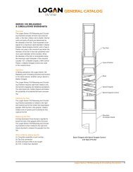
<strong>Logan</strong> SUperior hyDraULic fiShing jarS<br />
Mandrel Extension to Washpipe<br />
Mandrel to Mandrel Extension<br />
(internal connection)<br />
(internal connection)<br />
Connector<br />
Mandrel Spline Body<br />
Balance Body Body Pressure Body<br />
Washpipe Body<br />
Floater Body<br />
StREngth AnD tESt DAtA<br />
Complete Assembly 6 - 06 6 - 6 - 6 - 75 6 - 76 6 - 5 6 - 50 6 - 75 6 -6 5 6 -775<br />
outside Diameter (in) 3-1/16 3-1/8 3-1/8 3-3/4 3-3/4 4-1/4 4-1/2 4-3/4 6-1/4 7-3/4<br />
Jar tester Low test pull Load — Min (lbs) 7,000 9,000 7,000 12,000 12,000 12,000 12,000 15,000 18,000 18,000<br />
JAR tEStER LoW tESt puD — Max (lbs)<br />
12,000 12,000 12,000 16,000 16,000 16,000 16,000 20,000 26,000 26,000<br />
Jar tester Standard pull test (lbs) 18,000 30,000 18,000 35,000 35,000 35,000 30,000 50,000 100,000 100,000<br />
Field Load — Max pull Load 36,000 55,000 36,000 72,000 51,000 75,000 60,000 100,000 200,000 275,000<br />
Lift Load After Jarring, Jar Fully Extended<br />
185,000 253,000 185,000 330,000 285,000 375,000 360,000 505,000 1,000,000 1,600,000<br />
tensile @ yield (lbs)<br />
torque @ yield (ft-lbs) 4,200 7,500 4,200 14,500 9,650 18,500 12,000 18,100 40,800 79,000<br />
MAXIMuM RECoMMEnDED tIghtEnIng toRQuES (Ft-LBS)<br />
Spline Body to Balance Body 2,100 2,700 2,100 3,500 3,650 5,000 3,500 9,090 20,000 39,000<br />
Balance Body to Connector Body 2,100 2,700 2,100 3,500 3,650 5,000 3,500 9,090 20,000 39,000<br />
Connector Body to pressure Body 2,100 2,700 2,100 3,500 3,650 5,000 3,500 9,090 20,000 39,000<br />
Mandrel to Mandrel Extension 700 800 700 800 800 1,700 900 1,800 7,000 12,500<br />
pressure Body to Floater Body 2,100 2,700 2,100 3,500 3,650 5,000 3,500 9,090 20,000 39,000<br />
Mandrel Extension to Washpipe 600 700 600 700 700 1,500 800 1,000 4,800 10,500<br />
Floater Body to Washpipe Body 2,100 2,700 2,100 3,500 3,650 5,000 3,500 9,090 20,000 39,000
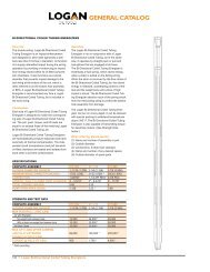
<strong>Logan</strong> SUperior energizerS<br />
Mandrel to Mandrel Extension<br />
Mandrel Extension to Washpipe<br />
(internal connection)<br />
(internal connection)<br />
Connector<br />
Mandrel Spline Body<br />
Balance Body Body<br />
Pressure Body Washpipe Body<br />
StREngth AnD tESt DAtA<br />
Complete Assembly 6 - 06 6 - 6 - 6 - 75 6 - 76 6 - 5 6 - 50 6 - 75 6 -6 5 6 -775<br />
outside Diameter (in) 3-1/16 3-1/8 3-1/8 3-3/4 3-3/4 4-1/4 4-1/2 4-3/4 6-1/4 7-3/4<br />
Jar tester Low test pull Load — Min (lbs) 7,000 9,000 7,000 12,000 12,000 12,000 12,000 15,000 18,000 18,000<br />
Jar tester Low test pull Load — Max (lbs) 12,000 12,000 12,000 16,000 16,000 16,000 16,000 20,000 26,000 26,000<br />
Jar tester Standard pull test (lbs) 18,000 30,000 18,000 35,000 35,000 35,000 30,000 50,000 100,000 100,000<br />
Field Load — Max pull Load 36,000 55,000 36,000 72,000 51,000 75,000 60,000 100,000 200,000 275,000<br />
Lift Load After Jarring, Jar Fully Extended,<br />
185,000 253,000 185,000 330,000 285,000 375,000 360,000 505,000 1,000,000 1,600,000<br />
tensile @ yield (lbs)<br />
torque @ yield (ft-lbs) 4,200 7,500 4,200 14,500 9,650 18,500 12,000 18,100 40,800 79,000<br />
MAXIMuM RECoMMEnDED tIghtEnIng toRQuES (Ft-LBS)<br />
Spline Body to Balance Body 2,100 2,700 2,100 3,500 3,500 5,000 5,000 9,090 20,000 39,000<br />
Mandrel to Mandrel Extension 700 800 700 800 700 1,700 1,500 1,800 7,000 12,500<br />
Balance Body to Connector Body 2,100 2,700 2,100 3,500 3,500 5,000 5,000 9,090 20,000 39,000<br />
Connector Body to pressure Body 2,100 2,700 2,100 3,500 3,500 5,000 5,000 9,090 20,000 39,000<br />
Mandrel Extension to Washpipe 600 700 600 700 700 1,500 1,500 1,000 4,800 10,500<br />
pressure Body to Washpipe Body 2,100 2,700 2,100 3,500 3,500 5,000 5,000 9,090 20,000 39,000<br />
7
8<br />
<strong>Logan</strong> SUrface BUmper jarS<br />
Washpipe to Bottom Sub<br />
(internal connection)<br />
Bowl Bottom Sub<br />
Top Sub to Main Mandrel<br />
Main Mandrel to Friction Mandrel<br />
(internal connection)<br />
(internal connection)<br />
Knocker Sub<br />
Top Sub Bowl Extension<br />
StREngth AnD tESt DAtA<br />
Complete Assembly 609-00<br />
outside Diameter (in) 7<br />
Bowl outside Diameter (in) 9<br />
Max torque @ yield (ft-lbs) 33,800<br />
Max tensile Load @ yield (ft-lbs) 845,000<br />
Max pump pressure (psi) 8,000<br />
Setting Load (tons) 0 – 50<br />
MAXIMuM RECoMMEnDED tIghtEnIng toRQuES (Ft-LBS)<br />
top Sub to Main Mandrel 16,900<br />
knocker Sub Bowl Extension 16,900<br />
Bowl Extension to Bowl 17,900<br />
Main Mandrel to Friction Mandrel 2,700<br />
Washpipe to Bottom Sub 2,700<br />
Bowl to Bottom Sub 17,900
<strong>Logan</strong> LUBricateD fiShing BUmper SUBS<br />
Mandrel to Washpipe<br />
(internal connection)<br />
Knocker to Mandrel<br />
(internal connection)<br />
Washpipe Body<br />
Mandrel Mandrel Body<br />
Middle Body<br />
StREngth AnD tESt DAtA<br />
Complete Assembly 607-181 607-225 607-312 607-375 607-376 607-377 607-425 607-450 607-475 607-476 607-600 607-625 607-675 607-775<br />
outside Diameter (in) 1-13/16 2-1/4 3-1/8 3-3/4 3-3/4 3-3/4 4-1/4 4-1/2 4-3/4 4-3/4 6 6-1/4 6-3/4 7-3/4<br />
tensile Strength (lbs) 75,400 116,415 239,070 363,780 300,750 291,735 397,650 388,650 484,650 433,000 622,295 777,150 1,130,400 1,276,950<br />
Bumper Sub yield torque (ft-lbs) 480 1,740 3,400 7,100 7,100 4,920 9,260 7,100 11,030 15,000 23,000 32,600 43,200 62,400<br />
Max operating torque (ft-lbs) 240 870 1,700 3,550 3,550 2,460 4,630 3,550 5,518 7,500 11,500 16,300 21,600 31,200<br />
MAXIMuM RECoMMEnDED tIghtEnIng toRQuES (Ft-LBS)<br />
Mandrel to Mandrel Body 240 … … … … … … … … … … … … …<br />
Mandrel Body to Middle Body 370 870 1,700 3,550 3,550 2,460 4,630 3,550 7,500 7,500 11,500 16,300 21,600 31,200<br />
knocker to Mandrel … 90 430 580 410 330 670 370 1,100 1,000 2,270 3,120 3,000 7,690<br />
Mandrel to Washpipe … 140 660 500 490 1,220 730 1,450 1,690 1,500 3,800 9,750 13,300 21,000<br />
Middle Body to Washpipe Body 370 870 1,700 3,550 3,550 2,460 4,630 3,550 7,500 7,500 13,500 16,300 22,600 31,200<br />
9
0<br />
0.625<br />
45° 1/2 Max.<br />
0.62R<br />
D L<br />
D LF<br />
C<br />
api nUmBereD<br />
rotary ShoULDereD connectionS<br />
L PC<br />
See Note<br />
0.625<br />
D S Q C<br />
See Note<br />
Note: Extent of bevel on pin and box starting thread is optional with manufacturer.<br />
Thread Thread Lg. Dia. Flat Sm. Dia Box Pin Box<br />
Form, Taper, Pitch Dia. of Pin, on Pin of Pin Depth Length Counterbore<br />
Conn. Inch Thds. In/Ft @ Gauge Pt. Reference DLF DS LBC LPC QC<br />
No. * Radius Per In on Dia. C DL ± 1/64 +0 –3/8 +0 –3/8 +0 –1/8 +1/32 –0<br />
23 0.038 4 2 2.355 2.563 2.437 2.063 3-5/8 3 2-5/8<br />
26 ** 0.038 4 2 2.668 2.876 2.750 2.376 3-5/8 3 2-15/16<br />
31 ** 0.038 4 2 3.183 3.391 3.266 2.808 4-1/8 3-1/2 3-29/64<br />
35 0.038 4 2 3.531 3.739 3.625 3.114 4-3/8 3-3/4 3-13/16<br />
38 ** 0.038 4 2 3.808 4.016 3.891 3.349 4-5/8 4 4-5/64<br />
40 ** 0.038 4 2 4.072 4.280 4.156 3.630 5-1/8 4-1/2 4-11/32<br />
44 0.038 4 2 4.417 4.625 4.499 8.875 5-1/8 4-1/2 4-11/16<br />
46 ** 0.038 4 2 4.626 4.834 4.709 4.084 5-1/8 4-1/2 4-29/32<br />
50 ** 0.038 4 2 5.0417 5.250 5.125 4.500 5-1/8 4-1/2 5-5/16<br />
56 0.038 4 3 5.616 5.876 5.703 4.626 5-5/8 5 5-15/16<br />
61 0.038 4 3 6.178 6.438 6.266 6.063 6-1/8 5-1/2 6-1/2<br />
70 0.038 4 3 7.053 7.313 7.141 6.813 6-5/8 6 7-3/8<br />
77 0.038 4 3 7.741 8.000 7.828 6.376 7-1/8 6-1/2 8-1/16<br />
All dimensions are in inches.<br />
* The connection number is the diameter of the connection at the gauge point rounded to units<br />
and tenths of inches.<br />
** See Table 12 below for interchangeability of numbered rotary shouldered connections with rotary<br />
shouldered connections of Table 9.1.<br />
taBLe 12<br />
IntERChAngEABILIty oF nuMBERED RotARy ShouLDERED ConnECtIonS<br />
WIth tABLE 9. RotARy ShouLDERED ConnECtIonS<br />
45°<br />
numbered Connection Equivalent Connection of table 9.<br />
26 2-3/8 IF<br />
31 2-7/8 IF<br />
38 3-1/2 IF<br />
40 4 FH<br />
46 4 IF<br />
50 4-1/2 IF<br />
L BC
api regULar — Union tooL regULar<br />
G<br />
A<br />
5 Thd. 3 TPF .118<br />
5 Thd. 2 TPF .119<br />
4 Thd. 3 TPF .147<br />
4 Thd. 2 TPF .148<br />
ApI REguLAR — unIon tooL REguLAR<br />
Size A B C D E F g h k<br />
2-3/8 3 3-1/8 2-5/8 1-7/8 2-11/16 3-3/8 1 5 3<br />
2-7/8 3-1/2 3-3/4 3 2-1/8 3-1/16 3-7/8 1-1/4 5 3<br />
3-1/2 3-3/4 4-1/4 3-1/2 2-9/16 3-9/16 4-1/8 1-1/2 5 3<br />
4-1/2 4-1/4 5-1/2 * 4-5/8 3-9/16 4-11/16 4-5/8 2-1/4 5 3<br />
5-1/2 4-3/4 6-3/4 5-33/64 4-21/64 5-37/64 5-1/8 2-3/4 4 3<br />
6-5/8 ** 5 7-3/4 6 5-5/32 6-1/16 5-3/8 3-1/2 4 2<br />
7-5/8 5-1/4 8-7/8 7 5-11/16 7-1/16 5-5/8 4 4 3<br />
8-5/8 5-3/8 10 7-61/64 6-39/64 8-1/64 5-3/4 4-3/4 4 3<br />
* 5-3/4 O.D. is optional.<br />
** Threaded portion same as 5-1/2 Union Tool Full Hole.<br />
H - Threads per Inch<br />
F<br />
K - Incl. Taper 5/8 C’Bore<br />
D<br />
.015R<br />
C<br />
B<br />
E<br />
.020R - 5 Thd.<br />
.025R - 4 Thd.<br />
.040 Flat - 5 Thd.<br />
30° 30° .050 Flat - 4 Thd.<br />
90°<br />
.200 5 Thd.<br />
.250 4 Thd.<br />
.015R<br />
G<br />
30°
api fULL hoLe — Union tooL fULL hoLe<br />
G<br />
4 Thd. 3 TPF<br />
A<br />
.147<br />
4 Thd. 2 TPF<br />
.148<br />
5 Thd. 3 TPF<br />
.118<br />
Size A B C D E F g h k<br />
2-7/8 * 3-1/2 4-1/4 3-5/8 2-3/4 3-11/16 3-9/16 2-1/8 5 3<br />
3-1/2 3-3/4 4-5/8 4 3-1/16 4-3/64 4-3/8 2-1/8 ** 5 3<br />
4 4-1/2 5-1/4 4-9/32 3-17/32 4-11/32 5-1/8 2-13/16 4 † 2<br />
4-1/2 4 5-3/4 4-51/64 3-51/64 4-7/8 4-5/8 3 5 3<br />
5-1/2 5 7 5-53/64 5 5-29/32 5-5/8 4 4 2<br />
6-5/8 5 8 6-3/4 5-59/64 6-27/32 5-5/8 5 4 2<br />
* Not API Standard.<br />
** I.D. changed from 2-7/16", May 1979 (API)<br />
† Thread form same as API-IF joint.<br />
H - Threads per Inch<br />
K - Incl. Taper 5/8<br />
D<br />
.015R<br />
C<br />
ApI FuLL hoLE — unIon tooL FuLL hoLE<br />
B<br />
E<br />
.020R - 5 Thd.<br />
.025R - 4 Thd.<br />
30° 30°<br />
90°<br />
.200<br />
.250<br />
5 Thd.<br />
4 Thd.<br />
.015R<br />
Perf. Thd.<br />
F<br />
.040 Flat - 5 Thd.<br />
.050 Flat - 4 Thd.<br />
G<br />
30°
api internaL fLUSh — hUgheS anD reeD Lf<br />
A<br />
G<br />
.015R<br />
30°<br />
H - Threads per Inch<br />
K - Incl. Taper<br />
ApI IntERnAL FLuSh — hughES AnD REED LF<br />
Size A B C D E F g h k<br />
2-3/8 3 3-3/8 2-7/8 2-3/8 2-15/16 3-3/8 1-3/4 4 2<br />
2-7/8 3-1/2 4-1/8 3-25/64 2-13/16 3-29/64 3-7/8 2-1/8 4 2<br />
3-1/2 4 4-3/4 4-1/64 3-11/32 4-5/64 4-3/8 2-11/16 4 2<br />
4 4-1/2 5-3/4 4-53/64 4-5/64 4-29/32 4-7/8 3-1/4 4 2<br />
4-1/2 4-1/2 6-1/8 5-1/4 4-1/2 5-5/16 4-7/8 3-3/4 4 2<br />
5-1/2 5 7-3/8 6-25/64 5-9/16 6-29/64 5-3/8 4-13/16 4 2<br />
Threaded portion same as 2-7/8" Hughes Slim Hole.<br />
Threaded portion same as 3-1/2" Hughes Slim Hole.<br />
Threaded portion same as 4-1/2" Hughes Slim Hole.<br />
D<br />
.250<br />
90°<br />
30°<br />
Threaded portion same as 4-1/2" Hughes Xtra Hole, 5" Reed Double Streamline,<br />
and 4-1/2" Reed Xtra Hole.<br />
Threaded portion same as 5-1/2" Reed Double Streamline, 5" Hughes Xtra Hole,<br />
and 5" Reed Xtra Hole.<br />
C<br />
B<br />
E<br />
.056<br />
5/8<br />
.015R<br />
.065<br />
.1114<br />
Axis<br />
Perf. Thd.<br />
F<br />
30°<br />
G
.31<br />
american mt, amt, anD ammt *<br />
.015 R Typ<br />
Perf. Thd.<br />
A<br />
L<br />
.047<br />
45°<br />
Diameter of flat<br />
Max. cone diameter at shoulder<br />
.166<br />
30°<br />
.44<br />
G M D J C B E O<br />
90°<br />
Axis of Joint<br />
.055<br />
AMERICAn Mt, AMt, AnD AMMt<br />
Perf. Thd.<br />
N<br />
F<br />
45°<br />
.056<br />
G<br />
45°<br />
H - Threads per Inch<br />
K - Incl. Taper<br />
Size A B C D E F G H J K L M N O<br />
(in) (in) (in) (in) (in) (in) (in) (TPI) (in) (TPF) (in) (in) (in) (in)<br />
1 1-1/2 1-9/16 1.281 1.093 1.301 1-1/2 3/4 6 1.233 1-1/2 1-1/8 61/64 2 1.183<br />
1-1/4 2 1-3/4 1.469 1.218 1.489 2 3/4 6 1.421 1-1/2 1-5/8 1-3/32 2-1/2 1.371<br />
1-1/2 2 2 1.668 1.418 1.688 2 1 6 1.621 1-1/2 1-5/8 1-9/32 2-1/2 1.570<br />
* MT is Macaroni Tubing; AMT is American Macaroni Tubing;<br />
AMMT is American Mining Macaroni Tubing
A<br />
pac<br />
.38<br />
G D J C B E<br />
Diameter of straight<br />
Max. cone diameter at shoulder<br />
.015 R Typ<br />
.067<br />
pAC<br />
.250<br />
30°<br />
90°<br />
Axis of Joint<br />
Perf. Thd.<br />
F<br />
G<br />
H - Threads per Inch<br />
K - Incl. Taper<br />
Size A B C D E F g h J k<br />
(in) (in) (in) (in) (in) (in) (in) (tpI) (in) (tpF)<br />
2-3/8 2-3/8 2-7/8 2-23/64 2-1/16 2-27/64 2-1/2 1-3/8 4 2-5/16 1-1/2<br />
2-7/8 2-3/8 3-1/8 2-17/32 2-15/64 2-19/32 2-1/2 1-1/2 4 2-31/64 1-1/2<br />
3-1/2 3-1/4 3-3/4 3-3/64 2-41/64 3-7/64 3-3/8 2 4 3 1-1/2<br />
.076<br />
.093<br />
30°<br />
5
6<br />
hUgheS Xtra hoLe & reeD eXtra hoLe<br />
A<br />
H - Threads per Inch<br />
K - Incl. Taper<br />
G D C<br />
hughES XtRA hoLE & REED EXtRA hoLE<br />
Size A B C D E F g h J k<br />
2-7/8 3-7/8 4-1/4 3-21/64 2-11/16 3-23/64 4-1/2 1-7/8 4 3-15/64 2<br />
3-1/2 3-3/8 4-3/4 3-13/16 3-1/4 3-7/8 3-15/16 2-7/16 4 … 2<br />
4-1/2 4-3/8 6 4-53/64 4-7/64 4-29/32 4-15/16 3-1/4 4 … 2<br />
5 4-1/2 6-1/4 5-1/4 4-1/2 5-5/16 4-7/8 3-3/4 4 … 2<br />
Threaded portion same as 2-7/8" Reed Xtra Hole, 3-1/2" Reed Double Streamline,<br />
and 3-1/2" Hughes Double Streamline.<br />
J<br />
30° 30°<br />
.065<br />
.250<br />
Threaded portion same as 4-1/2" Hughes External Flush, 4-1/2" FH Reed External Flush,<br />
4" Hughes Slim Hole, and 3-1/2" Reed Xtra Hole.<br />
90°<br />
Threaded portion same as 4" API-IF, 5" Reed Double Sreamline, and 4-1/2" Reed Xtra Hole.<br />
Threaded portion same as 4-1/2" API-IF, 5-1/2" Reed Double Sreamline, and 5" Reed Xtra Hole.<br />
B<br />
.056<br />
E<br />
1/64 R<br />
1/64 R<br />
.1114<br />
Perf. Thd.<br />
F<br />
5/8<br />
35°<br />
Max. cone diameter at shoulder<br />
Diameter of straight section<br />
30°<br />
G
hughES SLIM hoLE<br />
Size A B C D E F g h k<br />
2-3/8 2-7/8 2-7/8 2-7/16 1-31/32 2-1/2 3-1/4 1-1/4 4 2<br />
2-7/8 2-7/8 3-3/8 2-7/8 2-25/64 2-15/16 3-1/4 1-3/4 4 2<br />
3-1/2 3-3/8 4 3-25/64 2-53/64 3-29/64 3-3/4 2-1/8 4 2<br />
4 3-3/8 4-1/2 3-13/16 3-1/4 3-7/8 3-3/4 2-9/16 4 2<br />
4-1/2 3-7/8 5 4-1/64 3-3/8 4-5/64 4-1/4 2-11/16 4 2<br />
Threaded portion same as 2-3/8" API-IF.<br />
Threaded portion same as 2-7/8" API-IF.<br />
Threaded portion same as 3-1/2" Hughes Xtra Hole, 3-1/2" Reed Xtra Hole,<br />
4-1/2" Hughes External Flush, and 4-1/2" Reed External Flush.<br />
Threaded portion same as 3-1/2" API-IF.<br />
A<br />
1/32 R<br />
G<br />
.015 R<br />
hUgheS SLim hoLe<br />
H - Threads per Inch<br />
K - Incl. Taper<br />
D<br />
C<br />
B<br />
30° 30°<br />
90°<br />
.250<br />
E<br />
.056<br />
F<br />
.065<br />
21/32<br />
.1114<br />
Perf. Thd.<br />
30°<br />
G<br />
7
8<br />
3/64 R<br />
N<br />
60°<br />
3/16<br />
.047<br />
G<br />
A<br />
45°<br />
hUgheS SLimLine h-90<br />
1/32<br />
Diameter straight<br />
1/8 R<br />
30°<br />
1/32 R<br />
2-3/8 Size<br />
H - Threads per Inch<br />
Perf. Thd.<br />
F<br />
K - Incl. Taper 3/8<br />
D<br />
Diameter straight<br />
.015 R<br />
.030 R<br />
J<br />
45°<br />
C<br />
45°<br />
B E<br />
Max. cone diameter at shoulder<br />
.3333<br />
90°<br />
hughES SLIMLInE h-90<br />
.041<br />
.090<br />
Size A B C D E F g h J k L M n<br />
2-3/8 2-3/4 3-1/8 2.725 2.439 2-49/64 3-1/16 1-1/2 3 2-43/64 1-1/4 3-1/16 2-1/4 2-5/8<br />
3-1/4 3-3/16<br />
3-3/4 2-1/8 – 2-1/4 3-5/8<br />
3-7/8 2-1/8 – 2-1/4 3-23/32<br />
2-7/8 2-7/8 4 3.196 2.897 3-15/64 3-3/8 2-1/8 – 2-1/4 3 3-5/32 1-1/4 3-13/16 2-45/64 3-3/32<br />
4 2 3-13/16<br />
4-1/8 1-3/4 – 2 3-29/32<br />
4-1/4 1-1/2 – 1-3/4 4<br />
4-5/8 2-3/8 – 2-3/4 4-7/16<br />
4-3/4 2-1/2 – 2-3/4 4-17/32<br />
3-1/2 3-1/8 4-7/8 3.835 3.509 3-7/8 3-3/8 2-5/8 3 3-25/32 3-5/8 4-5/8 3-11/32 3-47/64<br />
4-7/8 2-3/8 – 2-1/2 4-5/8<br />
5 2 – 2-3/8 4-23/32<br />
5-1/8 1-3/4 – 2-1/8 4-13/16<br />
L<br />
1/32 R<br />
.068<br />
M<br />
.084<br />
Axis of joint<br />
G<br />
30°
.1000<br />
.0461<br />
1/8 R<br />
45°<br />
.015R<br />
A<br />
hUgheS h-90<br />
H - Threads per Inch<br />
K - Incl. Taper<br />
G D J C L B E<br />
Diameter straight<br />
.28571<br />
45°<br />
.050<br />
.030R<br />
90°<br />
.034<br />
Axis of joint<br />
hughES h-90<br />
1/32 R<br />
Size A B C D E F g h J k L<br />
5 … … … … 2-5/8 – 2-3/4 … … … 4-13/16<br />
5-1/8 … … … … 2-1/2 – 2-3/4 … … … 4-13/16<br />
3-1/2 3-7/8 5-1/4 4-1/8 3-31/64 4-3/16 4-7/16 2 – 2-5/8 3-1/2 3-15/16 2 5<br />
5-3/8 … … … … 2 – 2-1/4 … … … 5<br />
5-1/2 … … … … 2 – 2-1/8 … … … 5<br />
5-1/2 … … … … 2-7/8 – 3 … … … 5-5/16<br />
5-5/8 … … … … 2-1/2 – 2-7/8 … … … 5-5/16<br />
4 4-1/8 5-3/4 4-1/2 3-13/16 4-9/16 4-11/16 2-1/4 – 2-7/8 3-1/2 4-5/16 2 5-1/2<br />
5-7/8 … … … … 2 – 2-3/4 … … … 5-1/2<br />
6 … … … … 2 – 2-1/2 … … … 5-1/2<br />
6 … … … … 3 – 3-1/4 … … … 5-3/4<br />
6-1/8 … … … … 2-3/4 – 3 … … … 5-3/4<br />
4-1/2 4-3/8 6-1/4 4-53/64 4-7/64 4-29/32 4-15/16 2-1/2 – 3 3-1/2 4-41/64 2 6<br />
6-3/8 … … … … 2 – 3 … … … 6<br />
6-1/2 … … … … 2 – 2-3/4 … … … 6<br />
21/32<br />
Max. cone diameter at shoulder<br />
E<br />
Perf. Thd.<br />
F<br />
45°<br />
13/32<br />
30°<br />
Shoulder Details<br />
for 7, 7-5/8, and 8-5/8 Connections<br />
G<br />
9
0<br />
hUgheS h-90<br />
Size A B C D E F g h J k L<br />
6-1/2 2-7/8 – 3-1/4 6-1/8<br />
6-5/8 2-1/2 – 3 6-1/8<br />
5 4-5/8 6-3/4 5-7/64 4-21/64 5-11/64 5-3/16 2-1/4 – 3 3-1/2 4-59/64 2 6-3/8<br />
6-7/8 2-1/4 – 2-3/4 6-3/8<br />
7 2-1/2 6-3/8<br />
6-3/4 3-1/8 – 3-3/8 6-3/8<br />
6-7/8 3 – 3-1/4 6-5/8<br />
7 2-3/4 – 3-1/4 6-5/8<br />
5-1/2 4-5/8 7-1/8 5-3/8 4-29/64 5-7/16 5-3/16 2-1/4 – 3-1/4 3-1/2 5-3/16 2 6-5/8<br />
7-1/4 2-1/4 – 3 6-3/8<br />
7-3/8 2-1/4 – 2-3/4 6-5/8<br />
7-1/2 2-1/4 – 2-1/2 6-5/8<br />
7-5/8 3-3/8 – 3-5/8 7-1/4<br />
7-3/4 3-1/4 – 3-1/2 7-1/2<br />
6-5/8 4-7/8<br />
7-7/8<br />
8<br />
6 5-3/16 6-1/16 5-11/16<br />
3 – 3-1/2<br />
2-1/2 – 3-1/2<br />
3-1/2 5-13/16 2<br />
7-1/2<br />
7-1/2<br />
8-1/8 2-1/2 – 3-1/4 7-1/2<br />
8-1/4 2-1/2 – 3 7-1/2<br />
8-1/4 3-1/2 – 3-3/4 8<br />
8-3/8 2-3/4 – 3-3/4 8<br />
7 5-3/8 8-1/2 6-1/2 5-5/32 5-15/16 2-3/4 – 3-3/4 3-1/2 6-3/8 3 8-1/4<br />
8-5/8 2-3/4 – 3-1/2 8-1/4<br />
8-3/4 2-3/4 – 3-1/4 8-1/4<br />
9 2-3/4 – 3 8-5/8<br />
9-1/2 3-1/2 – 4 9-1/4<br />
9-5/8 3 – 4 9-1/4<br />
7-5/8 6<br />
9-3/4<br />
9-7/8<br />
7-25/64 5-57/64 6-9/16<br />
3 – 4<br />
3 – 4<br />
3-1/2 7-17/64 3<br />
9-1/4<br />
9-5/8<br />
10 3 – 3-3/4 9-5/8<br />
10-1/4 3 – 3-1/4 9-5/8<br />
10-3/4 3-1/2 – 4 10-1/2<br />
8-5/8 6-1/2 11 8-17/64 6-41/64 1-1/16 3 – 4 3-1/2 8-9/64 3 10-1/2<br />
11-1/4 3 – 4 10-3/4<br />
11-1/2 3 – 3-1/4 10-3/4<br />
For drill collar ODs less than 8-5/8", E = 6.563<br />
For drill collar ODs 8-5/8" or more, E = 7.125<br />
For drill collar ODs less than 9-3/4", E = 7.453<br />
For drill collar ODs 9-3/4" or more, E = 8.000<br />
For drill collar ODs less than 10-3/4", E = 8.343<br />
For drill collar ODs 10-3/4" or more, E = 9.375
30°<br />
G<br />
A<br />
hyDriL jointS<br />
H - Threads per Inch<br />
K - Incl. Taper<br />
D<br />
C<br />
type Size A B C D E g h k u<br />
IF 2-3/8 – 6.65 3-15/16 3-3/8 2-13/16 2-21/64 2-13/16 1-3/4 3 1/2 3-59/64<br />
IF 2-7/8 – 10.4 3-57/64 3-7/8 2-3/16 2-45/64 3-3/16 2-7/64 3 1/2 3-59/64<br />
IF 2-7/8 – 11.8 3-57/64 3-7/8 2-3/16 2-45/64 3-3/16 2 3 1/2 3-59/64<br />
IF 3-1/2 – 13.3 3-61/64 4-1/2 2-27/32 3-23/64 3-27/32 2-3/4 3 1/2 3-31/32<br />
IF 3-1/2 – 15.5 3-61/64 4-1/2 2-27/32 3-23/64 3-27/32 2-9/16 3 1/2 3-31/32<br />
IF 4-1/2 – 16.6 4 6 2-13/64 4-35/64 5-7/32 3-3/4 3 1/2 4-1/64<br />
IF 4-1/2 – 20.0 4 6 2-13/64 4-35/64 5-7/32 3-3/4 3 1/2 4-1/64<br />
IF 5 – 20.5 4-23/32 6-5/8 5-25/32 5-1/64 5-51/64 4-3/16 2 1/2 4-3/4<br />
F 2-3/8 2-5/8 2-3/8 1-59/64 1-43/64 1-15/16 1 4 1/2 2-15/32<br />
F 2-7/8 3-21/32 2-7/8 2-23/64 1-29/32 2-3/8 1-1/16 4 1/2 3-1/2<br />
F 3-1/2 4-1/16 3-1/2 2-13/16 2-21/64 2-13/16 1-1/2 3 1/2 3-59/64<br />
F 4 3-59/64 4-1/16 3-5/16 2-55/64 3-11/32 2 3 1/2 3-29/32<br />
F 4-1/2 3-61/64 4-1/2 3-27/32 3-23/64 3-27/32 2-3/16 3 1/2 3-31/32<br />
F 5 4-5/16 5 4-3/16 3-35/64 4-13/64 2-5/16 3 1/2 4<br />
F 5-1/2 4-1/4 5-9/16 4-21/32 4-1/64 4-43/64 2-3/4 3 1/2 4-1/32<br />
F 6-5/8 5-5/16 6-5/8 5-11/16 4-29/32 5-45/64 3-1/2 2 1/2 5-1/8<br />
EIU 3-1/2 4-1/4 4-5/8 3-47/64 3-17/64 3-3/4 2-7/16 3 1/2 4<br />
EIU 4 4-5/16 5-9/16 4-21/64 4-1/64 4-43/64 3-1/8 3 1/2 4-1/32<br />
EIU 4-1/2 4-7/16 5-3/4 4-47/64 3-3/32 4-3/4 3-5/32 3 1/2 4-1/8<br />
EIU 5-1/2 5-1/2 7 5-53/64 5-1/16 5-27/32 4 2 1/2 5-1/8<br />
EIU 6-5/8 5-1/2 8 6-7/8 6-7/64 6-57/64 5 2 1/2 5-1/8<br />
B<br />
E<br />
30°<br />
U<br />
G
tooL joint DimenSionS<br />
A<br />
RECoMMEnDED MAXIMuM AnD MInIMuM<br />
nom. nom. “A” “B” “C” “C”<br />
Joints o.D. o.D. Max. Max. Min. Max.<br />
API Reg 3-1/8 1 1-1/8 1-5/8 2-15/16 3-1/4<br />
2-3/8 API IF 3-3/8 1-3/4 1-3/4 2 3-3/16 3-5/8<br />
Hydril IF 3-3/8 1-3/4 1-3/4 1-7/8 3-1/8 3-5/8<br />
API Reg 3-3/4 1-1/4 1-3/8 1-7/8 3-1/2 4<br />
FH 4-1/4 2-1/8 2-1/8 2-3/8 4-1/16 4-5/8<br />
2-7/8 API IF 4-1/8 2-1/8 2-1/8 2-1/2 3-7/8 4-3/8<br />
Hydril IF 3-7/8 2-1/8 2-3/16 2-3/16 3-5/8 4-1/8<br />
Hughes Xtra Hole 4-1/4 1-7/8 1-7/8 2-1/8 4 4-5/8<br />
3 Union Tool (UT) 4-1/4 1-1/2 1-1/2 2-1/8 3-3/4 4-1/2<br />
API Reg 4-1/4 1-1/2 1-3/4 2-1/4 4 4-5/8<br />
API FH 4-5/8 2-7/16 2-7/16 2-3/4 4-1/2 5<br />
3-1/2 API IF 4-3/4 2-11/16 2-11/16 3 4-1/2 5<br />
Hydril IF 4-1/2 2-3/4 2-3/4 2-13/16 4-3/8 4-7/8<br />
Hughes Xtra Hole 4-3/4 2-7/16 2-7/16 2-3/4 4-1/2 5<br />
API FH 5-1/4 2-13/16 2-13/16 3-1/4 5 5-3/8<br />
4 API IF 5-3/4 3-1/4 3-5/16 3-1/2 5-1/2 6<br />
Union Tool 5-3/4 2-1/4 2-7/8 3-1/2 5-3/8 6<br />
API Reg 5-3/4 2-1/4 2-5/8 3-1/4 5-3/8 6<br />
API FH 5-3/4 3 3-5/32 3-1/2 5-1/2 6<br />
4-1/2 API IF 6-1/8 3-3/4 3-3/4 4-1/8 5-7/8 6-1/2<br />
Hydril IF 6 3-3/4 3-7/8 4 5-13/16 6-1/4<br />
Hughes Xtra Hole 6 3-1/4 3-1/4 3-3/8 5-5/8 6-1/4<br />
API Reg or UT 6-3/4 2-3/4 3-1/4 3-7/8 6-3/8 7<br />
5-1/2 API FH 7 4 4 4-1/2 6-1/2 7-1/4<br />
API IF 7-3/8 4-13/16 4-13/16 5-1/4 7-1/8 7-7/8<br />
API Reg or UT 7-3/4 3-1/2 4 4-3/4 7-1/8 7-7/8<br />
6-5/8 API FH 8 5 5 5-1/2 7-1/2 8-1/4<br />
IF 8-1/2 5-29/32 5-29/32 6-1/4 8-3/8 9<br />
7-5/8 Reg 8-7/8 4 4-1/4 5-1/4 8-1/8 9<br />
8-5/8 Reg 10 4-3/4 5-1/4 6-1/4 9 10-1/8<br />
C<br />
B
SeamLeSS DriLL pipe performance propertieS<br />
nEW DRILL pIpE — DIMEnSIonAL, toRSIonAL, AnD tEnSILE DAtA<br />
Nominal Section Polar<br />
Weight Plain Wall Area Sectional Torsional Data * Tensile Data Based on Minimum Values<br />
Size Threads & End Thick- Body of Modulus Torsional Yield Strength (ft-Ibs) Load at the Minimum Yield (lbs)<br />
O.D. Couplings Weight ness I.D. Pipe Z<br />
(in) (lb/ft) (lb/ft) (in) (in) (sq in) (cu in) D E 95 105 135 D E 95 105 135<br />
2-3/8 4.85 4.43 .190 1.995 1.3042 1.320 … 4760 6020 6660 … … 97820 123900 136940 176070<br />
6.65 6.26 .280 1.815 1.8429 1.734 4580 6240 7900 8740 … 101360 138220 175080 193500 248790<br />
2-7/8 6.85 6.16 .217 2.441 1.8120 2.242 … 8070 10220 11300 … … 135900 172140 190260 244620<br />
10.40 9.72 .362 2.151 2.8579 3.204 8460 11530 14610 16150 20760 157190 214340 271500 300080 385820<br />
9.50 8.81 .254 2.992 2.5902 3.922 … 14120 17890 19770 25420 … 194260 246070 271970 349680<br />
3-1/2 13.30 12.31 .368 2.764 3.6209 5.144 13580 18520 23460 25930 33330 199160 271570 343990 380190 488820<br />
15.50 14.63 .449 2.602 4.3037 5.846 15440 21050 26660 29470 37890 236720 322780 408850 451890 581000<br />
11.85 10.46 .262 3.476 3.0767 5.400 … 19440 24620 27220 34990 … 230750 292290 323050 415360<br />
4 14.00 12.93 .330 3.340 3.8048 6.458 17050 23250 29450 32550 41840 209280 285360 361460 399500 513650<br />
15.70 14.69 .380 3.240 4.3216 7.156 18890 25760 32630 36070 46380 237710 324150 410590 453810 583420<br />
13.75 12.24 .271 3.958 3.6004 7.184 … 25860 32760 36210 46550 … 270030 342040 378050 486060<br />
4-1/2 16.60 14.98 .337 3.826 4.4074 8.542 22550 30750 38950 43050 55350 242380 330560 418700 462780 595000<br />
20.00 18.69 .430 3.640 5.4981 10.232 27010 36840 46660 51570 66300 302390 412360 522320 577300 742240<br />
16.25 14.87 .296 4.408 4.3743 9.718 … 34980 44310 48970 62970 … 328070 415560 459300 590530<br />
5 19.50 17.93 .362 4.276 5.2746 11.416 30135 41090 52050 57530 73970 290100 395600 501090 553830 712070<br />
25.60 24.03 .500 4.000 7.0686 14.490 38250 52160 66070 73030 93900 388770 530140 671520 742200 954260<br />
19.20 16.87 .304 4.892 4.9624 12.222 … 44180 55960 61850 79520 … 372180 471430 521050 669920<br />
5-1/2 21.90 19.81 .361 4.778 5.8282 14.062 37120 50620 64120 70870 91120 320550 437120 553680 611960 786810<br />
24.70 22.54 .415 4.670 6.6296 15.688 41410 56470 71530 79060 101650 364630 497220 629810 696110 895000<br />
6-5/8 25.20 22.19 .330 5.965 6.5262 19.572 51740 70550 89360 98770 … 358930 489460 619990 685250 881040<br />
* Based on the shear strength equal to 57.7% of minimum yield strength and nominal wall thickness.
neW DriLL pipe coLLapSe anD internaL preSSUre Data<br />
nom. Weight<br />
Collapse pressure Based on Internal pressure at<br />
Size threads &<br />
Minimum Values (psi) Minimum yield Strength (psi)<br />
o.D. Couplings<br />
(in) (lb) D E 95 05 5 D E 95 05 5<br />
2-3/8 4.85 8100 11040 13980 15460 19070 … 10500 13300 14700 18900<br />
6.65 11440 15600 19760 21840 28080 11350 15470 19600 21660 27850<br />
2-7/8 6.85 7680 10470 12930 14010 17060 … 9910 12550 13870 17830<br />
10.40 12110 16510 20910 23110 29720 12120 16530 20930 23140 29750<br />
9.50 7400 10040 12060 13050 15780 … 9520 12070 13340 17150<br />
3-1/2 13.30 10350 14110 17880 19760 25400 10120 13800 17480 19320 24840<br />
15.50 12300 16770 21250 23480 30190 12350 16840 21330 23570 30310<br />
11.85 6590 8410 9960 10700 12650 … 8600 10890 12040 15480<br />
4 14.00 8330 11350 14380 15900 20170 7940 10830 13720 15160 19490<br />
15.70 9460 12900 16340 18050 23210 9140 12470 15790 17460 22440<br />
13.75 5720 7200 8400 8950 10310 … 7900 10010 11070 14230<br />
4-1/2 16.60 7620 10390 12750 13820 16800 7210 9830 12450 13760 17690<br />
20.00 9510 12960 16420 18150 23330 9200 12540 15890 17560 22580<br />
16.25 5560 6970 8090 8610 9860 … 7770 9840 10880 13990<br />
5 19.50 7390 10000 12010 12990 15700 6970 9500 12040 13300 17110<br />
25.60 9900 13500 17100 18900 24300 9620 13120 16620 18380 23620<br />
19.20 4910 6070 6930 7300 8120 … 7250 9190 10160 13060<br />
5-1/2 21.90 6610 8440 10000 10740 12710 6320 8610 10910 12060 15510<br />
24.70 7670 10460 12920 14000 17050 7260 9900 12540 13860 17830<br />
6-5 /8 25.20 4010 4810 5310 5490 6040 4790 6540 1 8280 9150 11770
api DriLL coLLar anD joint SizeS<br />
±1/32<br />
1"<br />
45°<br />
M +0 / –1/32"<br />
1/4" R<br />
Length Bevel Bending<br />
Drill Outside Bore Ft. Dia. Strength<br />
Collar Dia. +1/16 –0 ± 6 in. ± 1/64 Ratio<br />
Number * D d L DF M F<br />
NC 23–31 (tentative) 3-1/8 1-1/4 … 30 3 2.57:1 † †<br />
NC 26–35 (2-3/8 IF) 3-1/2 1-1/2 … 30 3-17/64 2.42:1 † †<br />
NC 31–41 (2-7/8 IF) 4-1/8 2 … 30 3-61/64 2.43:1 † †<br />
NC 35–47 4-3/4 2 … 30 4-33/64 2.58:1 3-15/64 3-3/8<br />
NC 38–50 (3-1/2 IF) 5 2-1/4 … 30 4-49/64 2.38:1 3-33/64 3-5/8<br />
… 5-3/4 2-1/4 NC 40 (4 FH) 30 or 31 5-13/32 3.10:1 3-25/32 4-1/8<br />
… 5-3/4 2-13/16 4-1/2 FH 30 or 31 5-17/32 2.22:1 4-13/64 3-5/8<br />
NC 44–60 6 2-1/4 … 30 or 31 5-11/16 2.49:1 4-3/16 4-1/8<br />
NC 44–60 6 2-13/16 … 30 or 31 5-11/16 2.84:1 4-3/16 4-1/8<br />
NC 44–62 6-1/4 2-1/4 … 30 or 31 5-7/8 2.91:1 4-3/16 4-1/8<br />
… 6-1/4 2-1/4 NC 46 (4 IF) 30 or 31 5-23/32 2.16:1 2-21/64 4-1/8<br />
NC 41–62 (4 IF) 6-1/4 2-13/16 … 30 or 31 5-29/32 2.63:1 4-21/64 4-1/8<br />
NC 46–65 (4 IF) 6-1/2 2-1/4 … 30 or 31 6-3/32 2.76:1 4-21/64 4-1/8<br />
NC 46–65 (4 IF) 6-1/2 2-13/16 … 30 or 31 6-3/32 3.05:1 4-21/64 4-1/8<br />
NC 46–67 (4 IF) 6-3/4 2-1/4 … 30 or 31 6-9/32 3.18:1 4-21/64 4-1/8<br />
… 6-3/4 2-13/16 NC 50 (4-1/2 IF) 30 or 31 6-25/32 2.35:1 4-3/4 4-1/8<br />
NC 50–70 (4-1/2 IF) 7 2-1/4 … 30 or 31 6-31/64 2.54:1 4-3/4 4-1/8<br />
NC 50–70 (4-1/2 IF) 7 2-13/16 … 30 or 31 6-31/64 2.73:1 4-3/4 4-1/8<br />
NC 50–72 (4-1/2 IF) 7-1/4 2-13/16 … 30 or 31 6-43/64 3.12:1 4-3/4 4-1/8<br />
NC 56–77 7-3/4 2-13/16 … 30 or 31 7-19/64 2.70:1 5-19/64 4-5/8<br />
… 7-3/4 3 6-5/8 Reg 30 or 31 7-21/64 2.37:1 5-27/64 4-5/8<br />
NC 56–80 8 2-13/16 … 30 or 31 7-31/64 3.02:1 5-19/64 4-5/8<br />
6-5/8 Reg 8-1/4 2-13/16 … 30 or 31 7-45/64 2.93:1 5-27/64 4-5/8<br />
NC 61–90 9 2-13/16 … 30 or 31 8-3/8 3.17:1 5-55/64 5-1/8<br />
7-5/8 Reg 9-1/2 3 … 30 or 31 8-13/16 2.81:1 6-13/32 4-7/8<br />
NC 70–97 9-3/4 3 … 30 or 31 9-5/32 2.57:1 6-47/64 5-5/8<br />
NC 70–100 10 3 … 30 or 31 9-11/32 2.81:1 6-47/64 5-5/8<br />
NC 77–110 (tentative) 11 3 … 30 or 31 10-17/64 2.78:1 7-27/64 6-1/8<br />
* The drill collar number (first column) consists of two parts separated by a hyphen. The first part is<br />
the connectlon number in the NC style. The second part, consisting of 2 (or 3) digits, indicates the<br />
drill collar outside diameter in units and tenths of inches. The connections shown in parentheses in<br />
the first column a not a part of the drill collar number; they indicate interchangeability of drill collars<br />
made with the standard (NC) connections as shown. If the connections shown in parentheses in<br />
the first column are made with the V-0.038 R thread form (as provided in Par. 9.4) the connections,<br />
and drill collars, are identical with those in the NC style. Drill collars with 8-1/4 and 9-1/2 inches<br />
outside diameters are shown with 6-5/8 and 7-5/8 Regular connections, since there are no NC con-<br />
nections in the recommended bending strength ratio range.<br />
† lnsufficient metal to accommodate stress relief grooves.<br />
F<br />
+0 / –1/8"<br />
45°<br />
1/4" R<br />
1-1/2"<br />
±1/8<br />
13/64<br />
+1/64 –0<br />
30°<br />
5
6<br />
recommenDeD proceDUre for maKing Up<br />
DriLL coLLarS With neW jointS<br />
Connector Sub or Drill Collar<br />
Suggested Marking<br />
1. Thoroughly clean with distillate, pin and box threads and shoulder. After cleaning, the joint must<br />
be dried before lubricant is applied.<br />
2. Coat all areas of the pin and box threads and shoulders with a thin even coat of a good grade<br />
lubricant from a covered or newly opened can. A molydisulfide lubricant is recommended.<br />
3. Extreme care should be used when stabbing the joints to avoid stabbing wounds. If drill collar<br />
connecting subs are used, it is preferred that the subs be applied by hand rather than with lifting<br />
equipment.<br />
4. Make up joints manually with chain tongs as far as possible and then use cathead to the full<br />
recommended torque as shown on attached chart.<br />
5. Scribe vertical chalk line across joint make-up line of box and pin faces.<br />
6. Break joint, clean and dry threads. Inspect the threads and joint faces carefully for evidence<br />
of galling or “hair like” slivers of steel. Stone or file all rough spots and remove slivers. Be careful<br />
not to remove chalk line across joint face.<br />
7. Again make up joints manually with chain tongs as far as possible and then with cathead using<br />
full recommended torque. The joint must make up to the chalk mark or father. If the joint does not<br />
make up to this line, again break the joint, dry and clean. Inspect the threads and joint faces care-<br />
fully and in general proceed as under 6 above.<br />
8. If the joints make up to the chalk line or farther, a center punch mark shall be made on both the<br />
box and pin halves, adjacent to the shoulder, as permanent inspection mark. After each run, these<br />
match making spots should be inspected and as long as there is no creep between the two marks,<br />
the joints should be left unbroken if possible (nonworking joints). As the drill collars wear, it is<br />
recommended that the center punch marks be deepened so that they will always be in evidence.<br />
When it is noted that creep has occurred on the nonworking joints, they should be broken apart,<br />
inspected and if necessary recut.
DriLL coLLar torQUe recommenDationS (ft-LBS) *<br />
Weak<br />
Member<br />
Drill Drill Collar Bore (in)<br />
Connection Collar<br />
Size type o.D - / - / - / - / - / - / 6<br />
3 2,500 - 2,750 2,500 - 2,750 2,500 - 2,750 Box<br />
API NC 23 3-1/8 3,300 - 3,630 3,300 - 3,630 2,600 - 2,860 Pin<br />
3-1/4 4,000 - 4,400 3,400 - 3,740 2,600 - 2,860 Pin<br />
3 3,800 - 4,180 3,800 - 4,180 2,900 - 3,190 Pin<br />
2-7/8 PAC 3-1/8 4,900 - 5,390 4,200 - 4,620 2,900 - 3,190 Pin<br />
3-1/4 5,200 - 5,720 4,200 - 4,620 2,900 - 3,190 Pin<br />
2-3/8 API IF 3-1/2 4,600 - 5,060 4,600 - 5,060 3,700 - 4,070 Pin<br />
API NC 26 3-3/4 5,500 - 6,050 4,700 - 5,170 3,700 - 4,070 Pin<br />
2-7/8 Slim Hole<br />
2-7/8 Xtra Hole 3-3/4 4,100 - 4,510 4,100 - 4,510 4,100 - 4,510 Box<br />
3-1/2 Dbl. Streamline 3-7/8 5,300 - 5,830 5,300 - 5,830 5,300 - 5,830 Box<br />
2-7/8 Mod. Open 4-1/8 8,000 - 8,800 8,000 - 8,800 7,400 - 8,140 Pin<br />
2-7/8 API IF 3-7/8 4,600 - 5,060 4,600 - 5,060 4,600 - 5,060 4,600 - 5,060 Box<br />
API NC 31 4-1/8 7,300 - 8,030 7,300 - 8,030 7,300 - 8,030 6,800 - 7,480 Pin<br />
3-1/2 Slim Hole 4-1/4 8,800 - 9,680 8,800 - 9,680 8,100 - 8,910 6,800 - 7,480 Pin<br />
4-1/2 10,000 - 11,000 9,300 - 10,230 8,100 - 8,910 6,800 - 7,480 Pin<br />
4-1/2 8,900 - 9,790 8,900 - 9,790 8,900 - 9,790 7,400 - 8,140 Pin<br />
API NC 35 4-3/4 12,100 - 13,310 10,800 - 11,880 9,200 - 10,120 7,400 - 8,140 Pin<br />
5 12,100 - 13,310 10,800 - 11,880 9,200 - 10,120 7,400 - 8,140 Pin<br />
4-1/4 5,100 - 5,610 5,100 - 5,610 5,100 - 5,610 5,100 - 5,610 Box<br />
3-1/2 Xtra Hole 4-1/2 8,400 - 9,240 8,400 - 9,240 8,400 - 9,240 8,200 - 9,020 Pin<br />
4 Slim Hole 4-3/4 11,900 - 13,090 11,700 - 12,870 10,000 - 11,000 8,200 - 9,020 Pin<br />
3-1/2 Mod. Open 5 13,200 - 14,520 11,700 - 12,870 10,000 - 11,000 8,200 - 9,020 Pin<br />
5-1/4 13,200 - 14,520 11,700 - 12,870 10,000 - 11,000 8,200 - 9,020 Pin<br />
3-1/2 API IF 4-3/4 9,900 - 10,890 9,900 - 10,890 9,900 - 10,890 9,900 - 10,890 8,300 - 9,130 Pin<br />
API NC 38 5 13,800 - 15,180 13,800 - 15,180 12,800 - 14,080 10,900 - 11,990 8,300 - 9,130 Pin<br />
4-1/2 Slim Hole 5-1/4 16,000 - 17,600 14,600 - 16,060 12,800 - 14,080 10,900 - 11,990 8,300 - 9,130 Pin<br />
5-1/2 16,000 - 17,600 14,600 - 16,060 12,800 - 14,080 10,900 - 11,990 8,300 - 9,130 Pin<br />
* Adapted from API RP7G<br />
7
8<br />
DriLL coLLar torQUe recommenDationS (ft-LBS) *<br />
Drill Drill Collar Bore (in)<br />
Connection Collar<br />
Size type o.D. - / - / - / - / 6<br />
4-3/4 8,700 - 9,570 8,700 - 9,570 8,700 - 9,570 8,700 - 9,570 8,700 - 9,570 Box<br />
3-1/2 H-90 5 12,700 - 13,970 12,700 - 13,970 12,700 - 13,970 12,700 - 13,970 19,400 - 11,440 Pin<br />
5-1/4 16,900 - 18,590 16,700 - 18,370 15,000 - 16,500 13,100 - 14,410 10,400 - 11 440 Pin<br />
5-1/2 18,500 - 20,350 16,700 - 18,370 15,000 - 16,500 13,100 - 14,410 10,400 - 11,440 Pin<br />
4 API Full Hole 5 10,800 - 11,880 10,800 - 11,880 10,800 - 11,880 10,800 - 11,880 10,800 - 11,880 Box<br />
API NC 40 5-1/4 15,100 - 16,610 15,100 - 16,610 15,100 - 16,610 14,800 - 16,280 12,100 - 13,310 Pin<br />
5-1/2 19,700 - 21,670 18,600 - 20,460 16,900 - 18,590 14,800 - 16,280 12,100 - 13,310 Pin<br />
4 Mod. Open 5-3/4 20,400 - 22,440 18,600 - 20,460 16,900 - 18,590 14,800 - 16,280 12,100 -13,310 Pin<br />
4-1/2 Dbl. Streamline 6 20,400 - 22,440 18,600 - 20,460 16,900 - 18,590 14,800 - 16,280 12,100 - 13,310 Pin<br />
5-1/4 12,500 - 13,750 12,500 - 13,750 12,500 - 13,750 12,500 - 13,750 Box<br />
5-1/2 17,300 - 19,030 17,300 - 19,030 17,300 - 19,030 16,500 - 18,150 Pin<br />
5-3/4 22,300 - 24,530 21,500 - 23,650 19,400 - 21,340 16,500 - 18,150 Pin<br />
4 H-90 6 23,500 - 25,850 21,500 - 23,650 19,400 - 21,340 16,500 - 18,150 Pin<br />
6-1/4 23,500 - 25,850 21 500 - 23,650 19,400 - 21,340 16,500 - 18,150 Pin<br />
5-1/2 15,400 - 16,940 15,400 - 16,940 15,400 - 16,940 15,400 - 16,940 Box<br />
4-1/2 API Regular 5-3/4 20,300 - 22,330 20,300 - 22,330 19,400 - 21,340 16,200 - 17,820 Pin<br />
6 23,400 - 25,740 21,600 - 23,760 19,400 - 21,340 16,200 - 17,820 Pin<br />
6-1/4 23,400 - 25,740 21,600 - 23-760 19,400 - 21,340 16,200 - 17,820 Pin<br />
5-3/4 20,600 - 22,660 20,600 - 22,660 29,600 - 22,660 18,000 - 19,800 Pin<br />
6 25,000 - 27,500 23,300 - 25,630 21,200 - 23,320 18,900 - 19,800 Pln<br />
API NC 44 6-1/4 25,000 - 27,500 23,300 - 25,630 21,200 - 23,320 18,000 - 19,800 Pin<br />
6-1/2 25,000 - 27,500 23,300 - 25,630 21,200 - 23,320 18,000 - 19,800 Pin<br />
5- 1/2 12,900 - 14,190 12,900 - 14,190 12,900 - 14,190 12,900 - 14,190 12,900 - 14,190 Box<br />
5-3/4 17,900 - 19,690 17,900 - 19,690 17,900 - 19,690 17,900 - 19,690 17,700 - 19,470 Pin<br />
4-1/2 API Full Hole 6 23,300 - 25,630 23,300 - 25,630 22 800 - 25,080 19,800 - 21,780 17,700 - 19,470 Pin<br />
6-1/4 27,000 - 29,700 25,000 - 27,500 22,800 - 25,080 19,800 - 21,780 17,700 - 19,470 Pin<br />
6 -1/2 27,000 - 29,700 25,000 - 27,500 22,800 - 25,080 19,800 - 21,780 17,700 - 19,470 Pin<br />
Weak<br />
Member<br />
* Adapted from API RP7G
DriLL coLLar torQUe recommenDationS (ft-LBS) *<br />
Drill Drill Collar Bore (in)<br />
Connection Collar<br />
Size type o.D. - / - / - / 6 - /<br />
4-1/2 Xtra Hole 5-3/4 17,600 - 19,360 17,600 - 19,360 17,600 - 19,360 17,600 - 19,360 … Box<br />
API NC 46 6 23,200 - 25,520 23,200 - 25,520 22,200 - 24,420 20,200 - 22,220 … Pin<br />
4 API IF 6-1/4 28,000 - 30,800 25,500 - 28,050 22,200 - 24,420 20,200 - 22,220 … Pin<br />
4-1/2 Semi IF 6-1/2 28,000 - 30,800 25,500 - 28,050 22,200 - 24,420 20,200 - 22,220 … Pin<br />
5 DbI.Streamllne 6-3/4 28,000 - 30,800 25,500 - 28,050 22,200 - 24,420 20,200 - 22,220 … Pin<br />
4-1/2 Mod.Open … … … … … … …<br />
5-3/4 17,600 - 19,360 17,600 - 19,360 17,600 - 19,360 17,600 - 19,360 … Box<br />
6 23,400 - 25,740 23,400 - 25,740 23,000 - 25,300 21,000 - 23,100 … Pin<br />
4-1/2 H-90 6-1/4 28,500 - 31,350 26,000 - 28,600 23,000 - 25,300 21,000 - 23,100 … Pin<br />
6-1/2 28,500 - 31,350 26,000 - 28,600 23,000 - 25,300 21,000 - 23,100 … Pin<br />
6-3/4 28,500 - 31,350 26,000 - 28,600 23,000 - 25,300 21 000 - 23,100 … Pin<br />
6-1/4 25 000 - 27,500 25,000 - 27,500 25 000 - 27,500 25 000 - 27,500 … Box<br />
5 H-90 6-1/2 31,500 - 34,640 31,500 - 34,640 29,500 - 32,450 27,000 - 29,700 … Pin<br />
6-3/4 35,000 - 38,500 33,000 - 36,300 29,500 - 32 450 27,000 - 29,700 … Pin<br />
7 35,000 - 38,500 33,000 - 36,300 29 500 - 32,450 27,000 - 29,700 … Pin<br />
4-1/2 API IF 6-1/4 22,800 - 25,080 22,800 - 25,080 22,000 - 25,080 22,800 - 25,080 22,800 - 25,080 Box<br />
API NC 50 6-1/2 29,500 - 32,450 29 500 - 32 450 29 500 - 32 450 29 500 - 32 450 26,500 - 29,150 Pin<br />
5 Xtra Hole 6-3/4 36,000 - 39,600 35,500 - 39,050 32,000 - 35,200 30,000 - 33,000 26,500 - 29,150 Pin<br />
5 Mod.Open 7 38,000 - 41,800 35,500 - 39,050 32,000 - 35,200 30,000 - 33,000 26,500 - 29,150 Pin<br />
5-1/2 Dbl. Streamline 7-1/4 38,000 - 41,800 35,500 - 39,050 32,000 - 35,200 30,000 - 33,000 26,500 - 29,150 Pin<br />
5 Semi IF … … … … … …<br />
6-3/4 34,000 - 37,400 34,000 - 37,400 34,000 - 37,400 34,000 - 37,400 … Pin<br />
5-1/2 H-90 7 41,500 - 45,650 40,000 - 44,000 36,500 - 40,150 34,000 - 37,400 … Pin<br />
7-1/4 42 500 - 46,750 40,000 - 44,000 36,500 - 40,150 34,000 - 37,400 … Pin<br />
7-1/2 42,500 - 46,750 40,000 - 44,000 36,500 - 40,150 34,000 - 37,400 … Pin<br />
6-3/4 31,500 - 34,650 31,500 - 34,650 31,500 - 34,650 31,500 - 34,650 … Box<br />
5-1/2 API Regular 7 39,000 - 42,900 39,000 - 42,900 36,000 - 39,600 33,500 - 36,050 … Pin<br />
7-1/4 42,000 - 46,200 39,500 - 43,450 36,000 - 39,600 33,500 - 36,850 … Pln<br />
7-1/2 42 000 - 46 200 39 500 - 43 450 36,000 - 39,600 33,500 - 36,850 … Pin<br />
Weak<br />
Member<br />
* Adapted from API RP7G<br />
9
0<br />
DriLL coLLar torQUe recommenDationS (ft-LBS) *<br />
Drill Drill Collar Bore (in)<br />
Connection Collar<br />
Size type o.D. - / - / 6 - / - /<br />
7 32,500 - 35,750 32,500 - 35,750 32,500 - 35,750 32,500 - 35,750 … Box<br />
5-1/2 API Full Hole 7-1/4 40,500 - 44,550 40,500 - 44,550 40,500 - 44,550 40,500 - 44,550 … Box<br />
7-1/2 49,000 - 53,900 47,000 - 51,700 45,000 - 49,500 41,500 - 45,650 … Pln<br />
7-3/4 51,000 - 56,100 47,000 - 51,700 45,000 - 49,500 41,500 - 45,650 … Pin<br />
7-1/4 40,000 - 44,000 40,000 - 44,000 40,000 - 44,000 40,000 - 44,000 … Box<br />
API NC 56 7-1/2 48,500 - 53,350 48,000 - 52,800 45,000 - 49,500 42,000 - 46,200 … Pin<br />
7-3/4 51,000 - 56,100 48,000 - 52,800 45,000 - 49,500 42,000 - 46,200 … Pin<br />
8 51,000 - 56,100 48,000 - 52,800 45,000 - 49,500 42,000 - 46,200 … Pin<br />
7-1/2 46,000 - 50,600 46,000 - 50,600 46,000 - 50,600 46,000 - 50,600 … Box<br />
6-5/8 API Regular 7-3/4 55,000 - 60,500 53,000 - 58,300 50,000 - 55,000 47,000 - 51,700 … Pin<br />
8 57,000 - 62,700 53,000 - 58,300 50,000 - 55,000 47,000 - 51,700 … Pin<br />
8-1/4 57,000 - 62,700 53,000 - 58,300 50,000 - 55,000 47,000 - 51,700 … Pln<br />
7-1/2 46,000 - 50,600 46,000 - 50,600 46,000 - 50,600 46,000 - 50,600 … Box<br />
6-5/8 H-90 7-3/4 55,000 - 60,500 55,000 - 60,500 53,000 - 58,300 49,500 - 54,450 … Pin<br />
8 59,500 - 65,450 56,000 - 61,600 53,000 - 58,300 49,500 - 54,450 … Pin<br />
8-1/4 59,500 - 65,450 56,000 - 61,600 53,000 - 58,300 49,500 - 54,450 … Pin<br />
8 54,000 - 59,400 54,000 - 59,400 54,000 - 59,400 54,000 - 59,400 … Box<br />
8-1/4 64,000 - 70,400 64,000 - 70,400 64,000 - 70,400 61,000 - 67,100 … Pin<br />
API NC 61 8-1/2 72,000 - 79,200 68,000 - 74,800 65,000 - 71,500 61,000 - 67,100 … Pin<br />
8-3/4 72,000 - 79,200 68,000 - 74,800 65,000 - 71,500 61,000 - 67,100 … Pin<br />
9 72,000 - 79,200 68,000 - 74,800 65,000 - 71,500 61,000 - 67,100 … Pin<br />
8 56,000 - 61,600 56,000 - 61,600 56,000 - 61,600 56,000 - 61,600 56,000 - 61,600 Box<br />
8-1/4 66,000 - 72,600 66,000 - 72,600 66,000 - 72,600 63,000 - 69,300 59,000 - 64,900 Pin<br />
5-1/2 API IF 8-1/2 74,000 - 81,400 70,000 - 77,000 67,000 - 73,700 63,000 - 69,300 59,000 - 64,900 Pin<br />
8-3/4 74,000 - 81,400 70,000 - 77,000 67,000 - 73,700 63,000 - 69,300 59,000 - 64,900 Pin<br />
9 74,000 - 81,400 70,000 - 77,000 67,000 - 73,700 63,000 - 69,300 59,000 - 64,900 Pin<br />
9 -1/4 74,000 - 81,400 70,000 - 77,000 67,000 - 73,700 63,000 - 69,300 59,000 - 64,900 Pin<br />
Weak<br />
Member<br />
* Adapted from API RP7G
DriLL coLLar torQUe recommenDationS (ft-LBS) *<br />
Drill Drill Collar Bore (in)<br />
Connection Collar<br />
Size type o.D. - / 6 - / - / - /<br />
8-1/2 67,000 - 73,700 67,000 - 73,700 67,000 - 73,700 67,000 - 73,700 66,500 - 73,150 Pin<br />
8-3/4 78,000 - 85,800 78,000 - 85,800 76,000 - 83,600 72,000 - 79,200 66,500 - 73,150 Pin<br />
6-5/8 API Full Hole 9 83,000 - 91,300 80,000 - 88,000 76,000 - 83,600 72,000 - 79,200 66,500 - 73,150 Pin<br />
9-1/4 83,000 - 91,300 80,000 - 88,000 76,000 - 83,600 72,000 - 79,200 66,500 - 73,150 Pin<br />
9-1/2 83,000 - 91,300 80,000 - 88,000 76,000 - 83,600 72,000 - 79,200 66,500 - 73,150 Pin<br />
9 75,000 - 82,500 75,000 - 82,500 75,000 - 82,500 75,000 - 82,500 75,000 - 82,500 Box<br />
9-1/4 88,000 - 96,800 88,000 - 96,800 88,000 - 96,800 88,000 - 96,800 88,000 - 96,800 Box<br />
API NC 70 9-1/2 101,000 - 111,100 101,000 - 111,100 100,000 - 110,000 95,000 - 104,500 90,000 - 99,000 Pin<br />
9-3/4 107,000 - 117,700 105,000 - 115,500 100,000 - 110,000 95,000 - 104,500 90,000 - 99,000 Pin<br />
10 107,000 - 117,700 105,000 - 115,500 100,000 - 110,000 95,000 - 104,500 90,000 - 99,000 Pin<br />
10-1/4 107,000 - 117,700 105,000 - 115,500 100,000 - 110,000 95,000 - 104,500 90,000 - 99,000 Pin<br />
10 … 107,000 - 117,700 107,000 - 117,700 107,000 - 117,700 107,000 - 117,700 Box<br />
10-1/4 … 122,000 - 134,200 122,000 - 134,200 122,000 - 134,200 122,000 - 134,200 Box<br />
API NC 77 10-1/2 … 138,000 - 151,800 138,000 - 151,800 133,000 - 146,300 128,000 - 140,800 Pin<br />
10-3/4 … 143,000 - 157,300 138,000 - 151,800 133,000 - 146,300 128,000 - 140,800 Pin<br />
11 … 143,000 - 157,300 138,000 - 151,800 133,000 - 146,300 128,000 - 140,800 Pin<br />
8 53,000 - 58,300 53,000 - 58,300 53,000 - 58,300 53,000 - 58,300 … Box<br />
7 H-90 8-1/4 63,000 - 69,300 63,000 - 69,300 63,000 - 69,300 60,500 - 66,550 … Pin<br />
8-1/2 71,500 - 78,650 68,500 - 75,350 65,000 - 71,500 60,500 - 66,550 Pin<br />
8-1/2 … 60,000 - 66,000 60,000 - 66,000 60,000 - 66,000 60,000 - 66,000 Box<br />
8-3/4 … 71,000 - 78,100 71,000 - 78,100 71,000 - 78,100 71,000 - 78,100 Box<br />
7-5/8 API Regular 9 … 83,000 - 91,300 83,000 - 91,300 79,000 - 86,900 74,000 - 81,400 Pln<br />
9-1/4 … 88,000 - 96,800 83,000 - 91,300 79,000 - 86,900 74,000 - 81,400 Pin<br />
9-1/2 … 88,000 - 96,800 83,000 - 91,300 79,000 - 86,900 74,000 - 81,400 Pin<br />
9 … 72,000 - 79,200 72,000 - 79,200 72,000 - 79,200 72,000 - 79,200 Box<br />
7-58 H-90 9-1/4 … 85,500 - 94,050 85,500 - 94,050 85,500 - 94,050 85,500 - 94,050 Box<br />
9-1/2 … 98,000 - 107,800 98,000 - 107,800 98,000 - 107,800 95,500 - 105,050 Pln<br />
Weak<br />
Member<br />
* Adapted from API RP7G
torQUe range (ft-LBS)<br />
Weak<br />
Member<br />
Drill Drill Collar Bore (in)<br />
Connection Collar<br />
Size type o.D. - / 6 - / - / - /<br />
10 … 108,000 - 118,800 108,000 - 118,800 108,000 - 118,800 108,000 - 118,800 Box<br />
8-5/8 API Reg 10-1/4 … 123,000 - 135,300 123,000 - 135,300 123,000 - 135,300 123,000 - 135,300 Pin<br />
10-1/2 … 139,000 - 152,900 134,000 - 152,900 129,000 - 152,900 123,000 - 152,900 Pin<br />
8-5/8 H-90 10-1/4 … 112,500 - 123,750 112,500 - 123,750 112,500 - 123,750 112,500 - 123,750 Box<br />
10-1/2 … 128,500 - 141,350 128,500 - 141,350 128,500 - 141,350 128,500 - 141,350 Box<br />
7 H-90 8-3/4 67,500 - 74,250 67,500 - 74,250 66,500 - 73,150 62,000 - 68,200 … Pin<br />
With Low-Torque Face 9 74,000 - 81,400 71,000 - 78,100 66,500 - 73,150 62,000 - 68,200 … Pin<br />
9-1/4 … 72,000 - 79,200 72,000 - 79,200 72,000 - 79,200 72,000 - 79,200 Box<br />
7-5/8 API Reg 9-1/2 … 85,000 - 93,500 85,000 - 93,500 82,000 - 90,200 77,000 - 84,700 Pin<br />
With Low Torque Face 9-3/4 … 91,000 - 100,100 87,000 - 95,700 82,000 - 90,200 77,000 - 84,700 Pin<br />
10 … 91,000 - 100,100 87,000 - 95,700 82,000 - 90,200 77,000 - 84,700 Pin<br />
9-3/4 … 91,000 - 100,100 91,000 - 100,100 91,000 - 100,100 91,000 - 100,100 Box<br />
7-5/8 H-90 10 … 105,000 - 115,500 105,000 -115,500 103,500 - 113,850 98,000 - 107,800 Pin<br />
With Low Torque Face 10-1/4 … 112,500 - 123,750 108,000 - 118,800 103,500 - 113,850 98,000 - 107,800 Pin<br />
10-1/2 … 112,500 - 123,750 108,000 - 118,800 103,500 - 113,850 98,000 - 107,800 Pin<br />
8-5/8 API Reg 10-3/4 … 112,000 - 123,200 112,000 - 123,200 112,000 - 123,200 112,000 - 123,200 Box<br />
With Low Torque Face 11 … 129,000 - 141,900 129,000 - 141,900 129,000 - 141,900 129,000 - 141,900 Box<br />
8-5/8 H-90 10 3/4 … 92,500 - 101,750 92,500 - 101,750 92,500 - 101,750 92,500 - 101,750 Box<br />
With Low Torque Face 11 … 110,000 - 121,000 110,000 - 121,000 110,000 - 121,000 110,000 - 121,000 Box<br />
11-1/4 … 128,000 - 140,800 128,000 - 140,800 128,000 - 140,800 128,000 - 140,800 Box<br />
* Adapted from API RP7G
DriLL coLLar WeightS — poUnDS per foot<br />
Collar Bore of Collar (in)<br />
o.D. - / - / - / - / - / 6 - / - / - /<br />
3-3/8 24.4 22.2 … … … … … … … … …<br />
3-1/2 26.7 24.5 … … … … … … … … …<br />
3-3/4 31.5 29.3 … … … … … … … … …<br />
3-7/8 34.0 31.9 29.4 26.5 … … … … … … …<br />
4 36.7 34.5 32.0 29.2 … … … … … … …<br />
4-1/8 39.4 37.2 34.7 31.9 … … … … … … …<br />
4-1/4 42.2 40.0 37.5 34.7 … … … … … … …<br />
4-1/2 48.0 45.8 43.3 40.5 … … … … … … …<br />
4-3/4 54.2 52 49.5 46.7 43.5 … … … … … …<br />
5 60.1 58.5 55.9 53.1 49.9 … … … … … …<br />
5-1/4 67.5 65.3 62.8 59.9 56.8 53.3 … … … … …<br />
5-1/2 74.7 72.5 69.9 67.2 63.9 60.5 56.7 … … … …<br />
5-3/4 82.1 79.9 77.5 74.6 71.5 67.9 64.1 … … … …<br />
6 89.9 87.8 85.3 82.5 79.3 75.8 71.9 67.8 63.3 … …<br />
6-1/4 98.1 95.9 93.5 90.6 87.5 83.9 80.1 75.9 71.5 … …<br />
6-1/2 106.6 104.5 101.9 99.1 95.9 92.5 88.6 84.5 79.9 … …<br />
6-3/4 115.5 113.3 110.8 107.9 104.8 101.3 97.5 93.3 88.8 … …<br />
7 124.6 122.5 119.9 117.1 113.9 110.5 106.6 102.5 97.9 93.1 87.9<br />
7-1/4 134.1 131.9 129.5 126.6 123.5 119.9 116.1 111.9 107.5 102.6 97.5<br />
7-1/2 143.9 141.7 139.3 136.5 133.3 129.8 125.9 121.8 117.3 112.5 107.3<br />
7-3/4 154.1 151.9 149.5 146.6 143.5 139.9 136.1 131.9 127.5 122.6 117.5<br />
8 164.6 162.5 159.9 157.1 153.9 150.5 146.6 142.5 137.9 133.1 127.9<br />
8-1/4 175.4 173.3 170.8 167.9 164.8 161.3 157.5 153.3 148.8 143.9 138.8<br />
8-1/2 186.6 184.4 181.9 179.1 175.9 168.6 172.5 164.5 159.9 155.1 149.9<br />
8-3/4 198.1 195.9 193.9 190.6 187.4 183.9 180.1 175.9 171.4 166.6 161.5<br />
9 … 207.8 205.3 202.4 199.3 195.8 191.9 187.8 183.3 178.5 173.3<br />
9-1/2 … 232.4 229.9 227.1 223.9 220.4 216.6 212.4 207.9 203.1 197.9<br />
10 … … 255.9 253.1 249.9 246.4 242.6 238.4 233.9 229.1 223.9<br />
10-1/2 … … 283.3 280.4 277.3 273.8 269.9 265.8 261.3 256.4 251.3<br />
11 … … … … 305.9 302.4 298.6 294.4 289.9 285.1 279.9
approXimate WeightS of 30' SpiraL DriLL coLLarS<br />
Bore of Collar (in)<br />
o.D. (in) / 6 - / - / - / - / - / 6 - / - /<br />
3-1/8 654 … … …<br />
3-1/2 … 769 785 … … … … …<br />
4-1/8 … 1135 1071 1000 919 … … … … …<br />
4-1/2 … 1385 1323 1250 1169 … … … … …<br />
4-3/4 … 1564 1501 1428 1348 1256 … … … …<br />
5 … 1751 1689 1616 1535 1443 … … … …<br />
5-1/4 … 1947 1854 1812 1731 1639 1538 … … …<br />
5-1/2 … 2154 2091 2019 1933 1846 1745 1636 … …<br />
5-3/4 … 2370 2307 2235 2154 2062 1931 1852 … …<br />
6 … 2595 2531 2460 2379 2257 2166 2076 1956 1326<br />
6-1/4 … … 2739 2637 2606 2514 2413 2304 2183 2053<br />
6-1/2 … … 3018 2946 2961 2773 2673 2565 2442 2313<br />
6-3/4 … … 3277 3205 3125 3033 2932 2822 2701 2572<br />
7 … … 3537 3465 3384 3292 3191 3082 2961 2831<br />
7-1/4 … … … 3724 3643 3551 3430 3341 3220 3090<br />
7-1/2 … … … 4012 3931 3859 3733 3629 3508 3378<br />
7-3/4 … … … 4300 4219 4127 4026 3917 3796 3660<br />
8 … … … 4617 4536 4444 4343 4234 4115 3913<br />
8-1/4 … … … … 4655 4761 4660 4550 4425 4300<br />
8-1/2 … … … … 5170 5077 4977 4867 4746 4617<br />
8-3/4 … … … … 5515 5429 5322 5213 5092 4912<br />
9 … … … … 5832 5740 5639 5530 5409 5214<br />
9-1/4 … … … … 6206 5114 6013 5904 5783 5653<br />
9-1/2 … … … … 6552 6456 6359 6250 6129 5919<br />
9-3/4 … … … … 6926 6634 6733 6674 6503 6375<br />
10 … … … … 7309 7209 7108 6998 6677 6745<br />
10-1/4 … … … … 7704 7612 7511 7402 7281 7151<br />
10-1/2 … … … … 8076 7988 7885 7776 7655 7325<br />
10-3/4 … … … … 8510 8418 8317 8208 8081 7557<br />
11 … … … … … 8821 8720 8611 8405 8361<br />
11-1/4 … … … … 9253 9153 9043 8922 8793
20"<br />
+2 / –0<br />
DriLL coLLar grooveS<br />
for eLevatorS anD SLipS<br />
42"<br />
Ref.<br />
gRooVE DIMEnSIonS BASED on DRILL CoLLAR o. D.<br />
Drill Collar Elev groove C † Slip groove D †<br />
o.D. Ranges Depth A * R (deg) Depth B * (deg)<br />
4 4-5/8 7/32 1/8 4 3/16 3-1/2<br />
4-3/4 5-5/8 1/4 1/8 5 3/16 3-1/2<br />
5-3/4 6-5/8 5/16 1/8 6 1/4 5<br />
6-3/4 8-5/8 3/8 3/16 7-1/2 1/4 5<br />
8-3/4 Larger 7/16 1/4 9 1/4 5<br />
Top Bore<br />
ELEVAtoR BoRES BASED on DRILL CoLLAR o.D.<br />
top Bore * +0 – / Bottom Bore * + / 6 –0<br />
O.D. minus 5/16 O.D. plus 1/8<br />
O.D. minus 3/8 O.D. plus 1/8<br />
O.D. minus 1/2 O.D. plus 1/8<br />
O.D. minus 9/16 O.D. plus 1/8<br />
O.D. minus 5/8 O.D. plus 1/8<br />
* A and B dimensions are from nominal O.D. of new drill collar.<br />
† Angle C and D dimensions are reference and approximate.<br />
NOTE: These dimensions were worked out by an API task group,<br />
but the dimensions are not to be construed as being API standard.<br />
A<br />
16"<br />
+1 / –0<br />
Elevator Groove<br />
O.D. Less 2A<br />
Box End R.<br />
1" Radius Radius (Typ.)<br />
Cold Worked Radius<br />
Drill Collar O.D.<br />
O.D. +1/16" Max.<br />
3"<br />
C<br />
Bottom Bore<br />
3" 18"<br />
+2 / –0<br />
B<br />
Slip Groove<br />
O.D. Less 2B<br />
3"<br />
D<br />
5
6<br />
A<br />
B<br />
eLevator Bore chartS<br />
CoLLAR-typE tooL JoIntS<br />
Welded-on tool Joint Screwed-on tool Joint<br />
neck A B upset A B<br />
Drill pipe Size Dia. top Bottom Dia. top Bottom<br />
Bore Bore Bore Bore<br />
2-3/8 IF … … … … … …<br />
2-7/8<br />
R & FH<br />
IF<br />
3<br />
3-3/16<br />
3-3/16<br />
3-3/8<br />
3-1/8<br />
3-1/8<br />
…<br />
3.261<br />
3-3/16<br />
3-3/8<br />
3-1/8<br />
3-1/8<br />
3-1/2<br />
R & FH<br />
IF<br />
3-5/8<br />
3-7/8<br />
3-13/16<br />
4-1/16<br />
3-13/16<br />
3-3/4<br />
3.631<br />
3.970<br />
3-13/16<br />
4-1/16<br />
3-13/16<br />
3-3/4<br />
4<br />
FH<br />
IF<br />
4-1/8<br />
4-1/2<br />
4-5/16<br />
4-13/16<br />
4-5/16<br />
4-13/16<br />
4.188<br />
4.688<br />
4-5/16<br />
4-13/16<br />
4-5/16<br />
4-13/16<br />
4-1/2<br />
R & FH<br />
IF<br />
4-5/8<br />
5<br />
4-13/16<br />
5-5/16<br />
4-13/16<br />
5-5/16<br />
…<br />
5.110<br />
4-13/16<br />
5-5/16<br />
4-13/16<br />
5-5/16<br />
5 EIU 5-1/8 5-5/16 5-5/16 … 5-5/16 5-5/16<br />
5-1/2 R & FH 5-11/16 5-7/8 5-7/8 5.750 5-7/8 5-7/8<br />
8° tApER-typE WELDED-on tooL JoIntS<br />
C<br />
1/16 R<br />
C D E E E E<br />
Drill pipe Size neck top Center t- 00 t- 50 t- 50 t- 00<br />
Dia. Bore Bore & t- 50<br />
2-3/8 IF 2-9/16 4-1/4 2-21/32 … … … …<br />
2-7/8<br />
R & FH<br />
IF<br />
3<br />
3-3/16<br />
4-3/8<br />
4-3/4<br />
3-3/32<br />
3-9/32<br />
…<br />
…<br />
1-5/8<br />
1-5/8<br />
…<br />
…<br />
…<br />
…<br />
3-1/2<br />
R & FH<br />
IF<br />
3-11/16<br />
3-7/8<br />
5-1/4<br />
5-1/2<br />
3-25/32<br />
3-31/32<br />
…<br />
…<br />
1-5/8<br />
1-5/8<br />
…<br />
3-3/8<br />
…<br />
3-1/2<br />
4<br />
FH<br />
IF<br />
4-3/16<br />
4-1/2<br />
6-1/2<br />
6-3/4<br />
4-9/32<br />
4-25/32<br />
1-1/2<br />
1-1/2<br />
1-5/8<br />
1-5/8<br />
3-3/8<br />
3-3/8<br />
3-1/2<br />
3-1/2<br />
4-1/2<br />
R & FH<br />
IF<br />
4-11/16<br />
5<br />
6-3/4<br />
7-1/8<br />
4-25/32<br />
5-1/4<br />
1-1/2<br />
1-1/2<br />
1-5/8<br />
1-5/8<br />
3-3/8<br />
3-3/8<br />
3-1/2<br />
3-1/2<br />
5 EIU 5-1/8 7-1/8 5-1/4 1-1/2 1-5/8 3-3/8 3-1/2<br />
5-1/2 R & FH 5-11/16 7-7/8 5-13/16 … 1-5/8 3-3/8 3-1/2<br />
E<br />
3/4 Min. on all elevators<br />
1-1/2 R<br />
1/16<br />
10°<br />
D<br />
18°
WeB WiLSon ® forgeD LinKS<br />
A<br />
(Length<br />
as Ordered)<br />
B<br />
C<br />
H<br />
G (Dia.)<br />
pRInCIpAL DIMEnSIonS<br />
Link Size 1-3/4" 2-1/4" 2-3/4" 3-1/2"<br />
Link Capacity in tons (Set) 150 250 350 500<br />
A Length as Ordered<br />
B 8-1/2 14 14 17<br />
C 5 8 8 9-1/2<br />
E 3-1/2 5 5 6<br />
F 13 10 10 12<br />
G 2-3/8 3 3-9/16 4-1/2<br />
H 4 5-1/2 5-1/2 6-3/4<br />
J 5-1/2 8 8 9-1/2<br />
K 1-3/4 2-1/4 2-3/4 3-1/2<br />
E<br />
F<br />
J (Dia.)<br />
K (Dia.)<br />
7
8<br />
WeLD-on type tooL jointS maKe-Up torQUe<br />
RECoMMEnDED MInIMuM o.D.* AnD MAkE-up toRQuE BASED on toRSIonAL StREngth oF BoX AnD DRILL pIpE<br />
DRILL PIPE DATA NEW TOOL JOINT DATA PREMIUM CLASS CLASS 2<br />
Upset Min. Box Min. O.D. Min. Box Min. O.D.<br />
Nom. Nom. Type Make-up Min. O.D. Shoulder w/ Tool Joint Min. O.D. Shoulder w/ Tool Joint<br />
Size Weight and New O.D. New I.D. Torque Tool Joint Eccentric Wear Make-up Torque Tool Joint Eccentric Wear Make-up Torque<br />
(in) (lb/ft) Grade Connection (in) (in) (ft-lb) (in) (in) (ft-lb) (in) (in) (ft-lb) <br />
4.85 EU-E NC26 (IF) 3-3/8 1-3/4 3239 3-5/32b 3/32 1848 3-1/8b 3/32 1625<br />
… EU-E OH 3-1/8 2 2262 3-1/32b 3/32 1848 3b 3/32 1625<br />
… EU-E SLH90 3-1/4 2 2563 2-31/32b 3/32 1848 2-15/16b 3/32 1625<br />
… EU-E WO 3-3/8 2 2267 3-5/64b 3/32 1848 3-3/64b 3/32 1625<br />
6.65 EU-E NC26 (IF) 3-3/8 1-3/4 3239 3-7/22b 3/32 2431 3-3/16b 3/32 2139<br />
2-3/8 … EU-E OH 3-1/4 1-3/4 3149 3-3/32b 7/64 2431 3-1/16b 3/32 2139<br />
… IU-E PAC 2-7/8 1-3/8 2345 2-51/64b 5/32 2431 2-3/4b 1/8 2139<br />
… EU-E SLH90 3-1/4 2 2563 3-1/32b 3/32 2431 3b 3/32 2139<br />
6.65 EU-X NC26 (IF) 3-3/8 1-3/4 3239 3-19/64b 9/64 3080 3-1/4b 7/64 2710<br />
… EU-X SLH90 3-1/4 1-13/16 3442 3-7/64b 1/8 3080 3-1/16b 7/64 2710<br />
6.65 EU-G NC26 (IF) 3-3/8 1-3/4 3239 3-21/64b 5/32 3404 3-9/32b 1/8 2995<br />
… EU-G SLH90 3-1/4 1-13/16 3442 3-9/64b 9/64 3404 3-3/32b 1/8 2995<br />
6.85 EU-E NC31(IF) 4-1/8 2-1/8 5935 3-23/32b 3/32 3135 3-11/16b 3/32 2756<br />
… EU-E OH 3-3/4 2-7/16 2794 3-1/2b 7/64 3135 3-15/32b 3/32 2756<br />
… EU-E SLH90 3-7/8 2-7/16 3815 31/2b 3/32 3135 3-29/64b 3/32 2756<br />
… EU-E WO 4-1/8 2-7/16 3756 3-21/32b 3/32 3135 3-5/8b 3/32 2756<br />
10.40 EU-E NC31 (IF) 4-1/8 2-1/8 5935 3-27/32b 5/32 4495 3-51/64b 1/8 3956<br />
… EU-E OH 3-7/8 2-5/32 4409 3-41/64b 11/64 4495 3-37/64b 9/64 3956<br />
… IU-E PAC 3-1/8 1-1/2 3441 3-1/8P 9/32 3441 3-1/8P 9/32 3441<br />
2-7/8 … IU-E NC26 (SH) 3-3/8 1-3/4 3239 3-3/8B 7/32 3887 3-3/8B 7/32 3887<br />
… EU-E SLH90 2-7/8 2-5/32 5647 3-39/64b 9/64 4495 3-9/16b 1/8 3956<br />
… IU-E XH 4-1/4 1-7/8 6798 3-49/64b 5/32 4495 3-23/32b 9/64 3956<br />
10.40 EU-X NC31 (IF) 4-1/8 2 6597 3-15/16b 13/64 5694 3-7/8b 11/64 5011<br />
… EU-X SLH90 4 2 6613 3-45/64b 3/64 5694 3-41/64b 5/32 5011<br />
10.40 EU-G NC31 (IF) 4-1/8 2 6597 3-63/64b 7/32 6294 3-59/64b 3/16 5539<br />
… EU-G SLH90 4 2 6613 3-3/4b 7/32 6294 3-11/16b 3/16 5539<br />
10.40 EU-S NC31 (IF) 4-3/8 1-5/8 8472 4-3/8b 19/64 8092 4-3/64b 1/4 7122<br />
… EU-S SLH90 4-1/8 1-5/8 8613 3-7/8b 9/32 8092 3-13/16b 1/4 7122
WeLD-on type tooL jointS maKe-Up torQUe<br />
RECoMMEnDED MInIMuM o.D.* AnD MAkE-up toRQuE BASED on toRSIonAL StREngth oF BoX AnD DRILL pIpE<br />
DRILL PIPE DATA NEW TOOL JOINT DATA PREMIUM CLASS CLASS 2<br />
Upset Min. Box Min. O.D. Min. Box Min. O.D.<br />
Nom. Nom. Type Make-up Min. O.D. Shoulder w/ Tool Joint Min. O.D. Shoulder w/ Tool Joint<br />
Size Weight and New O.D. New I.D. Torque Tool Joint Eccentric Wear Make-up Torque Tool Joint Eccentric Wear Make-up Torque<br />
(in) (lb/ft) Grade Connection (in) (in) (ft-lb) (in) (in) (ft-lb) (in) (in) (ft-lb) <br />
9.50 EU-E NC38 (IF) 4-3/4 2-11/16 9054 4-27/64b 1/8 5486 4-3/8b 7/64 4821<br />
EU-E OH 4-1/2 3 5934 4-19/64b 9/64 5486 4-1/4b 7/64 4821<br />
EU-E SLH90 4-5/8 3 6323 4-13/64b 1/8 5486 4-5/32b 3/32 4821<br />
EU-E WO 4-3/4 3 6667 4-27/64b 1/8 5486 4-3/8b 7/64 4821<br />
13.30 EU-E H90 5-1/4 2-3/4 11924 4-37/64b 5/ 32 7212 4-17/32b 1/8 6344<br />
EU-E NC38 (IF) 4-3/4 2-11/16 9054 4-17/32b 3/16 7212 4-31/64b 3/32 6344<br />
EU-E OH 4-3/4 2-11/16 8652 4-13/32b 3/16 7212 4-23/64b 11/64 6344<br />
IU-E DNC31(SH) 4-1/8 2-1/8 5935 4-1/8P 19/64 7212 3-63/64b 7/32 6344<br />
EU-E XH 4-3/4 2-7/16 8746 4-3/8b 13/64 7212 4-5/16b 11/64 6344<br />
13.30 EU-X H90 5-1/4 2-3/4 11924 4-43/64b 13/64 9135 4-5/8b 11/64 8036<br />
3-1/2 EU-X NC38 (IF) 5 2-9/16 10163 4-41/64b 15/64 9135 4-37/64b 13/64 8036<br />
EU-X SLH90 4-3/4 2-9/16 10439 4-13/32 b 7/32 9135 4-11/32b 3/16 8036<br />
13.30 EU-G NC38 (IF) 5 2-7/16 11106 4-45/64b 17/64 10096 4-5/8b 15/64 8882<br />
EU-G SLH90 4-3/4 2-9/16 10439 4-15/32b 1/4 10096 4-25/64b 7/32 8882<br />
13.30 EU-S NC38 (IF) 5 2-1/8 13011 4-55/64b 11/32 12981 4-25/32b 5/16 11420<br />
EU-S SLH90 5 2-1/8 14039 4-5/8b 21/64 12981 4-17/32b 9/32 11420<br />
EU-S NC40 (4FH) 5-3/8 2-7/16 14965 5-1/16b 5/16 12981 4-31/32b 17/64 11420<br />
15.50 EU-E NC38 (IF) 5 2-9/16 10163 4-19/32b 7/32 8204 4-17/32b 3/16 7221<br />
15.50 EU-X NC38 (IF) 5 2-7/16 11106 4-23/32b 9/32 10392 4-41/64b 15/64 9146<br />
15.50 EU-G NC38 (IF) 5 2-1/8 13011 4-25/32b 5/16 11486 4-45/64b 17/64 10109<br />
EU-G NC40 (4FH) 5-1/4 2-9/16 13880 4-63/64b 9/32 11486 4-29/32b 15/64 10109<br />
15.50 EU-S NC40 (4FH) 5-1/2 2-1/4 16472 5-9/64b 23/64 14768 5-1/16b 5/16 12998<br />
11.85 IU-E H90 5-1/2 2-13/16 17720 4-29/32b 1/8 7547 4-55/64b 7/64 6631<br />
EU-E NC46 (IF) 6 3-1/4 16813 5-15/64b 1/8 7547 5-13/64b 7/64 6631<br />
4 EU-E OH 5-1/4 3-15/32 10983 5b 9/64 7547 4-61/64b 1/8 6631<br />
EU-E WO 5-3/4 3-7/16 14734 5-15/64b 1/8 7547 5-13/64b 7/64 6631<br />
14.00 IU-E NC40 (FH) 5-14 2-13/16 11744 4-27/32b 13/64 9039 4-51/64b 3/16 7946<br />
IU-E H90 5-1/2 2-13/16 17720 4-31/32b 5/32 9039 4-59/64b 9/64 7946<br />
9
50<br />
WeLD-on type tooL jointS maKe-Up torQUe<br />
RECoMMEnDED MInIMuM o.D.* AnD MAkE-up toRQuE BASED on toRSIonAL StREngth oF BoX AnD DRILL pIpE<br />
DRILL PIPE DATA NEW TOOL JOINT DATA PREMIUM CLASS CLASS 2<br />
Upset Min. Box Min. O.D. Min. Box Min. O.D.<br />
Nom. Nom. Type Make-up Min. O.D. Shoulder w/ Tool Joint Min. O.D. Shoulder w/ Tool Joint<br />
Size Weight and New O.D. New I.D. Torque Tool Joint Eccentric Wear Make-up Torque Tool Joint Eccentric Wear Make-up Torque<br />
(in) (lb/ft) Grade Connection (in) (in) (ft-lb) (in) (in) (ft-lb) (in) (in) (ft-lb) <br />
14.00 EU-E NC46 (IF) 6 3-1/4 16813 5-5/16b 5/32 9039 5-17/64b 9/64 7946<br />
EU-E OH 5-1/2 3-1/4 13640 5-1/16b 11/64 9039 5-1/64b 5/32 7946<br />
IU-E SH 4-5/8 2-9/16 7790 4-31/64b 17/64 9039 4-27/64b 15/64 7946<br />
14.00 IU-X NC40 (FH) 5-1/4 2-11/16 12836 4-31/32b 17/64 11449 4-29/32b 15/64 10065<br />
IU-X H90 5-1/2 2-13/16 17720 5-5/64b 7/32 11449 5-1/64b 3/16 10065<br />
EU-X NC46 (IF) 6 3-1/4 16813 5-27/64b 7/32 11449 5-23/64b 3/16 10065<br />
14.00 IU-G NC40 (FH) 51/2 2-7/16 15057 5-1/32b 19/64 12654 4-61/64b 17/64 11125<br />
IU-G H90 5-1/2 2-13/16 17720 5-9/64b 1/4 12654 5-1/16b 13/64 11125<br />
EU-G NC46 (IF) 6 3-1/4 16813 5-15/32b 15/64 12654 5-13/32 b 13/64 11125<br />
14.00 IU-S NC40 (FH) 5-1/2 2 18182 5-7/32b 25/64 16270 5-1/8b 11/32 14304<br />
4 IU-S H90 5-1/2 2-13/16 17720 5-9/32b 5/16 16270 5-13/64b 9/32 14304<br />
EU-S NC46 (IF) 6 3 19615 5-39/64b 5/16 16270 5-17/32b 17/64 14304<br />
15.70 IU-E NC40 (FH) 5-1/4 2-11/16 12836 4-29/32b 15/64 10027 4-27/32b 13/64 8819<br />
EU-E H90 5-1/2 2-13/16 17720 5-1/64b 3/16 10027 4-31/32b 5/32 8819<br />
EU-E NC46 (IF) 6 3-1/4 16813 5-23/64b 3/16 10027 5-19/64b 5/32 8819<br />
15.70 IU-X NC40 (FH) 5-1/2 2-7/16 15057 5-3/64b 5/16 12701 4-31/32b 17/64 11170<br />
IU-X H 5-1/2 2-13/16 17720 5-9/64b 1/4 12701 5-5/64b 7/32 11170<br />
EU-X NC46 (IF) 6 3-1/4 16813 5-15/32b 15/64 12701 5-13/32b 13/64 11170<br />
15.70 IU-G BC40 (FH) 5-1/2 2-7/16 15057 5-7/64b 11/32 14038 5-1/64b 19/64 12346<br />
IU-G H90 5-1/2 2-13/16 17720 5-3/16b 17/64 14038 5-1/8b 15/64 12346<br />
EU-G NC46 (IF) 6 3-1/4 16813 5-17/32b 17/64 14038 5-29/64b 15/64 12346<br />
15.70 EU-S NC46 (IF) 6 3 19615 5-11/16b 11/32 18049 5-19/32b 19/64 15874<br />
13.75 IU-E H90 6 3-1/4 19510 5-5/16b 5/32 10034 5-1/4b 1/8 8814<br />
EU-E NC50 (IF) 6-3/8 3-3/4 18836 5-45/64b 5/32 10034 5-41/64b 1/8 8814<br />
4-1/2 EU-E OH 5-3/4 3-31/32 10482 5-25/64b 11/64 10034 5-11/32b 9/64 8814<br />
EU-E WO 6-1/8 3-7/8 17220 5-45/64b 5/32 10034 5-41/64b 1/8 8814<br />
16.60 IEU-E FH 6 3 17390 5-27/64 15/64 11949 5-23/64b 13/64 10502<br />
IEU-E H90 6 3-1/4 19510 5-3/8b 3/16 11949 5-21/64b 11/64 10502
WeLD-on type tooL jointS maKe-Up torQUe<br />
RECoMMEnDED MInIMuM o.D.* AnD MAkE-up toRQuE BASED on toRSIonAL StREngth oF BoX AnD DRILL pIpE<br />
DRILL PIPE DATA NEW TOOL JOINT DATA PREMIUM CLASS CLASS 2<br />
Upset Min. Box Min. O.D. Min. Box Min. O.D.<br />
Nom. Nom. Type Make-up Min. O.D. Shoulder w/ Tool Joint Min. O.D. Shoulder w/ Tool Joint<br />
Size Weight and New O.D. New I.D. Torque Tool Joint Eccentric Wear Make-up Torque Tool Joint Eccentric Wear Make-up Torque<br />
(in) (lb/ft) Grade Connection (in) (in) (ft-lb) (in) (in) (ft-lb) (in) (in) (ft-lb) <br />
16.60 EU-E NC50 (IF) 6-3/8 3-3/4 18838 549/64b 3/16 11949 5-23/32b 5/32 10502<br />
EU-E OH 5-7/8 3-3/4 13636 5-15/32b 13/64 11949 5-27/64b 3/16 10502<br />
IEU-E NC38 (SH) 5 2-11/16 9173 5P 27/64 11008 4-23/32b 9/32 10502<br />
IEU-E NC46 (XH) 6-1/4 3-1/4 16997 5-7/16b 7/32 11949 5-3/8b 3/16 10502.<br />
16.60 IEU-X FH 6 3 17390 5-9/16b 19/64 15136 5-31/64b 17/64 13303<br />
IEU-X H90 6 3-1/4 19510 5-1/2b 1/4 15136 5-7/16b 7/32 13303<br />
EU-X NC50 (IF) 6-3/8 3-3/4 18838 5-57/64b 19/64 15136 5-13/16b 13/64 13303<br />
IEU-X NC46 (XH) 6-1/4 3 19829 5-9/16b 1/4 15136 5-1/2b 1/4 13303<br />
16.60 IEU-G FH 6 3 17390 5-41/64b 1/4 16729 5-35/64b 19/64 14703<br />
IEU-G H90 6 3-1/4 19510 5-9/16b 9/32 16729 5-31/64b 1/4 14703<br />
EU-G NC50 (IF) 6-3/8 3-3/4 18838 5-15/16b 17/64 16729 5-7/8b 15/64 14703<br />
IEU-G NC46 (XH) 6-1/4 3 19829 5-41/64b 21/64 16729 5-35/64b 9/32 14703<br />
16.60 IEU-S FH 6-1/4 2-1/2 22385 5-53/64b 7/16 21509 5-47/64b 25/64 18904<br />
4-1/2 IEU-S H90 6 3 22629 5-47/64b 3/8 21509 5-41/64b 21/64 18904<br />
EU-S NC50 (IF) 6-3/8 3-1/2 22336 6-7/64b 23/64 21509 6-1/64b 5/16 18904<br />
IEU-S NC46 (XH) 6-1/4 2-3/4 22436 5-53/64b 27/64 21509 5-23/32b 23/64 18904<br />
20.00 IEU-E FH 6 3 17390 5-17/32b 9/32 14336 5-29/64b 1/4 12609<br />
IEU-E H90 6 3 22629 5-15/32b 15/64 14336 5-13/32b 13/64 12609<br />
EU-E NC50 (IF) 6-3/8 3-5/8 20617 5-55/64b 15/64 14336 5-51/64b 13/64 12609<br />
IEU-E NC46 (XH) 6-1/4 3 19829 5-17/32b 17/64 14336 5-15/32b 15/64 12609<br />
20.00 IEU-X FH 6 2-1/2 21623 5-45/64b 3/8 18160 5-39/64b 2I/64 15971<br />
IEU-X H90 6 3 19510 5-5/8b 5/16 18160 5-17/32b 17/64 15971<br />
EU-X NC50 (IF) 6-3/8 3-1/2 22336 6b 19/64 18160 5-59/64b 17/64 15971<br />
IEU-X NC46 (XH) 6-1/4 2-3/4 22436 5-11/16b 11/32 18160 5-39/64b 5/16 15971<br />
20.00 IEU-G FH 6 2-1/2 21623 5-25/32b 13/32 20071 5-43/64b 23/64 17653<br />
IEU-G H90 6 3-1/4 19510 5-11/16b 11/32 20071 5-19/32b 19/64 17653<br />
EU-G NC50 (IF) 6-3/8 3-1/2 22336 6-1/16b 21/64 20071 5-63/64b 19/64 17653<br />
IEU-G NC46 (XH) 6-1/4 2-1/2 24815 5-49/64b 25/64 20071 5-43/64b 11/32 17653<br />
5
5<br />
WeLD-on type tooL jointS maKe-Up torQUe<br />
RECoMMEnDED MInIMuM o.D.* AnD MAkE-up toRQuE BASED on toRSIonAL StREngth oF BoX AnD DRILL pIpE<br />
DRILL PIPE DATA NEW TOOL JOINT DATA PREMIUM CLASS CLASS 2<br />
Upset Min. Box Min. O.D. Min. Box Min. O.D.<br />
Nom. Nom. Type Make-up Min. O.D. Shoulder w/ Tool Joint Min. O.D. Shoulder w/ Tool Joint<br />
Size Weight and New O.D. New I.D. Torque Tool Joint Eccentric Wear Make-up Torque Tool Joint Eccentric Wear Make-up Torque<br />
(in) (lb/ft) Grade Connection (in) (in) (ft-lb) (in) (in) (ft-lb) (in) (in) (ft-lb) <br />
20.00 EU-S NC50 (IF) 6-5/8 3 27854 6-17/64b 716 25806 6-5/32b 3/8 22696<br />
IEU-S NC46 (XH) 6-1/4 2-1/4 26968 5-63/64b 1/2 25806 5-7/8b 7/16 22696<br />
22.82 EU-E NC50 (IF) 6-3/8 3-5/8 20617 5-59/64b 17/64 15909 5-27/32b 7/32 13997<br />
IEU-E NC46 (XH) 6-1/4 3 19829 5-39/64b 5/16 15909 5-33/64 17/64 13997<br />
4-1/2 22.82 IEU-X FH 6-1/4 2-1/4 24456 5-25/32b 13/32 20151 5-43/64b 23/64 17730<br />
EU-X NC50 (IF) 6-3/8 3-1/2 22336 6-1/16b 21/64 20151 5-63/64b 19/64 17730<br />
IEU-X NC46 (XH) 6-1/4 2-3/4 22436 5-49/64b 25/64 21051 5-43/64b 11/32 17730<br />
22.82 EU-G NC50 (IF) 6-1/2 3-1/4 25724 6-9/64b 3/8 22272 6-3/64b 21/64 19596<br />
IEU-G NC46 (XH) 6-1/4 2-1/2 24815 5-55/64b 7/16 22272 5-3/4b 3/8 19596<br />
22.82 EU-S NC50 (IF) 6-3/8 2-3/4 31193 6-23/64b 31/64 28636 6-15/64b 27/16 25195<br />
19.50 IEU-E 5-1/2 (FH) 7 3-3/4 30676 6-13/32 b 13/64 15964 6-11/32b 11/64 14030<br />
IEU-E NC50 (XH) 6-3/8 3-3/4 18838 5-59/64b 17/64 15964 5-27/32b 7/32 14030<br />
19.50 IEU-X 5-1/2 (FH) 7 3-3/4 30676 6-17/32b 17/64 20221 6-15/32b 15/64 17771<br />
IEU-X H90 6-1/2 3-1/4 25935 5-57/64b 5/16 20221 5-13/16b 9/32 17771<br />
IEU-X NC50 (XH) 6-3/8 3-1/2 22336 6-1/16b 21/64 20221 5-63/64b 19/64 17771<br />
19.50 IEU-G 5-1/2 (FH) 7 3-3/4 30676 6-19/32b 19/64 22349 6-33/64b 17/64 19641<br />
IEU-G H90 6-1/2 3 29234 5-61/64b 11/32 22349 5-7/8b 5/16 19641<br />
IEU-G NC50 (XH) 6-1/2 3-1/4 25724 6-9/64b 3/8 22349 6-3/64b 21/64 19641<br />
5 19.50 IEU-S 5-1/2 (FH) 7-1/4 3-1/2 36241 6-25/32b 25/64 28735 6-11/16b 11/32 25253<br />
IEU-S NC50 (XH) 6-5/8 2-3/4 31193 6-23/64b 31/64 28735 6-15/64b 27/64 25253<br />
25.60 IEU-E 5-1/2 (FH) 7 3-1/2 30676 6-17/32b 17/64 20308 6-15/32b 15/64 17863<br />
IEU-E NC50 (XH) 6-3/8 3-1/2 22336 6-5/64b 11/32 20308 5-63/64b 19/64 17863<br />
25.60 IEU-X 5-1/2 (FH) 7 3-1/2 30676 6-45/64b 23/64 25724 6-39/64b 5/16 22627<br />
IEU-X NC50 (XH) 6-1/2 3 27854 6-1/4b 27/64 25724 6-5/32b 3/8 22627<br />
25.60 IEU-G 5-1/2 (FH) 7-1/4 3-1/2 36241 6-25/32b 25/64 28432 6-43/64b 11/32 25009<br />
IEU-G NC50 (XH) 6-5/8 2-3/4 31193 6-11/32b 15/32 28432 6-15/64b 27/64 25009<br />
25.60 IEU-S 5-1/2 FH 7-1/4 3-1/4 38575 7b 1/2 36555 6-7/8 7/16 32154
WeLD-on type tooL jointS maKe-Up torQUe<br />
RECoMMEnDED MInIMuM o.D.* AnD MAkE-up toRQuE BASED on toRSIonAL StREngth oF BoX AnD DRILL pIpE<br />
DRILL PIPE DATA NEW TOOL JOINT DATA PREMIUM CLASS CLASS 2<br />
Upset Min. Box Min. O.D. Min. Box Min. O.D.<br />
Nom. Nom. Type Make-up Min. O.D. Shoulder w/ Tool Joint Min. O.D. Shoulder w/ Tool Joint<br />
Size Weight and New O.D. New I.D. Torque Tool Joint Eccentric Wear Make-up Torque Tool Joint Eccentric Wear Make-up Torque<br />
(in) (lb/ft) Grade Connection (in) (in) (ft-lb) (in) (in) (ft-lb) (in) (in) (ft-lb) <br />
21.90 IEU-E FH 7 4 27966 6-33/64b 17/64 19652 6-29/64b 15/64 17266<br />
21.90 IEU-X FH 7 3-3/4 30676 6-43/64b 11/32 24892 6-37/64b 19/64 21870<br />
IEU-X H90 7 3-1/2 29593 6-15/64b 23/64 24892 6-9/64b 5/16 21870<br />
21.90 IEU-G FH 7-1/4 3-1/2 36241 6-3/4b 3/8 27512 6-21/32b 21/64 24172<br />
5-1/2 21.90 IEU-S FH 7-1/2 3 43585 6-31/32b 31/64 35373 6-27/32b 27/64 31079<br />
24.70 IEU-E FH 7 4 27966 6-19/32b 19/64 21945 6-1/2b 1/4 19288<br />
24.70 IEU-X FH 7-1/4 3-1/2 36241 6-3/4b 3/8 27797 6-21/32b 21/64 24432<br />
24.70 IEU-G FH 7-1/4 3-1/2 36241 6-27/32b 27/64 30723 6-47/64b 3/8 27003<br />
24.70 IEU-S FH 7-1/2 3 43585 7-5/64b 35/64 39501 6-61/64b 31/16 34719<br />
The use of outside diameters (O.D.) smaller than those listed in the table may be acceptable on Slim Hole (SH) tool joints due to special service requirements.<br />
Tool joint with dimensions shown has a lower torsional yield ratio than the 0.80 which is generally used.<br />
Recommended make-up torque for used tool joints is based on 72,000 psi stress. Recommended make-up torque for used tool joints that have not worn to the<br />
minimum O.D. can be obtained as described in Par. 2.12.<br />
In calculation of torsional strengths of tool joints, both new and worn, the bevels of the tool joint shoulders are disregarded. This thickness measurement should be<br />
made in the plane of the face from the I.D. of the counterbore to the outside diameter of the box, disregarding the bevels.<br />
Any tool joint with an outside diameter less than the API bevel diameter should be provided with a minimum 1/32" depth x 45° bevel on the outside and inside<br />
diameter of the box shoulder and outside diameter of the pin shoulder.<br />
p = pin limited yield. b = box limited yield. P or B indicates that tool joint could not meet 80% of tube torsion yield.<br />
* Tool joint diameters specified are required to retain torsional strength in the tool joint comparable to the torsional strength of the attached drill pipe. These should be<br />
adequate for all service. Tool joints with torsional strengths considerably below that of the drill pipe may be adequate for much drilling service.<br />
5
5<br />
tUBing SizeS — threaDeD anD coUpLeD typeS<br />
non-upSEt<br />
Weight Per Foot Threads Taper Male<br />
API Nominal O.D. O.D. I.D. Plain Thd.& Per Per Thread Coupling Coupling<br />
Size Size (in) (mm) End Coupled Inch Foot (in) Length Length Dia.<br />
1.050 3/4 1.050 26,7 .824 1.13 1.14 10 3/4 1.094 3-3/16 1.313<br />
1.315 1 1.315 33,4 1.049 1.68 1.70 10 3/4 1.125 3-1/4 1.660<br />
1.660 1-1/4 1.660 42,2 1.380 2.27 2.30 10 3/4 1.250 3-1/2 2.054<br />
1.900 1-1/2 1.900 48,3 1.610 2.72 2.75 10 3/4 1.375 3-3/4 2.200<br />
2-3/8 2 2.375 60,3 2.041 3.94 4.00 10 3/4 1.625 4-1/4 2.875<br />
2-3/8 2 2.375 60,3 1.995 4.43 4.60 10 3/4 1.625 4-1/4 2.875<br />
2-3/8 2 2.375 60,3 1.867 5.75 5.80 10 3/4 1.625 4-1/4 2.875<br />
2-7/8 2-1/2 2.875 73,0 2.441 6.16 6.40 10 3/4 2.063 5-1/8 3.500<br />
2-7/8 2-1/2 2.875 73,0 2.259 8.44 8.60 10 3/4 2.063 5-1/8 3.500<br />
3-1/2 3 3.500 88,9 3.068 7.58 7.70 10 3/4 2.313 5-5/8 4.250<br />
3-1/2 3 3.500 88,9 2.992 8.81 9.20 10 3/4 2.313 5-5/8 4.250<br />
3-1/2 3 3.500 88,9 2.922 9.91 10.20 10 3/4 2.313 5-5/8 4.250<br />
3-1/2 3 3.500 88,9 2.750 12.52 12.70 10 3/4 2.313 5-5/8 4.250<br />
4 3-1/2 4.000 101,6 3.548 9.11 9.50 8 3/4 2.375 5-3/4 4.750<br />
4-1/2 4 4.500 114,3 3.958 12.24 12.60 8 3/4 2.583 6-1/8 5.200<br />
EXtERnAL upSEt<br />
Weight Per Foot Threads Taper Male<br />
API Nominal O.D. O.D. I.D. Upset Plain Thd.& Per Per Thread Coupling Coupling<br />
Size Size (in) (mm) Dia. End Coupled Inch Foot (in) Length Length Dia.<br />
1.050 3/4 1.050 26,7 0.824 1.315 1.13 1.20 10 3/4 1.125 3-1/4 1.660<br />
1.315 1 1.315 33,4 1.049 1.469 1.68 1.80 10 3/4 1.250 3-1/2 1.900<br />
1.660 1-1/4 1.660 42,2 1.380 1.812 2.27 2.40 10 3/4 1.375 3-3/4 2.200<br />
1.900 1-1/2 1.900 48,3 1.610 2.093 2.72 2.90 10 3/4 1.438 3-7/8 2.500<br />
2-3/8 2 2.375 60,3 1.995 2.593 4.43 4.70 8 3/4 1.938 4-7/8 3.063<br />
2-3/8 2 2.375 60,3 1.867 2.593 5.75 5.95 8 3/4 1.938 4-7/8 3.063<br />
2-7/8 2-1/2 2.875 73,0 2.441 3.093 6.16 6.50 8 3/4 2.125 5-1/4 3.668<br />
2-7/8 2-1/2 2.875 73,0 2.259 3.093 8.44 8.70 8 3/4 2.125 5-1/4 3.668<br />
3-1/2 3 3.500 88,9 2.992 3.750 8.81 9.30 8 3/4 2.375 5-3/4 4.500<br />
3-1/2 3 3.500 88,9 2.750 3.750 12.52 12.95 8 3/4 2.375 5-3/4 4.500<br />
4 3-1/2 4.000 101,6 3.476 4.250 10.46 11.00 8 3/4 2.500 6 5.000<br />
4-1/2 4 4.500 114,3 3.958 4.750 12.24 12.75 8 3/4 2.625 6-1/4 5.563
tUBing maKe-Up torQUe<br />
non-upSEt RECoMMEnDED MAkE-up toRQuE *<br />
o.D. Weight torque (ft-Ib)<br />
(in) (Ib/ft) grade Minimum optimum Maximum<br />
H-40 110 140 180<br />
1.050 1.14 J-55 140 180 230<br />
C-75 170 230 290<br />
N-80 190 250 310<br />
H-40 160 210 260<br />
1.315 1.70 J-55 200 270 340<br />
C-75 270 360 450<br />
N-80 290 380 480<br />
H-40 200 270 340<br />
1.660 2.30 J-55 260 350 440<br />
C-75 350 460 580<br />
N-80 370 490 610<br />
H-40 240 320 400<br />
1.900 2.75 J-55 310 410 500<br />
C-75 410 540 680<br />
N-80 430 570 700<br />
H-40 350 470 590<br />
4.00 J-55 460 610 760<br />
C-75 600 800 1000<br />
N-80 640 850 1060<br />
H-40 420 560 700<br />
2.375 J-55 550 730 910<br />
4.60 C-75 720 960 1200<br />
N-80 770 1020 1280<br />
P-105 960 1280 1600<br />
C-75 1040 1380 1730<br />
5.80 N-80 1100 1460 1830<br />
P-105 1380 1840 2300<br />
H-40 600 800 1000<br />
J-55 790 1050 1310<br />
6.40 C-75 1040 1380 1730<br />
2.875 N-80 1100 1470 1840<br />
P-105 1390 1850 2310<br />
C-75 1570 2090 2600<br />
8.60 N-80 1660 2210 2760<br />
P-105 2090 2790 3490<br />
* Data reprinted from API Bulletin RP5C1, “Recommended Practice for Care and Use of Casing,<br />
Tubing, and Drill Pipe,” Twelfth Edition, March 1981.<br />
55
56<br />
tUBing maKe-Up torQUe<br />
Values shown are applicable to standard couplings with standard box OD and are based on use<br />
of an API modified-type thread lubricant according to API Bulletin 5A2. Other thread lubricants might<br />
require correction factors for make-up torque. Contact manufacturers of premium threads for their<br />
recommendations.<br />
non-upSEt RECoMMEnDED MAkE-up toRQuE *<br />
o.D. Weight torque (ft-Ib)<br />
(in) (Ib/ft) grade Minimum optimum Maximum<br />
H-40 690 920 1150<br />
J-55 910 1210 1510<br />
7.70 C-75 1200 1600 2000<br />
N-80 1280 1700 2130<br />
H-40 840 1120 1400<br />
J-55 1110 1480 1850<br />
9.20 C-75 1460 1950 2440<br />
3.500 N-80 1550 2070 2590<br />
P-105 1970 2620 3280<br />
H-40 980 1310 1640<br />
J-55 1290 1720 2150<br />
10.20 C-75 1700 2270 2840<br />
N-80 1810 2410 3010<br />
C-75 2270 3030 3790<br />
12.70 N-80 2410 3210 4010<br />
P-105 3050 4060 5080<br />
H-40 710 940 1180<br />
J-55 930 1240 1550<br />
4.000 9.50 C-75 1230 1640 2050<br />
N-80 1310 1740 2180<br />
H-40 990 1320 1650<br />
J-55 1310 1740 2180<br />
4.500 12.60 C-75 1730 2300 2880<br />
N-80 1830 2440 3050<br />
* Data reprinted from API Bulletin RP5C1, “Recommended Practice for Care and Use of Casing,<br />
Tubing, and Drill Pipe,” Twelfth Edition, March 1981.
tUBing maKe-Up torQUe<br />
EXtERnAL upSEt RECoMMEnDED MAkE-up toRQuE *<br />
o.D. Weight torque (ft-Ib)<br />
(in) (Ib/ft) grade Minimum optimum Maximum<br />
H-40 350 460 580<br />
1.050 1.20 J-55 450 600 750<br />
C-75 590 780 980<br />
N-80 620 830 1040<br />
H-40 330 440 550<br />
1.315 1.80 J-55 430 570 710<br />
C-75 560 740 930<br />
N-80 590 790 990<br />
H-40 400 530 660<br />
1.660 2.40 J-55 520 690 860<br />
C-75 680 910 1,140<br />
N-80 720 960 1,200<br />
H-40 500 670 840<br />
1.900 2.90 J-55 660 880 1,100<br />
C-75 860 1,150 1,440<br />
N-80 920 1,220 1,530<br />
H-40 740 990 1,240<br />
J-55 970 1,290 1,610<br />
4.70 C-75 1,280 1,700 2,130<br />
2.375 N-80 1,350 1,800 2,250<br />
P-105 1,700 2,270 2,840<br />
C-75 1,590 2,120 2,650<br />
5.95 N-80 1,680 2,240 2,800<br />
P-105 2,120 2,830 3,540<br />
H-40 940 1,250 1,560<br />
J-55 1,240 1,650 2,060<br />
6.50 C-75 1,630 2,170 2,710<br />
2.875 N-80 1,730 2,300 2,880<br />
P-105 2,180 2,910 3,640<br />
C-75 2,140 2,850 3,560<br />
8.70 N-80 2,270 3,020 3,780<br />
P-105 2,860 3,810 4,760<br />
H-40 1,300 1,730 2,160<br />
J-55 1,710 2,280 2,850<br />
3.500 9.30 C-75 2,260 3,010 3,760<br />
N-80 2,400 3,200 4,000<br />
P-105 3,040 4,050 5,060<br />
* Data reprinted from API Bulletin RP5C1, “Recommended Practice for Care and Use of Casing,<br />
Tubing, and Drill Pipe,” Twelfth Edition, March 1981.<br />
57
58<br />
tUBing maKe-Up torQUe<br />
EXtERnAL upSEt RECoMMEnDED MAkE-up toRQuE *<br />
o.D. Weight torque (ft-Ib)<br />
(in) (Ib/ft) grade Minimum optimum Maximum<br />
C-75 3030 4040 5050<br />
3.500 12.95 N-80 3220 4290 5360<br />
P-105 4070 5430 6790<br />
H-40 1460 1940 2430<br />
J-55 1920 2560 3200<br />
4 .000 11.00 C-75 2540 3390 4240<br />
N-80 3420 4560 5700<br />
H-40 1620 2160 2700<br />
J-55 2150 2860 3180<br />
4 .500 12,75 C-75 2840 3780 4730<br />
N-80 3020 4020 5030<br />
* Data reprinted from API Bulletin RP5C1, “Recommended Practice for Care and Use of Casing,<br />
Tubing, and Drill Pipe, “Twelfth Edition, March, 1981.<br />
IntEgRAL JoInt RECoMMEnDED MAkE-up toRQuE *<br />
o.D. Weight torque (ft-Ib)<br />
(in) (Ib/ft) grade Minimum optimum Maximum<br />
H-40 230 310 390<br />
1.315 1.72<br />
J-55<br />
C-75<br />
300<br />
390<br />
400<br />
520<br />
500<br />
650<br />
N-80 410 550 690<br />
2.10 & H-40 280 380 480<br />
1.660<br />
2.33<br />
2.33<br />
J-55<br />
C-75<br />
N-80<br />
380<br />
490<br />
520<br />
500<br />
650<br />
690<br />
630<br />
810<br />
860<br />
2.40 & H-40 340 450 560<br />
1.900<br />
2.76<br />
2.76<br />
J-55<br />
C-75<br />
N-80<br />
440<br />
570<br />
610<br />
580<br />
760<br />
810<br />
730<br />
950<br />
1010<br />
H-40 430 570 710<br />
2 .063 3.25<br />
J-55<br />
C-75<br />
560<br />
730<br />
740<br />
970<br />
920<br />
1210<br />
N-80 770 1030 1290<br />
* Data reprinted from API Bulletin RP5C1, “Recommended Practice for Care and Use of Casing,<br />
Tubing, and Drill Pipe, “Twelfth Edition, March 1981.
tUBing maKe-Up torQUe<br />
nL AtLAS BRADFoRD IJ-MS MInIMuM MAkE-up toRQuE *<br />
O.D. (in) Weight (Ib/ft) Grade Torque (ft-lb)<br />
J-55 1100<br />
2-3/8 4.7 C-75 to N-80 1300<br />
P-105 1500<br />
J-55 1600<br />
2-7/8 6.5 C-75 to N-80 1800<br />
P-105 2200<br />
J-55 2200<br />
3-1/2 9.3 C-75 to N-80 2600<br />
P-105 3000<br />
J-55 2400<br />
4 11.0 C-75 to N-80 2800<br />
P-105 3200<br />
J-55 2500<br />
4-1/2 12.75 C-75 to N-80 3000<br />
P-105 3500<br />
* Data reprinted from 1983 NL Atlas Bradford Tubular Products Catalog.<br />
59
60<br />
tUBing maKe-Up torQUe<br />
nL AtLAS BRADFoRD DSS-ht RECoMMEnDED MAkE-up toRQuE *<br />
o.D. Weight grade — torque (ft-lb)<br />
(in) (Ib/ft) J-55 C-75 & n-80 p- 05<br />
1.315 1.80 & 2.25 200 300 400<br />
1.660 2.40 400 500 600<br />
1.900 2.90 500 600 800<br />
2.063 3.25 600 800 1000<br />
4.70 1100 1300 1500<br />
5.30 1300 1500 1700<br />
2.375 5.95 1500 1700 1900<br />
6.20 1700 1900 2100<br />
7.70 2000 2200 2400<br />
6.50 1600 1800 2200<br />
7.90 2200 2600 3000<br />
8.70 2600 3000 3500<br />
2.875 9.50 3000 3500 4000<br />
11.00 3600 4000 4400<br />
11.65 4000 4500 5000<br />
9.30 2200 2600 3000<br />
10.30 2600 3000 3500<br />
3.500 12.95 3000 3500 4000<br />
15.80 4000 4500 5000<br />
11.00 2400 2800 3200<br />
4.000 13.40 3200 3600 4000<br />
22.50 4000 4000 5000<br />
12.75 2500 3000 3500<br />
13.50 3000 3500 4000<br />
15.50 3500 4000 4500<br />
4.500 16.90 4000 4500 5000<br />
19.20 4500 5000 5500<br />
21.60 5000 5500 6000<br />
* Data reprinted from 1983 NL Atlas Bradford Tubular Products Catalog.
tUBing maKe-Up torQUe<br />
nL AtLAS BRADFoRD IJ- SS MInIMuM MAkE-up toRQuE *<br />
o.D. Weight grade — torque (ft-lb)<br />
(in) (Ib/ft) J-55 C-75 & n-80 p- 05<br />
1.315 1.80 200 300 400<br />
1.660 2.40 400 500 600<br />
1.900 2.90 500 600 800<br />
2.063 3.40 600 800 1000<br />
4.70 1,100 1,300 1,500<br />
5.30 1,300 1,500 1,700<br />
2.375 5.95 1,500 1,700 1,900<br />
6.20 1,700 1,900 2,100<br />
7.70 2,000 2,200 2,400<br />
6.50 1,600 1,800 2,200<br />
7.90 2,200 2,600 3,000<br />
2.875 8.70 2,600 3,000 3,500<br />
9.50 3,000 3,500 4,000<br />
11.00 3,600 4,000 4,400<br />
11.65 4,000 4,500 5,000<br />
9.30 2,200 2,600 3,000<br />
10.30 2,600 3,000 3,500<br />
3.500 12.95 3,000 3,500 4,000<br />
15.80 4,000 4,500 5,000<br />
16.70 4,500 5,000 5,500<br />
11.00 2,400 2,800 3,200<br />
4.000 13.40 3,200 3,600 4,000<br />
22.50 4,000 4,000 5,000<br />
12.75 2,500 3,000 3,500<br />
13.50 3,000 3,500 4,000<br />
4.500 15.50 3,500 4,000 4,500<br />
16.90 4,000 4,500 5,000<br />
19.20 4,500 5,000 5,500<br />
21.60 5,000 5,500 6,000<br />
* Data reprinted from 1983 NL Atlas Bradford Tubular Products Catalog.<br />
6
6<br />
tUBing maKe-Up torQUe<br />
nL AtLAS BRADFoRD tC- S MInIMuM MAkE-up toRQuE *<br />
o.D. Weight grade — torque (ft-lb)<br />
(in) (lb/ft) J-55 C-75 & n-80 p- 05<br />
4.70 & 5.30 1,300 2,000 2,400<br />
2.375 5.95 & 6.20 1,800 2,500 3,000<br />
7.70 2,600 3,200 3,800<br />
6.50 1,700 2,600 3,000<br />
2.875 7.90, 8.70, & 9.50 2,000 3,000 3,500<br />
11.00 & 11.65 2,500 3,600 4,200<br />
9.30 &10.30 2,300 3,200 4,100<br />
3.500 12.95 2,800 3,700 4,700<br />
15.80 & 16.70 3,000 4,000 5,000<br />
4.000<br />
11.00<br />
13.40<br />
3,000<br />
3,500<br />
4,000<br />
4,500<br />
4,500<br />
5,500<br />
12.75 & 13.50 2,900 4,000 5,000<br />
15.50 3,500 4,500 5,600<br />
4.500 16.40 4,000 6,000 6,500<br />
19.20 5,000 6,000 7,200<br />
21.60 5,000 6,000 7,500<br />
* Data reprinted from 1983 NL Atlas Bradford Tubular Products Catalog.
tUBing maKe-Up torQUe<br />
nL AtLAS BRADFoRD IJ- S MInIMuM MAkE-up toRQuE *<br />
o.D. Weight grade — torque (ft/lb)<br />
(in) (lb/ft) J-55 C-75 & n-80 p- 05<br />
4.7 1,100 1,300 1,500<br />
5.3 1,300 1,500 1,700<br />
2.375 5.95 1,500 1,700 1,900<br />
6.2 1,700 1,900 2,100<br />
7.7 2,000 2,200 2,400<br />
6.5 1,600 1,800 2,200<br />
7.9 2,200 2,600 3,000<br />
8.7 2,600 3,000 3,500<br />
2.875 9.5 3,000 3,500 4,000<br />
11.0 3,600 4,000 4,400<br />
11.65 4,000 4,500 5,000<br />
9.3 2,200 2,600 3,000<br />
10.3 2,600 3,000 3,500<br />
3.500 12.95 3,000 3,500 4,000<br />
15.8 4,000 4,500 5,000<br />
16.7 4,500 5,000 5,500<br />
11.0 2,400 2,800 3,200<br />
4.000 13.4 3,200 3,600 4,000<br />
22.5 4,000 4,500 5,000<br />
12.75 2,500 3,000 3,500<br />
13.5 3,000 3,500 4,000<br />
15.5 3,500 4,000 4,500<br />
4.500 16.9 4,000 4,500 5,000<br />
19.2 4,500 5,000 5,500<br />
21.6 5,000 5,500 6,000<br />
* Data reprinted from 1983 NL Atlas Bradford Tubular Products Catalog.<br />
6
6<br />
tUBing maKe-Up torQUe<br />
nL AtLAS BRADFoRD FL- S MInIMuM MAkE-up toRQuE *<br />
o.D. Weight grade — torque (ft/lb)<br />
(in) (lb/ft) J-55 & k-55 C-75, n-80, & p- 05<br />
4.70 & 5.95 400 500<br />
2.375 6.65 500 600<br />
6.50 & 7.90 600 800<br />
2.875 8.70 & 10.40 700 900<br />
7.70, 9.30 & 10.30 1,400 1,600<br />
3.500 12.70, 12.95 & 15.50 1,500 1,700<br />
9.50 2,000 2,300<br />
4.000 11.00 & 11.60 2,200 2,500<br />
14.00 2,400 2,700<br />
9.50 & 10.50 2,500<br />
11.60 & 12.60 2,700 3,200<br />
4.500 13.50 & 15.10 3,000 3,500<br />
16.90 & 18.80 3,200 3,700<br />
* Data reprinted from 1983 NL Atlas Bradford Tubular Products Catalog.
tUBing maKe-Up torQUe<br />
ARMCo IJ nu-LoCk tuBIng RECoMMEnDED MAkE-up toRouE *<br />
o.D. torque (ft-Ib)<br />
(in) Minimum optimum Maximum<br />
2-3/8 1,000 1,500 2,000<br />
2-7/8 1,500 2,000 2,500<br />
3-1/2 2,000 2,500 3,000<br />
Note: IJ Nu-Lock tubing is designed to make up to the external shoulder.<br />
Torque values given above are intended to be used as a guideline<br />
only and apply to all weights and grades for the listed sizes.<br />
* Data reprinted from Armco Bulletin No. 664, June 1982.<br />
ARMCo t&C nu-LoCk tuBIng RECoMMEnDED MAkE-up toRQuE *<br />
o.D. torque (ft-Ib)<br />
(in) Minimum optimum Maximum<br />
2-3/8 1,000 1,200 2,000<br />
2-7/8 1,500 1,800 2,500<br />
3-1/2 2,000 2,500 1,300<br />
Note: External shoulder contact is nominal make-up for T&C Nu-Lock tubing.<br />
Torque values given above apply to all weights and grades for the listed sizes.<br />
* Data reprinted from Armco Bulletin No. 664, June 1982.<br />
65
66<br />
tUBing maKe-Up torQUe<br />
ARMCo SEAL-LoCk RECoMMEnDED MAkE-up toRQuE *<br />
o.D. torque (ft-Ib)<br />
(in) Minimum optimum Maximum<br />
With Standard o.D. Couplings<br />
2-3/8 800 1,000 1,200<br />
2-7/8 1,000 1,200 1,400<br />
3-1/2 1,600 1,800 2,000<br />
With Special Clearance Couplings<br />
2-3/8 J-55 700 800 1,000<br />
2-3/8 L-80 to P105 700 900 1,000<br />
2-7/8 800 1,000 1,200<br />
3-1/2 1,400 1,600 1,800<br />
Note: Seal-Lock torque figures apply to all weights and grades for the listed sizes.<br />
* Data reprinted from Armco Bulletin No. 664, June 1982.<br />
EXtREME LInE RECoMMEnDED MAkE-up toRQuE *<br />
o.D. Weight torque (ft-Ib)<br />
(in) (ft-lb) grade optimum Maximum<br />
J-55 1,700 2,300<br />
2.375 4.7 & 5.95 N-80 1,700 2,800<br />
P-105 1,700 3,300<br />
J-55 2,100 2,600<br />
2.875 6.5 & 8.7 N-80 2,100 3,100<br />
P-105 2,100 3,600<br />
J-55 2,400 3,000<br />
3.500 9.3 & 12.95 N-80 2,400 3,500<br />
P-105 2,400 4,000<br />
* Data reprinted from API Bulletin RP5C1, “Recommended Practice for Care and Use of Casing,<br />
Tubing, and Drill Pipe,” Twelfth Edition, March 1981.
tUBing maKe-Up torQUe<br />
hyDRIL CS AnD A-95 MInIMuM MAkE-up toRQuE *<br />
o.D. Weight grade — torque (ft-Ib)<br />
(in) (lb/ft) J-55 C-75, L-80, n-80, & p- 05<br />
1.050 1.2 & 1.5 200 300<br />
1.315 1.8 & 2.25 300 400<br />
1.660 2.4, 3.02 & 3.24 400 600<br />
1.900 2.9, 3.64 & 4.19 600 800<br />
2.063 3.25 & 4.50 700 900<br />
2.375 4.7 & 5.3 1,100 1,500<br />
2.875 6.5 1,500 2,100<br />
3.500 9.3 & 10.3 2,500 3,000<br />
4.000 11.0 3,000 3,500<br />
4.500 12.75 &13.5 3,500 4,500<br />
hyDRIL CS (5" to 7" o.D.) ConnECtIon MInIMuM MAkE-up toRQuE *<br />
o.D. Weight grade — torque (ft-Ib)<br />
(in) (lb/ft) J-55 & k-55 L-80 & n-80 p- 0<br />
18.0 5,000 6,900 9,200<br />
20.3 5,200 7,100 9,400<br />
5 23.2 6,900 9,500 12,500<br />
27.0 7,300 9,900 12,900<br />
17.0 4,200 5,800 7,700<br />
20.0 6,200 8,500 11,200<br />
5-1/2 23.0 6,500 8,800 11,600<br />
26.0 8,500 11,500 15,200<br />
28.4 8,800 11,900 15,600<br />
28.0 9,800 13,600 18,200<br />
6-5/8 32.0 10,300 14,100 18,700<br />
35.0 10,700 14,500 19,100<br />
29.0 10,800 15,000 20,200<br />
32.0 11,100 15,400 20,500<br />
7 35.0 11,500 15,800 20,900<br />
38.0 14,500 19,900 26,500<br />
41.0 14,900 20,400 26,900<br />
Note: Torque for these products should never exceed 15% over minimum.<br />
* Data reprinted from Hydril Company 1984 Catalogue. Hydril recommends using a figure<br />
of 12-1/2% over minimum to ensure that minimum torque is obtained, since many factors<br />
influence torque application.<br />
67
68<br />
tUBing maKe-Up torQUe<br />
hyDRIL ph-6 MInIMuM MAkE-up toRQuE *<br />
o.D. Weight grade — torque (ft-Ib)<br />
(in) (lb/ft) C-75, L-80, & n-80 p- 05<br />
2.375 5.95, 6.20, & 7.70 2,200 2,700<br />
2.875<br />
7.9 & 8.7<br />
9.5 & 10.7<br />
3,000<br />
4,500<br />
3,500<br />
5,500<br />
3.500 12.95 & 15.8 5,500 7,000<br />
4.000 13.4 5,500 7,000<br />
4.500<br />
15.5<br />
19.2<br />
6,000<br />
7,500<br />
7,500<br />
9,500<br />
hyDRIL ph- MInIMuM MAkE-up toRQuE *<br />
o.D. Weight grade — torque (ft-Ib)<br />
(in) (lb/ft) C-75, L-80, & n-80 p- 05<br />
2.875 11.0 & 11.65 5,000 6,500<br />
3.500<br />
16.7<br />
17.05<br />
7,500<br />
8,000<br />
9,500<br />
10,000<br />
4.000<br />
19.0<br />
22.5<br />
8,500<br />
9,500<br />
10,500<br />
11,500<br />
21.6 9,500 12,000<br />
4.500 24.0 10,000 13,000<br />
26.5 11,500 14,500<br />
* Data reprinted from Hydril Company 1984 Catalogue. Hydril recommends using a figure<br />
of 12-1/2% over minimum to ensure that minimum torque is obtained, since many factors<br />
influence torque application. Torque should never exceed 25% over minimum.
tUBing maKe-Up torQUe<br />
hyDRIL FJ tuBIng MInIMuM MAkE-up toRQuE *<br />
o.D. (in) Weight (Ib/ft)<br />
grade — torque (ft-Ib)<br />
J-55, L-80 & n-80<br />
2.375 4.6 400<br />
2.875 6.4 600<br />
3.500 9.2,10.2,12.8, 12.95 & 15.5 800<br />
4.000 11.6 & 13.4 1,100<br />
4.500 12.6, 13.5, 15.1 & 18.8 1,500<br />
hyDRIL SupER FJ tuBIng MInIMuM MAkE-up toRQuE *<br />
grade — torque (ft-Ib)<br />
o.D. (in) Weight (Ib/ft) J-55 & k-55 C-75, L-80 & n-80<br />
2.375 4.6 700 700<br />
2.875 6.4 & 8.7 1,000 1,000<br />
3.500 9.2, 10.2, 12.8, 12.95, & 15.5 1,300 1,300<br />
4.000 11.0, 11.6, & 13.4 1,800 1,800<br />
4.500<br />
12.6 & 13.5<br />
15.1, 16.6, 18.8, & 21.6<br />
2,000<br />
2,400<br />
2,500<br />
3,200<br />
* Data reprinted from Hydril Company 1984 Catalogue. Hydril recommends using a figure<br />
of 12-1/2% over minimum to ensure that minimum torque is obtained since many factors<br />
influence torque application. Torque should never exceed 25% over minimum.<br />
69
70<br />
tUBing maKe-Up torQUe<br />
hyDRIL CFJ-p tuBIng MInIMuM MAkE-up toRQuE *<br />
o.D. Weight grade — torque (ft-Ib)<br />
(in) (Ib/ft) J-55 C-75, L-80, n-80 & p- 05<br />
2.375 4.7 & 5.3 800 1,100<br />
2.875 6.5 1,100 1,500<br />
3.500 9.3 & 10.3 1,500 1,900<br />
4.000 11.0 2,000 2,700<br />
4.500 12.75 3,000 4,000<br />
5.000 23.2 4,500 6,000<br />
* Data reprinted from Hydril Company 1984 Catalogue. Hydril recommends using a figure<br />
of 12-1/2% over minimum to ensure that minimum torque is obtained, since many factors<br />
influence torque application. Torque should never exceed 25% over minimum.
tUBing maKe-Up torQUe<br />
MAnnESMAnn tDS RECoMMEnDED MAkE-up toRQuE *<br />
o.D. Weight torque (ft-Ib)<br />
(in) (Ib/ft) grade Minimum Maximum<br />
K-55 1,100<br />
4.6 C-75, N-80, 950 1,250<br />
C-90, C-95, 1,300<br />
P-105 1,400<br />
2.375 K-55 1,250<br />
5.8 C-75, N-80, 1100 1,500<br />
C-90, C-95, 1,650<br />
P-105 1,800<br />
K-55 1,500<br />
6.4 C-75, N-80, 1400 1,800<br />
C-90, C-95, 2,000<br />
P-105 2,200<br />
2.875 K-55 2,000<br />
8.6 C-75, N-80, 1,600 2,500<br />
C-90, C-95, 2,700<br />
P-105 2,900<br />
K-55 2,500<br />
9.2 C-75, N-80, 2,200 3,000<br />
C-90, C-95, 3,300<br />
P-105 3,600<br />
K-55 2,700<br />
3.500 10.2 C-75, N-80, 2,400 3,500<br />
C-90, C-95, 3,900<br />
P-105 4,300<br />
K-55 3,600<br />
12.7 C-75, N-80, 2,900 4,600<br />
C-90, C-95, 5,200<br />
P-105 5,800<br />
K-55 2,900<br />
4.000 11.0 C-75, N-80, 2,300 3,600<br />
C-90, C-95, 4,000<br />
P-105 4,300<br />
K-55 3,500<br />
12.6 C-75, N-80, 2,300 4,300<br />
C-90, C-95, 4,800<br />
P-105 5,200<br />
K-55 3,600<br />
4.500 13.5 C-75, N-80, 2,500 4,600<br />
C-90, C-95, 5,000<br />
P-105 5,400<br />
K-55 2,700 5,100<br />
15.1 C-75, N-80, 4,000 6,900<br />
C-90, C-95, 4,700 7,600<br />
P-105 5,400 8,300<br />
7
7<br />
tUBing maKe-Up torQUe<br />
VALLouREC VAM RECoMMEnDED MAkE-up toRQuE *<br />
o.D. nom. Weight torque (ft-Ib)<br />
(in) (Ib/ft) grade Minimum optimum Maximum<br />
K-55 1,350 1,400 1,600<br />
4.60 C-75, L-80, N-80, & C-95 1,800 1,900 2,000<br />
P-105 2,000 2,200 2,500<br />
K-55 1,400 1,600 1,800<br />
2-3/8 5.10 C-75, L-80, N-80, & C-95 1,800 2,000 2,400<br />
P-105 2,000 2,200 2,500<br />
K-55 1,400 1,800 2,200<br />
5.80 C-75, L-80, N-80,<br />
C-95, & P-105<br />
1,800 2,000 2,350<br />
K-55 2,200 2,400 2,500<br />
6.40 C-75, L-80, N-80, & C-95 2,500 2,700 2,900<br />
P-105 2,000 2,300 2,900<br />
K-55 2,500 2,900 3,300<br />
2-7/8 7.70 C-75, L-80, N-80,<br />
C-95, & P-105<br />
2,900 3,100 3,600<br />
K-55 2,700 3,100 3,400<br />
8.60 C-75, L-80, N-80,<br />
C-95, & P-105<br />
3,100 3,300 3,800<br />
9.80 C-75, L-80, N-80, & C-95 2,500 2,700 3,300<br />
K-55 2,500 2,900 3,300<br />
9.20 C-75, L-80, N-80, & C-95 3,300 3,600 4,000<br />
P-105 4,300 4,700 5,400<br />
K-55 3,600 4,000 4,700<br />
3-1/2 10.20 C-75 L-80, N-80, & C-95 4,300 4,700 5,800<br />
P-105 5,400 5,800 6,500<br />
K-55 4,300 5,100 5,800<br />
12.70 C-75, L-80, N-80, & C-95 5,400 5,800 6,900<br />
P-105 5,100 5,800 6,900
tUBing maKe-Up torQUe<br />
VALLouREC VAM RECoMMEnDED MAkE-up toRQuE *<br />
o.D. nom. Weight torque (ft-Ib)<br />
(in) (Ib/ft) grade Minimum optimum Maximum<br />
K-55 4,700 5,400 6,100<br />
13.70 C-75, L-80, N-80 5,400 6,100 7,200<br />
3-1/2<br />
C-95 & P-105<br />
K-55 4,700 5,400 6,500<br />
15.50 C-75, L-80, N-80,<br />
C-95 & P-105<br />
5,400 6,100 7,600<br />
9.50 K-55 2,200 2,500 2,900<br />
K-55 2,500 3,300 4,000<br />
10.90 C-75, L-80, N-80,<br />
C-95 & P-105<br />
3,300 4,000 4,700<br />
K-55 3,600 4,300 5,100<br />
13.00 C-75, L-80, N-80 4,300 5,100 6,100<br />
4 C-95 & P-105<br />
K-55 5,100 5,800 6,500<br />
14.80 C-75, L-80, N-80<br />
C-95 & P-105<br />
5,800 6,500 7,600<br />
K-55 6,500 7,200 8,700<br />
16.50 C-75, L-80, N-80,<br />
C-95 & P-105<br />
7,200 8,000 9,400<br />
K-55 4,300 4,700 5,100<br />
4-1/2 12.60 C-75, L-80,<br />
N-80 & C-95<br />
4,300 4,700 5,800<br />
P-105 5,100 5,400 6,500<br />
* Data reprinted from Vallourec literature dated October 1982.<br />
For O.D.s, weights, and grades not listed, special figures may be obtained<br />
through Vallourec on request.<br />
7
7<br />
tUBing maKe-Up torQUe<br />
VALLouREC VAM AF AnD VAM Ag RECoMMEnDED MAkE-up toRQuE *<br />
o.D. nom. Weight torque (ft-Ib)<br />
(in) (Ib/ft) grade Minimum optimum Maximum<br />
4.6 950 1,100 1,300<br />
2-3/8 5.1 K-55 – P-105 1,100 1,250 1,450<br />
5.8 1,250 1,450 1,650<br />
6.4 1,100 1,250 1,450<br />
2-7/8 7.7 K-55 – P-105 1,100 1,300 1,800<br />
8.6 1,450 1,650 2,200<br />
3-1/2 9.2 K-55 – P-105 1,450 1,800 2,500<br />
10.2 – 12.7 1,800 2,200 2,900<br />
4 10.9 K-55 – P-105 1,800 2,200 2,900<br />
13.0 – 14.8 2,200 2,500 3,300<br />
12.6 – 13.5 2,200 2,500 3,300<br />
4-1/2 15.1 K-55 – P-105 2,900 3,300 4,000<br />
16.9 3,300 3,600 4,300<br />
* Data reprinted from Vallourec literature dated October 1982.<br />
VALLouREC MInI-VAM RECoMMEnDED MAkE-up toRQuE *<br />
o.D. nom. Weight torque (ft-Ib)<br />
(in) (Ib/ft) grade Minimum optimum Maximum<br />
J-55 110 150 200<br />
1.050 1.16 C-75 – P-105 150 200 250<br />
J-55 150 200 350<br />
1.315 1.72 C-75 – P-105 250 300 450<br />
J-55 250 350 500<br />
1.660 2.33 C-75 – P-105 400 500 650<br />
J-55 300 450 550<br />
1.900 2.76 C-75 – P-105 450 600 700<br />
J-55 400 500 650<br />
2.063 3.25 C-75 – P-105 550 650 850<br />
* Data reprinted from Vallourec literature dated October 1982.
atLaS BraDforD tUBing jointS<br />
A<br />
Size Size<br />
O.D. Forged<br />
O.D. Turned<br />
I.D. Forged I.D. Bored<br />
A<br />
type hg DS<br />
H - Threads<br />
per Inch<br />
K - Incl. Taper<br />
Teflon<br />
Seal<br />
type hg DSS<br />
typE hg DSS<br />
Size Joint o.D. I.D. A C D h k<br />
1.315 – 1.80 1.552 0.970 1.562 1.405 1.193 8 1-1/8<br />
1.660 – 2.40 1.883 1.301 1.812 1.749 1.515 8 1-1/8<br />
1.900 – 2.90 2.113 1.531 2.000 1.988 1.737 8 1-1/8<br />
2.000 – 3.30 2.320 1.670 2.188 2.152 1.883 8 1-1/8<br />
2-1/16 – 3.40 2.330 1.700 2.188 2.152 1.883 8 1-1/8<br />
2-3/8 – 4.70 2.700 1.945 2.750 2.469 2.153 8 1-1/8<br />
2-3/8 – 5.30 2.700 1.890 2.750 2.469 2.153 8 1-1/8<br />
2-3/8 – 5.95 2.800 1.805 2.750 2.469 2.153 8 1-1/8<br />
2-7/8 – 6.20 2.800 1.795 2.750 2.469 2.513 8 1-1/8<br />
2-7/8 – 7.70 2.900 1.640 2.750 2.469 2.513 8 1-1/8<br />
2-7/8 – 6.50 3.220 2.375 3.000 2.995 2.636 6 1-1/8<br />
2-7/8 – 7.90 3.360 2.265 3.000 2.995 2.636 6 1-1/8<br />
2-7/8 – 8.70 3.440 2.200 3.000 2.995 2.636 6 1-1/8<br />
2-7/8 – 8.90 3.440 2.180 3.000 2.995 2.636 6 1-1/8<br />
2-7/8 – 9.50 3.500 2.130 3.000 2.995 2.636 6 1-1/8<br />
2-7/8 – 10.40 3.500 2.086 3.000 2.995 2.636 6 1-1/8<br />
2-7/8 – 11.00 3.625 2.000 3.000 2.995 2.636 6 1-1/8<br />
2-7/8 – 11.65 3.625 1.945 3.000 2.995 2.636 6 1-1/8<br />
3-1/2 – 9.30 3.865 2.920 3.375 3.625 3.231 6 1-1/8<br />
3-1/2 – 10.30 3.937 2.878 3.375 3.625 3.231 6 1-1/8<br />
3-1/2 – 13.30 4.050 2.700 3.375 3.625 3.231 6 1-1/8<br />
4 – 9.40 4.325 3.488 3.500 4.631 3.725 6 1-1/8<br />
4 – 10.80 4.375 3.416 3.500 4.631 3.725 6 1-1/8<br />
4 – 11.60 4.420 3.368 3.500 4.631 3.725 6 1-1/8<br />
4 – 13.30 4.500 3.270 3.500 4.631 3.725 6 1-1/8<br />
4-1/2 – 12.60 4.890 3.898 3.625 4.631 4.215 6 1-1/8<br />
4-1/2 – 15.40 5.000 3.766 3.625 4.631 4.215 6 1-1/8<br />
4-1/2 – 16.90 5.050 3.694 3.625 4.631 4.215 6 1-1/8<br />
4-1/2 – 19.20 5.140 3.570 3.625 4.631 4.215 6 1-1/8<br />
typE hg DSS<br />
1.050 – 1.20 1.315 0.824 1.500 1.194 0.995 8 1-1/8<br />
1.315 – 1.80 1.520 1.049 1.562 1.405 1.193 8 1-1/8<br />
1.660 – 2.40 1.858 1.380 1.812 1.749 1.515 8 1-1/8<br />
1.900 – 2.90 2.094 1.610 2.000 1.988 1.737 8 1-1/8<br />
2-1/16 – 3.40 2.260 1.750 2.188 2.152 1.883 8 1-1/8<br />
2-3/8 – 4.70 2.594 1.995 2.750 2.469 2.153 8 1-1/8<br />
2-7/8 – 6.50 3.156 2.441 3.000 2.995 2.636 6 1-1/8<br />
2-1/2 – 9.30 3.813 2.992 3.375 3.625 3.231 6 1-1/8<br />
75
76<br />
A<br />
30°<br />
H –<br />
Threads<br />
per inch<br />
Size<br />
hyDriL tUBing jointS<br />
O.D. Turned<br />
I.D. Bored I.D. Bored<br />
CS & A-95<br />
7-1/2°<br />
hyDRIL tuBIng JoIntS<br />
O.D. Turned<br />
Size o.D.<br />
type nom. Wt/Ft A CS Joint A-95 I.D. h<br />
o.D. (lbs) Std. Special Joint<br />
3/4 (1.050) – 1.20 2.187 1.327 1.300 … .687 8<br />
3/4 (1.050) – 1.50 2.187 1.327 … … .687 8<br />
1 (1.315) – 1.80 2.187 1.552 1.525 … .970 8<br />
1 (1.315) – 2.25 2.187 1.600 … … .864 8<br />
1-1/4 (1.660) – 2.40 2.187 1.883 1.858 1.858 1.300 8<br />
1-1/4 (1.660) – 3.02 2.187 1.927 … … 1.218 8<br />
1-1/2 (1.900) – 2.90 2.187 2.113 2.094 2.094 1.530 8<br />
CS 1-1/2 (1.900) – 3.64 2.187 2.162 … … 1.440 8<br />
and 2-1/16 – 3.25 2.187 2.330 2.300 2.300 1.700 8<br />
A-95 2-3/8 – 4.70 2.272 2.700 2.630 2.630 1.945 8<br />
2-3/8 – 5.30 2.272 2.700 … … 1.890 8<br />
2-7/8 – 6.50 2.338 3.220 3.155 3.155 2.375 8<br />
3-1/2 – 9.30 2.787 3.865 3.805 3.805 2.920 8<br />
3-1/2 – 10.30 2.787 3.915 … … 2.878 8<br />
4 – 11.00 2.787 4.343 4.315 4.315 3.395 8<br />
4-1/2 – 12.75 2.830 4.855 4.825 4.825 3.865 8<br />
4-1/2 – 13.50 2.824 4.875 … … 3.840 8<br />
C-100 2-3/8 – 4.70 3.125 2.937 O.D. 1.945 6<br />
2-7/8 – 6.50 3.187 3.5 O.D. 2.375 6<br />
A<br />
Size<br />
C- 00<br />
18°
tUBing preSSUre rating<br />
Internal yield pressure (psi)<br />
Size Metal J-55 n-80 p- 05<br />
o.D. Wall Wt/Ft Area Drift S.F. test S.F. test S.F. test<br />
(in) (in) (lbs) (sq in) (in) Actual - / % 80% Actual - / % 80% Actual - / % 80%<br />
1.050 0.113 1.20 0.333 0.730 10,360 9,200 8,290 15,070 13,400 12,050 … … …<br />
1.315 0.133 1.80 0.494 0.955 9,730 8,650 7,780 14,160 12,590 11,330 … … …<br />
1.660 0.140 2.40 0.668 1.286 8,120 7,220 6,500 11,810 10,500 9,450 … … …<br />
1.900 0.145 2.90 0.799 1.516 7,350 6,530 5,880 10,680 9,490 8,540 … … …<br />
2.063 * 0.156 3.25 0.934 1.751 7,280 6,470 5,820 10,590 9,410 8,470 … … …<br />
2.375 0.190 4.70 1.304 1.901 7,700 6,840 6,160 11,200 9,960 8,960 14,700 13,070 11,760<br />
2.375 0.254 5.95 1.692 1.773 … … … 14,890 13,240 11,910 19,540 17,370 15,630<br />
2.875 0.217 6.50 1.812 2.347 7,260 6,450 5,810 10,570 9,400 8,460 13,870 12,330 11,100<br />
2.875 0.308 8.70 2.483 2.165 … … … 14,940 13,280 11,950 19,610 17,430 15,690<br />
3.500 0.254 9.30 2.589 2.867 6,980 6,200 5,580 10,160 9,030 8,130 13,340 11,860 10,670<br />
3.500 0.375 12.95 3.680 2.625 … … … 15,000 13,330 12,000 19,690 17,500 15,750<br />
4.000 0.262 11.00 3.075 3.351 6,300 5,600 5,040 9,170 8,150 7,340 … … …<br />
4.500 0.271 12.75 3.599 3.833 5,800 5,150 4,640 8 430 7,490 6,740 … … …<br />
* Integral joint tubing. All other sizes API threaded and coupled with weights shown for external upset ends.<br />
77
78<br />
tUBing Setting DepthS — tenSion anD coLLapSe<br />
Setting Depth (ft) *** Barrels †<br />
O.D. Wall Min. Yield in Tension (lbs) * Collapse Pressure (psi) ** J-55 N-80 P-105 per<br />
(in) (in) J-55 N-80 P-105 J-55 N-80 P-105 Collapse Tension Collapse Tension Collapse Tension 100 Feet<br />
1.050 0.113 18,315 26,640 … 10,560 15,370 … 16,900 15,260 24,590 22,200 … … 0.065<br />
1.315 0.133 27,170 39,520 … 10,000 14,550 … 16,000 15,090 23,280 21,960 … … 0.107<br />
1.660 0.140 36,740 53,440 … 8,490 12,360 … 13,580 15,310 19,780 22,270 … … 0.185<br />
1.900 0.145 43,945 63,920 … 7,750 11,280 … 12,400 15,150 18,050 22,040 … … 0.251<br />
2.063 0.156 51,370 74,720 … 7,690 11,180 … 12,300 15,810 17,890 22,990 … … 0.297<br />
2.375 0.190 71,720 104,320 136,920 8,100 11,780 15,460 12,960 15,260 18,850 22,200 24,740 29,130 0.386<br />
2.375 0.254 … 135,360 177,660 … 15,280 20,060 … … 24,450 22,750 32,100 29,860 0.338<br />
2.875 0.217 99,660 144,960 190,260 7,680 11,160 14,010 12,290 15,330 17,860 22,300 22,420 29,290 0.578<br />
2.875 0.308 … 198,640 260,715 … 15,300 20,090 … … 24,480 22,830 32,140 29,970 0.495<br />
3.500 0.254 142,395 207,120 271,845 7,400 10,530 13,050 11,840 15,310 16,850 22,270 20,880 29,230 0.868<br />
3.500 0.375 … 294,400 386,400 … 15,310 20,090 … … 24,500 22,730 32,140 29,840 0.734<br />
4.000 0.262 169,125 246,000 … 6,590 8,800 … 10,540 15,370 14,080 22,360 … … 1.172<br />
4.500 0.271 197,945 287,920 … 5,720 7,500 … 9,150 15,520 12,000 22,580 … … 1.520<br />
* Integral joint tubing. All other sizes API threaded and coupled with weights shown for external upset ends.<br />
** NO SAFETY FACTOR.<br />
*** NO SAFETY FACTOR. Tension values are in air. Collapse values are in 90 lbs/cu ft (12 lbs/gal) mud.<br />
† 42 gallons per barrel.
StanDarD SteeL pipe SizeS<br />
Standard Weight Extra Strong Double Extra Strong<br />
Nom Wall Wt/Ft Wall Wt/Ft Wall Wt/Ft<br />
Size O.D. I.D. Thickness Plain Ends I.D. Thickness Plain Ends I.D. Thickness Plain Ends<br />
1/8 0.405 0.269 0.068 0.24 0.215 0.095 0.31 … … …<br />
1/4 0.540 0.364 0.088 0.42 0.302 0.119 0.54 … … …<br />
3/8 0.675 0.493 0.091 0.57 0.423 0.126 0.74 … … …<br />
1/2 0.840 0.622 0.109 0.85 0.546 0.147 1.09 0.252 0.294 1.71<br />
3/4 1.050 0.824 0.113 1.13 0.742 0.154 1.47 0.434 0.308 2.44<br />
1 1.315 1.049 0.133 1.68 0.957 0.179 2.17 0.599 0.358 3.66<br />
1-1/4 1.660 1.380 0.140 2.27 1.278 0.191 3.00 0.896 0.382 5.21<br />
1-1/2 1.900 1.610 0.145 2.72 1.500 0.200 3.63 1.100 0.400 6.41<br />
2 2.375 2.067 0.154 3.65 1.939 0.218 5.02 1.503 0.436 9.03<br />
2-1/2 2.875 2.469 0.203 5.79 2.323 0.276 7.66 1.771 0.552 13.70<br />
3 3.500 3.068 0.216 7.58 2.900 0.300 10.25 2.300 0.600 18.58<br />
3-1/2 4.000 3.548 0.226 9.11 3.364 0.318 12.51 2.728 0.636 22.85<br />
4 4.500 4.026 0.237 10.79 3.826 0.337 14.98 3.152 0.674 27.54<br />
5 5.563 5.047 0.258 14.62 4.813 0.375 20.78 40.63 0.750 38.55<br />
6 6.625 6.065 0.280 18.97 5.761 0.432 28.57 4.897 0.864 53.16<br />
8 8.625 8.071 0.277 24.70 7.625 0.500 43.39 6.875 0.875 72.42<br />
8 8.625 7.981 0.322 28.55 … … … … … …<br />
10 10.750 10.192 0.279 31.20 9.750 0.500 54.74 … … …<br />
10 10.750 10.136 0.307 34.24 … … … … … …<br />
10 10.750 10.020 0.365 40.48 … … … … … …<br />
12 12.750 12.090 0.330 43.77 11.750 0.500 65.42 … … …<br />
12 12.750 12.000 0.375 49.56 … … … … … …<br />
Line pipe SizeS<br />
StAnDARD WEIght, thREADED<br />
Nom Weight Per Ft Thds Taper Male Thd Coupling Coupling<br />
Size O.D. I.D. Plain Thd & Cpl Per In Per Ft Length Length Dia<br />
1/8 0.405 0.269 0.24 0.25 27 3/4 0.392 1-1/16 0.563<br />
1/4 0.540 0.364 0.42 0.43 18 3/4 0.595 1-5/8 0.719<br />
3/8 0.675 0.493 0.57 0.57 18 3/4 0.601 1-5/8 0.875<br />
1/2 0.840 0.622 0.85 0.86 14 3/4 0.782 2-1/8 1.063<br />
3/4 1.050 0.824 1.13 1.14 14 3/4 0.794 2-1/8 1.313<br />
1 1.315 1.049 1.68 1.70 11-1/2 3/4 0.985 2-5/8 1.576<br />
1-1/4 1.660 1.380 2.27 2.30 11-1/2 3/4 1.009 2-3/4 2.054<br />
1-1/2 1.900 1.610 2.72 2.75 11-1/2 3/4 1.025 2-3/4 2.200<br />
2 2.375 2.067 3.65 3.75 11-1/2 3/4 1.058 2-7/8 2.875<br />
2-1/2 2.875 2.469 5.79 5.90 8 3/4 1.571 4-1/8 3.375<br />
3 3.500 3.068 7.58 7.70 8 3/4 1.634 4-1/4 4.000<br />
3-1/2 4.000 3.548 9.11 9.25 8 3/4 1.684 4-3/8 4.625<br />
4 4.500 4.026 10.79 11.00 8 3/4 1.734 4-1/2 5.200<br />
5 5.563 5.047 14.62 15.00 8 3/4 1.840 4-5/8 6.296<br />
6 6.625 6.065 18.97 19.45 8 3/4 1.946 4-7/8 7.390<br />
8 8.625 8.071 24.70 25.55 8 3/4 2.146 5-1/4 9.625<br />
10 10.750 10.192 31.20 32.75 8 3/4 2.359 5-3/4 11.750<br />
10 10.750 10.136 34.24 35.75 8 3/4 2.359 5-3/4 11.750<br />
12 12.750 12.090 43.77 45.45 8 3/4 2.559 6-1/8 14.000<br />
14 14.000 13.250 54.57 57.00 8 3/4 2.684 6-3/8 15.000<br />
16 16.000 15.250 62.58 65.30 8 3/4 2.884 6-3/4 17.000<br />
18 18.000 17.250 70.59 73.00 8 3/4 3.084 7-1/8 19.000<br />
20 20.000 19.250 78.60 81.00 8 3/4 3.284 7-5/8 21.000<br />
79
80<br />
1/32 Max.<br />
3/32R<br />
9°<br />
A<br />
H - Threads per inch<br />
SUcKer roD connectionS<br />
30°<br />
30°<br />
PIN – 2A<br />
EXTERNAL<br />
C B E<br />
.1000<br />
BOX – 2B<br />
INTERNAL<br />
.025<br />
.01443<br />
1/32 Max.<br />
thREAD FoRM<br />
.0125<br />
1/4<br />
9°<br />
U<br />
Perf. Thd.<br />
F<br />
Size A B C E F h M u<br />
5/8 1.1250 1.375 0.9362 0.995 1.29 10 0.830 1-5/8<br />
3/4 1.3750 1.500 1.0611 1.080 1.54 10 0.955 1-7/8<br />
7/8 1.3750 1.625 1.1861 1.205 1.54 10 1.080 1-7/8<br />
1 1.7500 2.000 1.3735 1.393 1.94 10 1.267 2-3/8<br />
1-1/8 2.0000 2.250 1.5609 1.580 2.19 10 1.455 2-5/8<br />
WREnCh FLAtS on SuCkER RoDS<br />
Rod Size Distance Across Flats Length of Flats<br />
5/8 7/8 1-1/4<br />
3/4 1 1-1/4<br />
7/8 1 1-1/4<br />
1 1-5/16 1-1/2<br />
1-1/8 1-1/2 1-5/8<br />
M
threaDeD anD coUpLeD-type caSing SizeS — 4-1/2" to 7"<br />
Weight/Foot thd/In taper/Ft Length of Malethread Coupling Length Coupling Diameter<br />
o.D. I.D. thd. & Round “V” Form Round “V” Form<br />
(in) (in) plain Coupling Rnd “V” Rnd “V” Short Long Short Long Short Long Short Long Round “V”<br />
4.090 9.40 9.50 8 14 3/4 3/8 2.000 … 1.407 … 6-1/4 … 3-5/8 … 5.000 5.021<br />
4-1/2 4.052 10.23 10.50 8 … 3/4 … 2.625 … … … 6-1/4 … … … 5.000 …<br />
4.000 11.35 11.60 8 … 3/4 … 2.625 3.000 … … 6-1/4 … … … 5.000 …<br />
3.920 13.04 13.50 8 … 3/4 … … 3.000 … … 6-1/4 7 … … 5.000 …<br />
4.560 11.23 11.50 8 … 3/4 … 2.500 … … … 6-1/2 … … … 5.563 …<br />
4.494 12.83 13.00 8 10 3/4 3/8 2.750 3.375 2.550 … 6-1/2 7-3/4 6-5/8 … 5.563 5.491<br />
5 4.408 14.87 15.00 8 10 3/4 3/8 2.750 3.375 2.550 3.300 6-1/2 7-3/4 6-5/8 8 5.563 5.750<br />
4.276 17.93 18.00 8 10 3/4 3/8 … 3.375 2.550 3.300 6-1/2 7-3/4 6-5/8 8 5.563 5.750<br />
5.012 13.70 14.00 8 10 3/4 3/8 2.875 … 2.750 3.300 6-3/4 … 7-1/8 8 6.050 6.155<br />
4.950 15.35 15.50 8 … 3/4 … 2.875 3.500 … … 6-3/4 8 … … 6.050 …<br />
5-1/2 4.892 16.87 17.00 8 10 3/4 3/8 2.875 3.500 2.750 3.300 6-3/4 8 7-1/8 8 6.050 6.155<br />
4.778 19.81 20.00 8 10 3/4 3/8 … 3.500 2.750 3.300 … 8 7-1/8 8 6.050 6.155<br />
4.670 22.54 23.00 8 … 3/4 … … 3.500 … … … 8 … … 6.050 …<br />
6.049 19.49 20.00 8 10 3/4 3/8 3.125 3.875 3.000 3.800 7-1/4 8-3/4 7-5/8 9 7.390 7.390<br />
5.921 23.58 24.00 8 10 3/4 3/8 3.125 3.875 3.000 3.800 7-1/4 8-3/4 7-5/8 9 7.390 7.390<br />
6-5/8 5.791 27.65 28.00 8 10 3/4 3/8 … 3.875 3.000 3.800 … 8-3/4 7-5/9 9 7.390 7.390<br />
5.675 31.20 32.00 8 … 3/4 … … 3.875 … … … 8-3/4 … … 7.390 …<br />
6.538 16.70 17.00 8 … 3/4 … 2.375 … … … 7-1/4 … … … 7.656 …<br />
6.456 19.54 20.00 8 10 3/4 3/8 3.125 … 3.000 … 7-1/4 … 7-5/8 … 7.656 7.750<br />
6.366 22.63 23.00 8 10 3/4 3/8 3.125 4.000 3.000 4.050 7-1/4 9 7-5/8 9-1/2 7.656 7.750<br />
6.276 25.66 26.00 8 10 3/4 3/8 3.125 4.000 3.000 4.050 7-1/4 9 7-5/8 9-1/2 7.656 7.750<br />
7 6.184 28.72 29.00 8 … 3/4 … … 4.000 … … … 9 … … 7.656 …<br />
6.094 31.68 32.00 8 … 3/4 … … 4.000 … … … 9 … … 7.656 …<br />
6.004 34.58 35.00 8 … 3/4 … … 4.000 … … … 9 … … 7.656 …<br />
5.920 37.26 38.00 8 … 3/4 … … 4.000 … … … 9 … … 7.656 …<br />
See bottom of page 66 for Drift Mandrel Length and Drift Mandrel Diameter.<br />
8
8<br />
threaDeD anD coUpLeD-type caSing SizeS — 7-5/8" to 10-3/4"<br />
Weight/Foot thd/In taper/Ft Length of Male thread Coupling Length Coupling Diameter<br />
o.D. I.D. thd. & Round “V” Form Round “V” Form<br />
(in) (in) plain Coupling Rnd “V” Rnd “V” Short Long Short Long Short Long Short Long Round “V”<br />
7.025 23.47 24.00 8 … 3/4 … 3.250 … … … 7-1/2 … … … 8.500 …<br />
6.969 25.56 26.40 8 8 3/4 3/4 3.250 4.125 3.250 4.125 7-1/2 9-1/4 7-1/2 9-1/4 8.500 8.500<br />
7-5/8 6.875 29.04 29.70 8 8 3/4 3/4 … 4.125 3.250 4.125 … 9-1/4 7-1/2 9-1/4 8.500 8.500<br />
6.765 33.04 33.70 8 8 3/4 3/4 … 4.125 3.250 4.125 … 9-1/4 7-1/2 9-1/4 8.500 8.500<br />
6.625 38.05 39.00 8 … 3/4 … … 4.125 … … … 9-1/4 … … 8.500 …<br />
8.097 23.57 24.00 8 … 3/4 … 3.000 … … … 7-3/4 … … … 9.625 …<br />
8.017 27.02 28.00 8 8 3/4 3/4 3.375 … 3.250 … 7-3/4 … 8-1/8 … 9.625 9.625<br />
7.921 31.10 32.00 8 8 3/4 3/4 3.375 4.500 3.250 4.75 7-3/4 … 8-1/8 10-3/4 9.625 9.625<br />
8-5/8 7.825 35.14 36.00 8 8 3/4 3/4 3.375 4.500 3.250 4.75 7-3/4 10 8-1/8 10-3/4 9.625 9.625<br />
7.725 39.29 40.00 8 … 3/4 … … 4.500 … … … 10 … … 9.625 -<br />
7.625 43.39 44.00 8 8 3/4 3/4 … 4.500 … 4.75 … 10 … 10-3/4 9.625 9.625<br />
7.511 48.00 49.00 8 … 3/4 … … 4.500 … … … 10 … … 9.625 …<br />
9.001 31.03 32.30 8 … 3/4 … 3.375 … … … 7-3/4 … … … 10.625 …<br />
8.921 34.86 36.00 8 8 3/4 3/4 3.375 4.750 3.250 5.250 7-3/4 10-1/2 8-1/8 11-3/4 10.625 10.625<br />
8.835 38.94 40.00 8 8 3/4 3/4 3.375 4.750 3.250 5.250 7-3/4 10-1/2 8-1/8 11-3/4 10.625 10.625<br />
9-5/8<br />
8.755 42.70 43.50 8 8 3/4 3/4 … 4.750 3.250 5.250 … 10-1/2 8-1/8 11-3/4 10.625 10.625<br />
8.681 46.14 47.00 8 8 3/4 3/4 … 4.750 … 5.250 … 10-1/2 … 11-3/4 10.625 10.625<br />
8.535 52.85 53.50 8 8 3/4 3/4 … 4.750 … 5.250 … 10-1/2 … 11-3/4 10.625 10.625<br />
10.192 31.20 32.75 8 … 3/4 … 2.750 … … … 8 … … … 11.750 …<br />
10.050 38.88 40.50 8 8 3/4 3/4 3.500 … 3.625 5.375 8 … 8-1/2 12 11.750 11.750<br />
10-3/4 9.950 44.22 45.50 8 8 3/4 3/4 3.500 … 3.625 5.375 8 … 8-1/2 12 11.750 11.750<br />
9.850 49.50 51.00 8 8 3/4 3/4 3.500 … 3.625 5.375 8 … 8-1/2 12 11.750 11.750<br />
9.760 54.21 55.50 8 8 3/4 3/4 3.500 … 3.625 5.375 8 … 8-1/2 12 11.750 11.750<br />
See bottom of page 66 for Drift Mandrel Length and Drift Mandrel Diameter.
threaDeD anD coUpLeD-type caSing SizeS — 11-3/4" to 20"<br />
Weight/Foot thd/In taper/Ft Length of Malethread Coupling Length Coupling Diameter<br />
o.D. I.D. thd. & Round “V” Form Round “V” Form<br />
(in) (in) plain Coupling Rnd “V” Rnd “V” Short Long Short Long Short Long Short Long Round “V”<br />
11.084 40.60 42.00 8 … 3/4 … 3.500 … … … 8 … … … 12.750 …<br />
11.000 45.56 47.00 8 8 3/4 3/4 3.500 … 3.250 5.500 8 … 8-1/8 12-1/4 12.750 12.750<br />
11-3/4<br />
10.880 52.57 54.00 8 8 3/4 3/4 3.500 … 3.250 5.500 8 … 8-1/8 12-1/4 12.750 12.750<br />
10.772 58.81 60.00 8 8 3/4 3/4 3.500 … 3.250 5.500 8 … 8-1/8 12-1/4 12.750 12.750<br />
12.715 45.98 48.00 8 8 3/4 3/4 3.500 … 3.875 … 8 … 9 … 14.375 14.375<br />
12.615 52.74 54.50 8 8 3/4 3/4 3.500 … 3.875 … 8 … 9 … 14.375 14.375<br />
13-3/8 12.515 59.45 61.00 8 8 3/4 3/4 3.500 … 3.875 5.500 8 … 9 12-1/4 14.375 14.375<br />
12.415 66.11 68.00 8 8 3/4 3/4 3.500 … 3.875 5.500 8 … 9 12-1/4 14.375 14.375<br />
12.347 70.60 72.00 8 8 3/4 3/4 3.500 … 3.875 5.500 8 … 9 12-1/4 14.375 14.375<br />
15.250 62.58 65.00 8 8 3/4 3/4 4.000 … 3.875 … 9 … 9 … 17.000 17.000<br />
16 15.124 72.72 75.00 8 8 3/4 3/4 4.000 … 3.875 … 9 … 9 … 17.000 17.000<br />
15.010 81.97 84.00 8 8 3/4 3/4 4.000 … 3.875 … 9 … 9 … 17.000 17.000<br />
18-5/8 17.755 84.51 87.50 8 8 3/4 3/4 4.000 … 3.875 … 9 … 9 … 20.000 19.625<br />
19.124 91.41 94.00 8 8 3/4 3/4 4.000 5.250 3.875 … 9 11-1/2 9 … 21.000 21.000<br />
20 19.000 104.13 106.50 8 … 3/4 … 4.000 5.250 … … 9 11-1/2 … … 21.000 …<br />
18.730 131.33 133.00 8 … 3/4 … 4.000 5.250 … … 9 11-1/2 … … 21.000 …<br />
ApI DRIFt tESt<br />
Casing Size Drift Mandrel Length Drift Mandrel Diameter<br />
8-5/8 in and smaller 6 ft Casing I.D. minus 1/8 in<br />
9-5/8 in to 13-3/8 in, incl. 12 ft Casing I.D. minus 5/32 in<br />
16 in and larger 12 ft Casing I.D. minus 3/16 in<br />
8
8<br />
caSing maKe-Up torQUe — Short threaD<br />
RECoMMEnDED MAkE-up toRQuE *<br />
o.D. nominal torque (ft-Ib)<br />
(in) Weight (lb/ft) grade Minimum optimum Maximum<br />
H-40 580 770 960<br />
9.5 J-55 760 1010 1260<br />
K-55 840 1120 1400<br />
4-1/2<br />
10.5<br />
J-55<br />
K-55<br />
990<br />
1100<br />
1320<br />
1460<br />
1650<br />
1830<br />
11.6<br />
J-55<br />
K-55<br />
1160<br />
1280<br />
1540<br />
1700<br />
1930<br />
2130<br />
11.5<br />
J-55<br />
K-55<br />
1000<br />
1100<br />
1330<br />
1470<br />
1660<br />
1840<br />
5<br />
13.0<br />
J-55<br />
K-55<br />
1270<br />
1400<br />
1690<br />
1860<br />
2110<br />
2330<br />
15.0<br />
J-55<br />
K-55<br />
1550<br />
1710<br />
2070<br />
2280<br />
2590<br />
2850<br />
14.0<br />
H-40<br />
J-55<br />
980<br />
1290<br />
1300<br />
1720<br />
1630<br />
2150<br />
K-55 1420 1890 2360<br />
5-1/2 15.5 J-55 1520 2020 2530<br />
K-55 1670 2220 2780<br />
17.0<br />
J-55<br />
K-55<br />
1720<br />
1890<br />
2290<br />
2520<br />
2860<br />
3150<br />
20.0<br />
H-40<br />
J-55<br />
1380<br />
1840<br />
1840<br />
2450<br />
2300<br />
3060<br />
6-5/8 K-55 2000 2670 3340<br />
24.0 J-55 2360 3140 3930<br />
K-55 2570 3420 4230<br />
17.0 H-40 920 1220 1530<br />
H-40 1320 1760 2200<br />
20.0 J-55 1760 2340 2930<br />
7<br />
23.0<br />
K-55<br />
J-55<br />
K-55<br />
1910<br />
2130<br />
2320<br />
2540<br />
2840<br />
3090<br />
3180<br />
3550<br />
3860<br />
26.0<br />
J-55<br />
K-55<br />
2510<br />
2730<br />
3340<br />
3640<br />
4180<br />
4550<br />
24.0 H-40 1590 2120 2650<br />
7-5/8<br />
26.4<br />
J-55<br />
K-55<br />
2360<br />
2570<br />
3150<br />
3420<br />
3940<br />
4280
caSing maKe-Up torQUe — Short threaD<br />
RECoMMEnDED MAkE-up toRQuE *<br />
o.D. nominal torque (ft-Ib)<br />
(in) Weight (lb/ft) grade Minimum optimum Maximum<br />
24.0<br />
J-55<br />
K-55<br />
1830<br />
1970<br />
2440<br />
2630<br />
3050<br />
3290<br />
28.0 H-40 1750 2330 2910<br />
8-5/8 H-40 2090 2790 3490<br />
32.0 J-55 2790 3720 4650<br />
K-55 3020 4020 5030<br />
36.0<br />
J-55<br />
K-55<br />
3260<br />
3510<br />
4340<br />
4680<br />
5430<br />
5850<br />
32.3 H-40 1910 2540 3180<br />
H-40 2210 2940 3680<br />
9-5/8<br />
36.0 J-55<br />
K-55<br />
2960<br />
3170<br />
3940<br />
4230<br />
4930<br />
5290<br />
40.0<br />
J-55<br />
K-55<br />
3390<br />
3650<br />
4520<br />
4860<br />
5650<br />
6080<br />
32.75 H-40 1540 2050 2560<br />
H-40 2360 3140 3930<br />
40.5 J-55 3150 4200 5250<br />
K-55 3380 4500 5630<br />
45.5<br />
J-55<br />
K-55<br />
3700<br />
3960<br />
4930<br />
5280<br />
6160<br />
6600<br />
J-55 4240 5850 7060<br />
K-55 4550 6060 7580<br />
C-75 5670 7560 9450<br />
10-3/4 51.0 L-80 5960 7940 9930<br />
N-80 6030 8040 10050<br />
C-95 6950 9270 11590<br />
P-110 8100 10800 13500<br />
C-75 6320 8430 10540<br />
L-80 6630 8840 11050<br />
55.5 N-80 6710 8950 11190<br />
C-95 7740 10320 12900<br />
P-110 9020 12030 15040<br />
60.7 P-110 10040 13380 16730<br />
65.7 P-110 11040 14720 18400<br />
85
86<br />
caSing maKe-Up torQUe — Short threaD<br />
RECoMMEnDED MAkE-up toRQuE*<br />
nominal torque (ft-lb)<br />
o.D. (in) Weight (lb/ft) grade Minimum optimum Maximum<br />
42.0 H-40 2300 3070 3840<br />
47.0<br />
J-55<br />
K-55<br />
3580<br />
3820<br />
4770<br />
5090<br />
5960<br />
6360<br />
54.0<br />
J-55<br />
K-55<br />
4260<br />
4550<br />
5680<br />
6060<br />
7100<br />
7580<br />
11-3/4 J-55 4870 6490 8110<br />
K-55 5200 6930 8660<br />
C-75 6520 8690 10860<br />
60.0 L-80 6850 9130 11410<br />
N-80 6930 9240 11550<br />
C-95 8000 10660 13330<br />
P-110 9320 12420 15530<br />
48.0 H-40 2420 3220 4030<br />
54.5<br />
J-55<br />
K-55<br />
3860<br />
4100<br />
5140<br />
5470<br />
6430<br />
6840<br />
61.0<br />
J-55<br />
K-55<br />
4460<br />
4750<br />
5950<br />
6330<br />
7440<br />
7910<br />
J-55 5060 6750 8440<br />
K-55 5390 7180 8980<br />
C-75 6800 9060 11330<br />
13-3/8 68.0 L-80 7140 9520 11900<br />
N-80 7220 9630 12040<br />
C-95 8360 11140 13930<br />
P-110 9730 12970 16210<br />
C-75 7340 9780 12230<br />
L-80 7720 10290 12860<br />
72.0 N-80 7800 10400 13000<br />
C-95 9030 12040 15050<br />
P-110 10520 14020 17530<br />
65.0 H-40 4390 … …<br />
16<br />
75.0<br />
J-55<br />
K-55<br />
7100<br />
7520<br />
…<br />
…<br />
…<br />
…<br />
84.0<br />
J-55<br />
K-55<br />
8170<br />
8650<br />
…<br />
…<br />
…<br />
…<br />
H-40 5590 … …<br />
18-5/8 87.5 J-55 7540 … …<br />
K-55 7940 … …<br />
H-40 5810 … …<br />
94.0 J-55 7840 … …<br />
K-55 8240 … …<br />
20 106.5 J-55 9130 … …<br />
K-55 9600 … …<br />
133.0<br />
J-55<br />
K-55<br />
11920<br />
12530<br />
…<br />
…<br />
…<br />
…<br />
* Data reprinted from API Bulletin RP5C1, “Recommended Practice for Care and Use of Casing,<br />
Tubing, and Drill Pipe,” Twelfth Edition, March 1981.
caSing maKe-Up torQUe — Long threaD<br />
RECoMMEnDED MAkE-up toRQuE *<br />
o.D. nominal torque (ft-lb)<br />
(in) Weight (lb/ft) grade Minimum optimum Maximum<br />
J-55 1220 1620 2030<br />
K-55 1350 1800 2250<br />
C-75 1610 2150 2690<br />
11.6 L-80 1670 2230 2790<br />
N-80 1710 2280 2850<br />
C-95 1940 2580 3230<br />
4-1/2 P-110 2270 3020 3780<br />
C-75 1950 2600 3250<br />
L-80 2030 2710 3390<br />
13.5 N-80 2070 2760 3450<br />
C-95 2350 3130 3910<br />
P-110 2750 3660 4580<br />
15.1 P-110 3300 4400 5500<br />
13.0<br />
J-55<br />
K-55<br />
1370<br />
1510<br />
1820<br />
2010<br />
2280<br />
2510<br />
J-55 1670 2230 2790<br />
K-55 1850 2460 3080<br />
C-75 2220 2960 3700<br />
15.0 L-80 2310 3080 3850<br />
N-80 2360 3140 3930<br />
C-95 2670 3560 4450<br />
P-110 3130 4170 5210<br />
C-75 2830 3770 4710<br />
L-80 2950 3950 4910<br />
18.0 N-80 3000 4000 5000<br />
5 C-95 3410 4550 5690<br />
P-110 3980 5310 6640<br />
C-75 3500 4660 5830<br />
L-80 3650 4860 6080<br />
21.4 N-80 3710 4950 6190<br />
C-95 4220 5620 7030<br />
P-110 4940 6580 8230<br />
C-75 4040 5390 6740<br />
L-80 4210 5610 7010<br />
24.1 N-80 4290 5720 7150<br />
C-95 4880 6500 8130<br />
P-110 5700 7600 9500<br />
15.5<br />
J-55<br />
K-55<br />
1630<br />
1790<br />
2170<br />
2390<br />
2710<br />
2990<br />
J-55 1850 2470 3090<br />
K-55 2040 2720 3400<br />
5-1/2 C-75 2450 3270 4090<br />
17.0 L-80 2560 3410 4260<br />
N-80 2610 3480 4350<br />
C-95 2970 3960 4950<br />
P-110 3470 4620 5780<br />
* Data reprinted from API Bulletin RP5C1, “Recommended Practice for Care and Use of Casing,<br />
Tubing, and Drill Pipe,” Twelfth Edition, March 1981.<br />
87
88<br />
caSing maKe-Up torQUe — Long threaD<br />
RECoMMEnDED MAkE-up toRQuE *<br />
o.D. nominal torque (ft-lb)<br />
(in) Weight (lb/ft) grade Minimum optimum Maximum<br />
C-75 3020 4030 5040<br />
L-80 3150 4200 5250<br />
20.0 N-80 3210 4280 5350<br />
C-95 3650 4870 6090<br />
P-110 4270 5690 7110<br />
5-1/2 C-75 3550 4730 5910<br />
L-80 3700 4930 6160<br />
N-80 3770 5020 6280<br />
23.0 C-95 4290 5720 7150<br />
P-110 5010 6680 8350<br />
20.0<br />
J-55<br />
K-55<br />
2000<br />
2180<br />
2660<br />
2900<br />
3330<br />
3630<br />
J-55 2550 3400 4250<br />
K-55 2790 3720 4650<br />
C-75 3400 4530 5660<br />
24.0 L-80 3550 4730 5910<br />
N-80 3610 4810 6010<br />
C-95 4120 5490 6860<br />
P-110 4810 6410 8010<br />
6-5/8 C-75 4140 5520 6900<br />
L-80 4320 5760 7200<br />
28.0 N-80 4400 5860 7330<br />
C-95 5020 6690 8360<br />
P-110 5860 7810 9760<br />
C-75 4790 6380 7980<br />
L-80 5000 6660 8330<br />
32.0 N-80 5080 6770 8460<br />
C-95 5810 7740 9680<br />
P-110 6780 9040 11300<br />
J-55 2350 3130 3910<br />
K-55 2560 3410 4260<br />
23.0<br />
C-75<br />
L-80<br />
3120<br />
3260<br />
4160<br />
4350<br />
5200<br />
5440<br />
N-80 3320 4420 5530<br />
C-95 3790 5050 6310<br />
J-55 2750 3670 4590<br />
K-55 3010 4010 5010<br />
C-75 3670 4890 6110<br />
26.0 L-80 3830 5110 6390<br />
N-80 3890 5190 6490<br />
7 C-95 4450 5930 7410<br />
P-110 5200 6930 8660<br />
C-75 4220 5620 7030<br />
L-80 4400 5870 7340<br />
29.0 N-80 4480 5970 7460<br />
C-95 5120 6830 8540<br />
P-110 5980 7970 9960<br />
* Data reprinted from API Bulletin RP5C1, “Recommended Practice for Care and Use of Casing,<br />
Tubing, and Drill Pipe,” Twelfth Edition, March 1981.
caSing maKe-Up torQUe — Long threaD<br />
RECoMMEnDED MAkE-up toRQuE *<br />
nominal torque (ft-lb)<br />
o.D. (in) Weight (lb/ft) grade Minimum optimum Maximum<br />
C-75 4750 6330 7910<br />
L-80 4960 6610 8260<br />
32.0 N-80 5040 6720 8400<br />
C-95 5760 7680 9600<br />
P-110 6730 8970 11210<br />
C-75 5270 7030 8790<br />
L-80 5510 7340 9180<br />
7 35.0 N-80 5600 7460 9330<br />
C-95 6400 8530 10660<br />
P-110 7470 9960 12450<br />
C-75 5750 7670 9590<br />
L-80 6010 8010 10010<br />
38.0 N-80 6110 8140 10180<br />
C-95 6980 9310 11640<br />
P-110 8150 10870 13590<br />
J-55 2600 3460 4330<br />
K-55 2830 3770 4710<br />
C-75 3460 4610 5760<br />
26.4 L-80 3620 4820 6030<br />
N-80 3680 4900 6130<br />
C-95 4200 5600 7000<br />
C-75 4070 5420 6780<br />
L-80 4250 5670 7090<br />
29.7 N-80 4310 5750 7190<br />
C-95 4940 6590 8240<br />
P-110 5770 7690 9610<br />
C-75 4760 6350 7940<br />
7-5/8 L-80 4980 6640 8300<br />
33.7 N-80 5060 6740 8430<br />
C-95 5790 7720 9650<br />
P-110 6760 9010 11260<br />
C-75 5630 7510 9390<br />
L-80 5900 7860 9830<br />
39.0 N-80 5980 7980 9980<br />
C-95 6860 9140 11430<br />
P-110 8000 10660 13330<br />
C-75 6390 8520 10650<br />
L-80 6680 8910 11140<br />
42.8 N-80 6800 9060 11330<br />
C-95 7780 10370 12960<br />
P-110 9080 12100 15130<br />
* Data reprinted from API Bulletin RP5C1, “Recommended Practice for Care and Use of Casing,<br />
Tubing, and Drill Pipe,” Twelfth Edition, March 1981.<br />
89
90<br />
caSing maKe-Up torQUe — Long threaD<br />
RECoMMEnDED MAkE-up toRQuE *<br />
nominal torque (ft-lb)<br />
o.D. (in) Weight (lb/ft) grade Minimum optimum Maximum<br />
C-75 7150 9530 11910<br />
L-80 7480 9970 12460<br />
7-5/8 47.1 N-80 7600 10130 12660<br />
C-95 8690 11590 14490<br />
P-110 10150 13530 16910<br />
32.0<br />
J-55<br />
K-55<br />
3130<br />
3390<br />
4170<br />
4520<br />
5210<br />
5650<br />
J-55 3650 4860 6080<br />
K-55 3950 5260 6580<br />
36.0<br />
C-75<br />
L-80<br />
4860<br />
5090<br />
6480<br />
6780<br />
8100<br />
8480<br />
N-80 5160 6880 8600<br />
C-95 5920 7890 9860<br />
C-75 5570 7420 9280<br />
L-80 5820 7760 9700<br />
40.0 N-80 5910 7880 9850<br />
8-5/8 C-95 6780 9040 11300<br />
P-110 7910 10550 13190<br />
C-75 6260 8340 10430<br />
L-80 6560 8740 10930<br />
44.0 N-80 6650 8870 11090<br />
C-95 7630 10170 12710<br />
P-110 8900 11860 14830<br />
C-75 7040 9390 11740<br />
L-80 7370 9830 12290<br />
49.0 N-80 7480 9970 12460<br />
C-95 8580 11440 14300<br />
P-110 10010 13350 16690<br />
36.0<br />
J-55<br />
K-55<br />
3400<br />
3670<br />
4530<br />
4890<br />
5660<br />
6110<br />
J-55 3900 5200 6500<br />
K-55 4210 5610 7010<br />
40.0<br />
C-75<br />
L-80<br />
5210<br />
5450<br />
6940<br />
7270<br />
8680<br />
9090<br />
N-80 5530 7370 9210<br />
9-5/8 C-95 6350 8470 10590<br />
C-75 5820 7760 9700<br />
L-80 6100 8130 10160<br />
43.5 N-80 6190 8250 10310<br />
C-95 7110 9480 11850<br />
P-110 8300 11060 13830<br />
* Data reprinted from API Bulletin RP5C1, “Recommended Practice for Care and Use of Casing,<br />
Tubing, and Drill Pipe,” Twelfth Edition, March 1981.
caSing maKe-Up torQUe — Long threaD<br />
RECoMMEnDED MAkE-up toRQuE *<br />
nominal torque (ft-lb)<br />
o.D. (in) Weight (lb/ft) grade Minimum optimum Maximum<br />
C-75 6390 8520 10650<br />
L-80 6700 8930 11160<br />
47.0 N-80 6790 9050 11310<br />
C-95 7800 10400 13000<br />
P-110 9100 12130 15160<br />
9-5/8 C-75 7490 9990 12490<br />
L-80 7850 10470 13090<br />
53.5 N-80 7970 10620 13280<br />
C-95 9150 12200 15250<br />
P-110 10670 14220 17780<br />
94.0<br />
J-55<br />
K-55<br />
9070<br />
9550<br />
…<br />
…<br />
…<br />
…<br />
20<br />
106.5<br />
J-55<br />
K-55<br />
10570<br />
11130<br />
…<br />
…<br />
…<br />
…<br />
133.0<br />
J-55<br />
K-55<br />
13800<br />
14530<br />
…<br />
…<br />
…<br />
…<br />
* Data reprinted from API Bulletin RP5C1, “Recommended Practice for Care and Use of Casing,<br />
Tubing, and Drill Pipe,” Twelfth Edition, March 1981. See Thirteenth Edition dated November 1,<br />
1984, for correct torque values attached.<br />
9
9<br />
Approx. Reg *ApI pin<br />
Size (in) Weight (lbs) Shank Size (in)<br />
3-3/4 10<br />
3-7/8 10<br />
4-1/8 11 2-3/8<br />
4-1/4 11<br />
4-3/8<br />
4-1/2<br />
11<br />
11<br />
2-3/8<br />
4-5/8<br />
4-3/4<br />
16<br />
16<br />
2-7/8<br />
4-7/8 16 2-7/8<br />
5-1/8 25<br />
5-3/8 25 3-1/2<br />
5-5/8 25<br />
5-3/4 25<br />
5-7/8 25<br />
6 28 3-1/2<br />
6-1/8 28<br />
6-1/4 28<br />
6-3/8 29<br />
6-1/2 29 3-1/2<br />
6-5/8 29<br />
6-3/4 37<br />
7<br />
7-3/8<br />
42<br />
42<br />
3-1/2<br />
7-1/2 56<br />
7-5/8 57 4-1/2<br />
7-3/4 58<br />
7-7/8 59<br />
8-1/8 64 …<br />
DriLL Bit SpecificationS<br />
* Shank sizes shown are regular API tool joint pin threading.<br />
Approx. Reg *ApI pin<br />
Size (in) Weight (lbs) Shank Size (in)<br />
8-3/8 67<br />
8-1/2 68<br />
8-5/8 73 4-1/2<br />
8-3/4 74<br />
9 75<br />
9-1/2<br />
9-5/8<br />
102<br />
112<br />
4-1/2<br />
9-3/4 112 5-1/2 or 6-5/8<br />
9-7/8 112<br />
10-5/8 140 5-1/2 or 6-5/8<br />
11 145 6-5/8<br />
11-3/4 170<br />
12 175 6-5/8<br />
12-1/4 179<br />
13-3/4 245 6-5/8<br />
14-3/4 300<br />
15 300 6-5/8<br />
16 334 6-5/8<br />
17 497 6-5/8<br />
17-1/2 500 6-5/8<br />
18-1/2 569 6-5/8<br />
20 614 6-5/8<br />
22<br />
758<br />
1039<br />
23 1065<br />
24 1165<br />
26 1190<br />
1225<br />
6-5/8 or 8-5/8
caSing Bit SizeS anD cLearanceS<br />
ApI CASIng<br />
Casing Specifications Bit Size and Diametrical Clearances<br />
Casing Casing Wt/Ft (lbs) Coupling Bit Size Clearance<br />
O.D. (in) I.D. (in) w/Couplings O.D. (in) (in) Thousandths Nearest 64th<br />
4-1/2 4.090 9.50 5.000 3-7/8 .215 7/32<br />
4-1/2 4.000 11.60 5.000 3-7/8 .125 1/8<br />
4-1/2 3.920 13.50 5.000 3-3/4 .170 11/64<br />
5 4.560 11.50 5.563 4-1/4 .310 5/16<br />
5 4.494 13.00 5.563 4-1/4 .244 1/4<br />
5 4.408 15.00 5.563 4-1/4 .158 5/32<br />
5 4.276 18.00 5.563 4-1/8 .151 5/32<br />
5-1/2 5.044 13.00 6.050 4-3/4 .294 19/64<br />
5-1/2 5.012 14.00 6.050 4-3/4 .262 17/64<br />
5-1/2 4.950 15.50 6.050 4-3/4 .200 13/64<br />
5-1/2 4.892 17.00 6.050 4-3/4 .142 9/64<br />
5-1/2 4.778 20.00 6.050 4-1/8 .153 5/32<br />
5-1/2 4.670 23.00 6.050 4-1/2 .170 11/64<br />
6 5.524 15.00 6.625 5-3/8 .149 5/32<br />
6 5.424 18.00 6.625 5-1/8 .299 19/64<br />
6 5.352 20.00 6.625 5-1/8 .227 15/64<br />
6 5.240 23.00 6.625 5-1/8 .115 7/64<br />
6-5/8 6.135 17.00 7.390 6 .135 9/64<br />
6-5/8 6.049 20.00 7.390 5-7/8 .174 11/64<br />
6-5/8 5.921 24.00 7.390 5-5/8 .296 19/64<br />
6-5/8 5.791 28.00 7.390 5-5/8 .166 11/64<br />
6-5/8 5.675 32.00 7.390 5-3/8 .300 19/64<br />
7 6.538 17.00 7.656 6-1/4 .288 9/32<br />
7 6.456 20.00 7.656 6-1/4 .206 13/64<br />
7 6.366 23.00 7.656 6-1/4 .116 7/64<br />
7 6.276 26.00 7.656 6-1/8 .151 5/32<br />
7 6.184 29.00 7.656 6 .184 3/16<br />
7 6.094 32.00 7.656 6 .094 3/32<br />
7 6.004 35.00 7.656 5-7/8 .129 1/8<br />
7 5.920 38.00 7.656 5-3/4 .170 11/64<br />
7-5/8 7.125 20.00 8.500 6-3/4 .375 3/8<br />
7-5/8 7.025 24.00 8.500 6-3/4 .275 9/32<br />
7-5/8 6.969 26.40 8.500 6-3/4 .219 7/32<br />
7-5/8 6.875 29.70 8.500 6-3/4 .125 1/8<br />
7-5/8 6.765 33.70 8.500 6-5/8 .140 9/64<br />
9
9<br />
caSing Bit SizeS anD cLearanceS<br />
ApI CASIng<br />
Casing Specifications Bit Size and Diametrical Clearances<br />
Casing Casing Wt/Ft (lbs) Coupling Bit Size Clearance<br />
O.D. (in) I.D. (in) w/Couplings O.D. (in) (in) Thousandths Nearest 64th<br />
7-5/8 6.625 39.00 8.500 6-1/4 .375 3/8<br />
8-5/8 8.097 24.00 9.625 7-7/8 .222 7/32<br />
8-5/8 8.017 28.00 9.625 7-7/8 .142 9/64<br />
8-5/8 7.921 32.00 9.625 7-5/8 .296 19/64<br />
8-5/8 7.825 36.00 9.625 7-5/8 .200 13/64<br />
8-5/8 7.725 40.00 9.625 7-5/8 .100 3/32<br />
8-5/8 7.625 44.00 9.625 7-5/8 .250 1/4<br />
8-5/8 7.511 49.00 9.625 7-5/8 .136 9/64<br />
9-5/8 9.063 29.30 10.625 8-3/4 .313 5/16<br />
9-5/8 9.001 32.30 10.625 8-3/4 .251 1/4<br />
9-5/8 8.921 36.00 10.625 8-3/4 .171 11/64<br />
9-5/8 8.835 40.00 10.625 8-5/8 .210 13/64<br />
9-5/8 8.755 43.50 10.625 8-5/8 .130 1/8<br />
9-5/8 8.681 47.00 10.625 8-1/2 .181 3/16<br />
9-5/8 8.535 53.50 10.625 8-3/8 .160 5/32<br />
10-3/4 10.192 32.75 11.750 9-7/8 .317 5/16<br />
10-3/4 10.050 40.50 11.750 9-7/8 .175 11/64<br />
10-3/4 9.950 45.50 11.750 9-3/4 .200 13/64<br />
10-3/4 9.850 51.00 11.750 9-5/8 .225 7/32<br />
10-3/4 9.760 55.50 11.750 9-5/8 .135 9/64<br />
11-3/4 11.150 38.00 12.750 11 .150 5/32<br />
11-3/4 11.084 42.00 12.750 10-3/4 .334 21/64<br />
11-3/4 11.000 47.00 12.750 10-3/4 .250 1/4<br />
11-3/4 10.880 54.00 12.750 10-5/8 .255 1/4<br />
11-3/4 10.772 60.00 12.750 10-5/8 .147 9/64<br />
13-3/8 12.715 48.00 14.375 12-1/4 .465 15/32<br />
13-3/8 12.615 54.50 14.375 12-1/4 .365 23/64<br />
13-3/8 12.515 61.00 14.375 12-1/4 .265 17/64<br />
13-3/8 12.415 68.00 14.375 12-1/4 .165 11/64<br />
13-3/8 12.347 72.00 14.375 12 .347 11/32<br />
16 15.375 55.00 17.000 15 .375 3/8<br />
16 15.250 65.00 17.000 15 .250 1/4<br />
16 15.125 75.00 17.000 14-3/4 .375 3/8<br />
16 15.010 84.00 17.000 14-3/4 .260 17/64<br />
20 19.124 94.00 21.000 17-1/2 1.624 1-5/8
caSing Bit SizeS anD cLearanceS<br />
nAtIonAL SEAMLESS IntERnAL upSEt CASIng — LIght upSEt, ShoRt CoupLIng<br />
Casing Specifications Bit Size and Diametrical Clearances<br />
Casing Casing Wt/Ft (lbs) Coupling Joint Bit Size Clearance<br />
O.D. (in) I.D. (in) w/Couplings O.D. (in) I.D. (in) (in) Thousandths Nearest 64th<br />
5-1/2 5.012 14.00 6.050 4.917 4-3/4 .167 11/64<br />
5-1/2 4.950 15.50 6.050 4.856 4-3/4 .106 7/64<br />
5-1/2 4.892 17.00 6.050 4.799 4-5/8 .174 11/64<br />
5-1/2 4.778 20.00 6.050 4.686 4-1/2 .186 3/16<br />
6 5.424 18.00 6.625 5.330 5-1/8 .205 13/64<br />
6 5.352 20.00 6.625 5.259 5 .259 17/64<br />
6-5/8 6.049 20.00 7.390 5.955 5-5/8 .330 21/64<br />
6-5/8 5.921 24.00 7.390 5.829 5-5/8 .204 13/64<br />
6-5/8 5.791 28.00 7.390 5.701 5-3/8 .326 21/64<br />
7 6.538 17.00 7.656 6.443 6-1/4 .193 3/16<br />
7 6.456 20.00 7.656 6.362 6-1/4 .112 7/64<br />
7 6.366 23.00 7.656 6.273 6-1/8 .148 9/64<br />
7 6.276 26.00 7.656 6.184 6 .184 3/16<br />
7 6.184 29.00 7.656 6.094 6 .094 3/32<br />
8-5/8 8.017 28.00 9.625 7.924 7-5/8 .299 19/64<br />
8-5/8 7.921 32.00 9.625 7.829 7-5/8 .204 13/64<br />
8-5/8 7.825 36.00 9.625 7.735 7-5/8 .110 7/64<br />
8-5/8 7.725 40.00 9.625 7.636 7-3/8 .261 17/64<br />
8-5/8 7.625 44.00 9.625 7.538 7-3/8 .163 5/32<br />
9-5/8 9.001 32.30 10.625 8.877 8-3/4 .127 1/8<br />
9-5/8 8.921 36.00 10.625 8.799 8-5/8 .174 11/64<br />
9-5/8 8.835 40.00 10.625 8.714 8-1/2 .214 7/32<br />
9-5/8 8.755 43.50 10.625 8.635 8-1/2 .135 9/64<br />
10-3/4 10.192 32.75 11.750 10.067 9-7/6 .192 3/16<br />
10-3/4 10.050 40.50 11.750 9.928 9-3/4 .178 11/64<br />
10-3/4 9.950 45.50 11.750 9.829 9-5/8 .204 13/64<br />
10-3/4 9.850 51.00 11.750 9.731 9-1/2 .231 15/64<br />
95
96<br />
caSing Bit SizeS anD cLearanceS<br />
nAtIonAL SEAMLESS IntERnAL upSEt CASIng — hEAVy upSEt WIth ShoRt CoupLIng<br />
Casing Specifications Bit Size and Diametrical Clearances<br />
Casing Casing Wt/Ft (lbs) Coupling Joint Bit Size Clearance<br />
O.D. (in) I.D. (in) w/Couplings O.D. (in) I.D. (in) (in) Thousandths Nearest 64th<br />
5-1/2 5.012 14.00 6.050 4.799 4-5/8 .164 5/32<br />
5-1/2 4.950 15.50 6.050 4.686 4-1/2 .186 3/16<br />
5-1/2 4.892 17.00 6.050 4.686 4-1/2 .186 3/16<br />
5-1/2 4.778 20.00 6.050 4.580 4-1/4 .330 21/64<br />
6 5.424 18.00 6.625 5.259 5 .259 17/64<br />
6 5.352 20.00 6.625 5.149 5 .149 5/32<br />
6-5/8 6.049 20.00 7.390 5.829 5-5/8 .204 13/64<br />
6-5/8 5.921 24.00 7.390 5.701 5-3/8 .326 21/64<br />
6-5/8 5.791 28.00 7.390 5.587 5-3/8 .212 7/32<br />
7 6.456 20.00 7.656 6.273 6-1/8 .148 9/64<br />
7 6.366 23.00 7.656 6.148 6 .184 3/16<br />
7 6.276 26.00 7.656 6.005 5-7/8 .130 1/8<br />
6.094 6 .094 3/32<br />
7 6.184 29.00 7.656 5.916 5-1/4 .166 11/64<br />
8-5/8 8.017 28.00 9.625 7.735 7-5/8 .110 7/64<br />
8-5/8 7.921 32.00 9.625 7.636 7-3/8 .261 17/64<br />
8-5/8 7.825 36.00 9.625 7.538 7-3/8 .163 5/32<br />
8-5/8 7.725 40.00 9.625 7.538 7-3/8 .163 5/32<br />
9-5/8 8.921 36.00 10.625 8.714 8-1/2 .214 7/32<br />
9-5/8 8.835 40.00 10.625 8.635 8-1/2 .135 9/64<br />
8.562 8-3/8 .187 3/16<br />
9-5/8 8.755 43.50 10.625 8.562 8-3/8 .187 3/16<br />
10-3/4 10.050 40.50 11.750 9.829 9-5/8 .204 13/64<br />
For Grade N-80<br />
Long Coupling<br />
For Grade J-55
caSing Bit SizeS anD cLearanceS<br />
pIttSBuRgh SpECIAL ACME thREAD CASIng — IntERnAL upSEt<br />
Casing Specifications Bit Size and Diametrical Clearances<br />
Casing Casing Wt/Ft (lbs) Coupling Joint Bit Size Clearance<br />
O.D. (in) I.D. (in) w/Couplings O.D. (in) I.D. (in) (in) Thousandths Nearest 64th<br />
5 4.494 13.00 5.375 4.295 4-1/8 .170 11/64<br />
5 4.408 15.00 5.375 4.205 3-7/8 .330 21/64<br />
5 4.276 18.00 5.563 4.066 3-7/8 .191 3/16<br />
5-1/2 4.950 15.50 5.875 4.751 4-5/8 .126 1/8<br />
5-1/2 4.892 17.00 5.875 4.691 4-1/2 .191 3/16<br />
5-1/2 4.778 20.00 6.050 4.572 4-1/4 .322 21/64<br />
5-1/2 4.670 23.00 6.050 4.459 4-1/4 .209 13/64<br />
6 5.424 18.00 6.500 5.226 5-1/8 .101 3/32<br />
6 5.352 20.00 6.500 5.151 5 .151 5/32<br />
6 5.240 23.00 6.500 5.035 4-3/4 .285 9/32<br />
6-5/8 6.049 20.00 7.000 5.853 5-5/8 .228 15/64<br />
6-5/8 5.921 24.00 7.250 5.720 5-5/8 .095 3/32<br />
6-5/8 5.791 28.00 7.250 5.586 5-3/8 .211 7/32<br />
6-5/8 5.675 32.00 7.250 5.466 5-1/8 .341 11/32<br />
7 6.366 23.00 7.400 6.170 6 .170 11/64<br />
7 6.276 26.00 7.600 6.076 5-7/8 .201 13/64<br />
7 6.184 29.00 7.600 5.982 5-5/8 .357 23/64<br />
7 6.094 32.00 7.750 5.889 5-5/8 .264 17/64<br />
7 6.004 35.00 7.750 5.796 5-5/8 .171 11/64<br />
7 5.920 38.00 7.750 5.709 5-3/8 .334 21/64<br />
7-5/8 6.969 26.40 8.250 6.774 6-5/8 .149 5/32<br />
7-5/8 6.875 29.70 8.250 6.677 6-3/8 .302 19/64<br />
7-5/8 6.765 33.70 8.250 6.563 6-1/4 .313 5/16<br />
7-5/8 6.625 39.00 8.250 6.419 6-1/4 .169 11/64<br />
8-5/8 7.921 32.00 9.200 7.726 7-5/8 .101 3/32<br />
8-5/8 7.825 36.00 9.200 7.628 7-3/8 .253 1/4<br />
8-5/8 7.725 40.00 9.400 7.526 7-3/8 .151 5/32<br />
8-5/8 7.625 44.00 9.400 7.423 7 .423 27/64<br />
8-5/8 7.511 49.00 9.400 7.306 7 .306 5/16<br />
9-5/8 8.921 36.00 10.250 8.728 8-1/2 .228 15/64<br />
9-5/8 8.835 40.00 10.250 8.640 8-1/2 .140 9/64<br />
9-5/8 8.755 43.50 10.250 8.558 8-3/8 .183 3/16<br />
9-5/8 8.681 47.00 10.250 8.483 8-1/4 .233 15/64<br />
9-5/8 8.535 53.50 10.400 8.333 8-1/8 .208 13/64<br />
97
98<br />
caSing Bit SizeS anD cLearanceS<br />
youngStoWn SpEED tItE CASIng WIth hyDRIL tWo-StEp thREADS<br />
Casing Specifications Bit Size and Diametrical Clearances<br />
Casing Casing Wt/Ft (lbs) Coupling Joint Bit Size Clearance<br />
O.D. (in) I.D. (in) w/Couplings O.D. (in) I.D. (in) (in) Thousandths Nearest 64th<br />
5-1/2 4.950 15.50 5.825 4.857 4-1/4 .107 7/64<br />
5-1/2 4.892 17.00 5.825 4.832 4-1/4 .082 5/64<br />
5-1/2 4.778 20.00 5.825 4.718 4-5/8 .093 3/32<br />
5-1/2 4.670 23.00 5.825 4.610 4-1/4 .360 23/54<br />
6-5/8 5.921 24.00 6.997 5.795 5-5/8 .170 11/64<br />
6-5/8 5.791 28.00 6.997 5.731 5-5/8 .106 7/64<br />
6-5/8 5.675 32.00 6.997 5.615 5-3/8 .240 15/64<br />
7 6.366 23.00 7.369 6.216 6-1/8 .091 3/32<br />
7 6.276 26.00 7.369 6.216 6-1/8 .091 3/32<br />
7 6.184 29.00 7.369 6.124 6 .124 1/8<br />
7 6.094 32.00 7.369 6.034 5-7/8 .159 5/32<br />
7 6.004 35.00 7.369 5.944 5-5/6 .319 5/16<br />
7 5.920 38.00 7.369 5.860 5-5/8 .235 15/64<br />
7-5/8 6.969 26.40 8.017 6.842 6-3/4 .092 3/32<br />
7-5/8 6.875 29.70 8.017 6.815 6-5/8 .190 3/16<br />
7-5/8 6.765 33.70 8.017 6.705 6-5/8 .080 5/64<br />
7-5/8 6.625 39.00 8.017 6.565 6-1/4 .315 5/16<br />
8-5/8 7.921 32.00 9.060 7.787 7-5/8 .162 5/32<br />
8-5/8 7.825 36.00 9.060 7.765 7-5/8 .140 9/64<br />
8-5/8 7.725 40.00 9.060 7.665 7-3/8 .290 19/64<br />
8-5/8 7.625 44.00 9.060 7.565 7-3/8 .190 3/16<br />
8-5/8 7.511 49.00 9.060 7.451 7-3/8 .076 5/64<br />
9-5/8 8.835 40.00 10.097 8.695 8-1/2 .195 3/16<br />
9-5/8 8.755 43.50 10.097 8.695 8-1/2 .195 3/16<br />
9-5/8 8.681 47.00 10.097 8.621 8-1/2 .121 1/8<br />
9-5/8 8.535 53.50 10.097 8.475 8-3/8 .100 3/32
caSing Bit SizeS anD cLearanceS<br />
SpAng-ChALFAnt EXtREME LInE CASIng<br />
Casing Specifications Bit Size and Diametrical Clearances<br />
Casing Casing Wt/Ft (lbs) Coupling Joint Bit Size Clearance<br />
O.D. (in) I.D. (in) w/Couplings O.D. (in) I.D. (in) (in) Thousandths Nearest 64th<br />
5 4.408 15.00 5.360 4.198 3-7/8 .323 21/64<br />
5 4.276 18.00 5.360 4.198 3-7/8 .323 21/64<br />
5-1/2 4.950 15.50 5.780 4.736 4-5/8 .111 7/64<br />
5-1/2 4.892 17.00 5.780 4.701 4-5/8 .076 5/64<br />
5-1/2 4.778 20.00 5.780 4.701 4-5/8 .076 5/64<br />
5-1/2 4.670 23.00 5.780 4.610 4-1/4 .360 23/64<br />
6 5.424 18.00 6.300 5.248 5-1/8 .123 1/8<br />
6 5.352 20.00 6.300 5.248 5-1/8 .123 1/8<br />
6 5.240 23.00 6.300 5.180 5 .180 3/16<br />
6-5/8 5.921 24.00 6.930 5.781 5-5/8 .156 5/32<br />
6-5/8 5.791 28.00 6.930 5.731 5-5/8 .106 7/64<br />
6-5/8 5.675 32.00 6.930 5.615 5-3/8 .240 15/64<br />
7 6.366 23.00 7.310 6.171 6 .171 11/64<br />
7 6.276 26.00 7.310 6.171 6 .171 11/64<br />
7 6.184 29.00 7.310 6.123 6 .123 1/8<br />
7 6.094 32.00 7.310 6.032 5-7/8 .157 5/32<br />
7 6.004 35.00 7.390 5.940 5-5/8 .315 5/16<br />
7 5.920 38.00 7.390 5.860 5-5/8 .235 15/64<br />
7-5/8 6.969 26.40 7.920 6.770 6-5/8 .145 9/64<br />
7-5/8 6.875 29.70 7.920 6.770 6-5/8 .145 9/64<br />
7-5/8 6.765 33.70 7.920 6.705 6-5/8 .080 5/64<br />
7-5/8 6.625 39.00 7.920 6.565 6-1/4 .315 5/18<br />
8-5/8 7.921 32.00 9.030 7.725 7-5/8 .100 3/32<br />
8-5/8 7.825 36.00 9.030 7.725 7-5/8 .100 3/32<br />
8-5/8 7.725 40.00 9.030 7.663 7-3/8 .288 9/32<br />
8-5/8 7.625 44.00 9.030 7.565 7-3/8 .190 3/16<br />
8-5/8 7.511 49.00 9.030 7.451 7-3/8 .076 5/64<br />
9-5/8 8.835 40.00 10.020 8.665 8-1/2 .165 11/64<br />
9-5/8 8.755 43.50 10.020 8.665 8-1/2 .165 11/64<br />
9-5/8 8.681 47.00 10.020 8.621 8-1/2 .121 1/8<br />
9-5/8 8.535 53.50 10.020 8.475 8-3/8 .100 3/32<br />
99
00<br />
caSing Bit SizeS anD cLearanceS<br />
J&L IntEgRAL JoInt SEAMLESS CASIng — LIght upSEt<br />
Casing Specifications Bit Size and Diametrical Clearances<br />
Casing Casing Wt/Ft (lbs) Coupling Joint Bit Size Clearance<br />
O.D. (in) I.D. (in) w/Couplings O.D. (in) I.D. (in) (in) Thousandths Nearest 64th<br />
5-1/2 5.012 14.00 6.050 4.912 4-3/4 .162 5/32<br />
5-1/2 4.950 15.50 6.050 4.850 4-3/4 .100 3/32<br />
5-1/2 4.892 17.00 6.050 4.792 4-5/8 .167 11/64<br />
5-1/2 4.778 20.00 6.050 4.678 4-1/2 .178 11/64<br />
5-1/2 4.670 23.00 6.050 4.570 4-1/4 .320 5/16<br />
7 6.456 20.00 7.656 6.356 6-1/4 .106 7/64<br />
7 6.366 23.00 7.656 6.266 6-1/8 .141 9/64<br />
7 6.276 26.00 7.656 6.176 6 .176 11/64<br />
7 6.184 29.00 7.656 6.084 6 .084 5/64<br />
7 6.094 32.00 7.656 5.994 5-5/8 .369 3/8<br />
7 6.004 35.00 7.656 6.004 5-7/8 .129 1/8<br />
8-5/8 8.017 28.00 9.438 7.917 7-5/8 .292 19/64<br />
8-5/8 7.921 32.00 9.438 7.821 7-5/8 .196 13/64<br />
8-5/8 7.825 36.00 9.438 7.725 7-5/8 .100 3/32<br />
8-5/8 7.725 40.00 9.438 7.625 7-3/8 .250 1/4<br />
8-5/8 7.625 44.00 9.438 7.525 7-3/8 .150 5/32<br />
8-5/8 7.511 49.00 9.438 7.411 7 .411 13/32<br />
J&L IntEgRAL JoInt SEAMLESS CASIng — hEAVy upSEt<br />
Casing Specifications Bit Size and Diametrical Clearances<br />
Casing Casing Wt/Ft (lbs) Coupling Joint Bit Size Clearance<br />
O.D. (in) I.D. (in) w/Couplings O.D. (in) I.D. (in) (in) Thousandths Nearest 64th<br />
5-1/2 5.012 14.00 6.050 4.850 4-3/4 .100 3/32<br />
5-1/2 4.950 15.50 6.050 4.792 4-3/8 .167 11/64<br />
5-1/2 4.892 17.00 6.050 4.678 4-1/2 .178 11/64<br />
5-1/2 4.778 20.00 6.050 4.570 4-1/4 .320 5/16<br />
7 6.456 20.00 7.656 6.266 6-1/8 .141 9/64<br />
7 6.366 23.00 7.656 6.176 6 .176 11/64<br />
7 6.276 26.00 7.656 6.084 6 .084 5/64<br />
7 6.184 29.00 7.656 5.994 5-5/8 .369 3/8<br />
8-5/8 8.017 28.00 9.438 7.821 7-5/8 .196 13/64<br />
8-5/8 7.921 32.00 9.438 7.725 7-5/8 .100 3/32<br />
8-5/8 7.825 36.00 9.438 7.625 7-3/8 .250 1/4<br />
8-5/8 7.725 40.00 9.438 7.525 7-3/8 .150 5/32<br />
8-5/8 7.625 44.00 9.438 7.411 7-3/8 .411 13/32
120°<br />
KeLLy croSS-Section DimenSionS<br />
D<br />
C<br />
A<br />
120°<br />
thREE-SIDED kELLy<br />
BAASh-RoSS tRI-kELLy ® — thREE-SIDED kELLy<br />
Max. Bore gL to Flat Flat Width o.D.<br />
Size A B C D<br />
3-1/2 1-3/4 1-3/4 1-7/8 3-31/32<br />
4-1/4 2-1/4 2-1/8 2-17/64 4-13/16<br />
5-1/4 3-1/4 2-5/8 2-27/32 5-31/32<br />
6 4 3 3-15/64 6-13/16<br />
ApI nom. Max. Across<br />
SQuARE kELLyS<br />
Across<br />
Size Bore A Flats B Corner C Radius R Radius Rc *<br />
2-1/2 1-1/4 2-1/2 3-9/32 5/16 1-5/8<br />
3 1-3/4 3 3-15/16 3/8 1-15/16<br />
3-1/2 2-1/4 3-1/2 4-17/32 1/2 2-7/32<br />
4-1/4 2-3/4 4-1/4 5-9/16 1/2 2-3/4<br />
5-1/4 3-1/2 5-1/4 6-29/32 5/8 3-3/8<br />
6 ** 3-1/2 6 7-7/8 3/4 …<br />
* Corner configuration at manufacturer’s option<br />
** 6" square not API<br />
hEXAgonAL kELLyS<br />
ApI Max. Across Across<br />
Std. Size Alternate Bore A Flats B Corner C Radius R Radius Rc *<br />
3 … 1-1/2 3 3-3/8 1/4 1-11/16<br />
3-1/2 … 1-3/4 3-1/2 3-31/32 1/4 1-31/32<br />
… 3-1/2 2-1/4 3-3/4 4-1/4 5/16 …<br />
4-1/4 … 2-1/4 4-1/4 4 13/16 5/16 2-25/64<br />
… 4-1/2 2-1/4 4-27/32 5-1/2 5/16 …<br />
5-1/4 … 3-1/4 5-14 5-31/32 3/8 2- 61/64<br />
… 5-916 4 5-31/32 6-3/4 3/8 …<br />
6 … 4 6 6-13/16 3/8 3-13/32<br />
… 6-5/8 4-1/4 6-27/32 7-3/4 1/2 …<br />
* Corner configuration at manufacturer’s option<br />
B<br />
R C<br />
R<br />
B<br />
A<br />
C<br />
SQuARE kELLy<br />
R C<br />
C<br />
A<br />
R<br />
B<br />
hEXAgonAL kELLy<br />
0
0<br />
KeLLy WeightS — poUnDS per foot<br />
(DRIVE SECtIon)<br />
tRI-kELLy ® — thREE-SIDED kELLyS<br />
Bore of tri-kelly (in)<br />
Size - / - / - / - / - / -7/8 - / - /<br />
3-1/2 33.04 30.85 … … … … … … … … …<br />
4-1/4 51.44 49.27 46.77 43.93 … … … … … … …<br />
5-1/4 … … … … … 67.86 65.98 64.04 59.86 … …<br />
6 … … … … … … … … … 82.15 72.15<br />
SQuARE kELLyS<br />
Across Bore of Square kelly (in)<br />
Flat - / 6 - / - / - / - / - / - / -7/8 - / - /<br />
2-1/2 18.3 17.1 … … … … … … … … … …<br />
3 … 25.8 24.0 21.8 … … … … … … … …<br />
3-1/2 … … 35.6 33.5 31.0 28.2 … … … … … …<br />
4-1/4 … … … … … 47.9 44.7 41.3 … … … …<br />
5-1/4 … … … … … … … 73.5 71.6 69.7 65.5 61.0<br />
6 … … … … … … … … … … … 89.6<br />
hEXAgonAL kELLyS<br />
Across Bore of hexagonal kelly (in)<br />
Flat - / - / - / - / - / - / -7/8 - / - /<br />
3 22.3 20.5 … … … … … … … … … …<br />
3-1/2 … 30.1 27.9 … … … … … … … … …<br />
3-3/4 … 35.3 33.2 30.7 … … … … … … … …<br />
4-1/4 … … … … 39.6 … … … … … … …<br />
4-27/32 … … … … 56.4 … … … … … … …<br />
5-1/4 … … … … … … 60.9 59.0 57.1 52.9 … …<br />
6 … … … … … … … … … … 73.2 63.2
BUoyancy factor for SteeL pipe<br />
Fluid (lb/gal) Buoyancy Factor<br />
6.0 .9083<br />
6.2 .9053<br />
6.4 .9022<br />
6.6 .8991<br />
6.8 .8961<br />
7.0 .8930<br />
7.2 .8900<br />
7.4 .8869<br />
7.6 .8839<br />
7.8 .8808<br />
8.0 .8778<br />
8.2 .8747<br />
8.33 * .8727<br />
8.4 .8716<br />
8.6 .8686<br />
8.8 .8655<br />
9.0 .8625<br />
9.2 .8594<br />
9.4 .8564<br />
9.6 .8533<br />
9.8 .8502<br />
10.0 .8472<br />
10.2 .8441<br />
10.4 .8411<br />
10.6 .8380<br />
10.8 .8350<br />
11.0 .8319<br />
11.2 .8289<br />
11.4 .8258<br />
11.6 .8227<br />
11.8 .8197<br />
12.0 .8166<br />
12.2 .8136<br />
12.4 .8105<br />
12.6 .8075<br />
12.8 .8044<br />
Fluid (lb/gal) Buoyancy Factor<br />
13.0 .8013<br />
13.2 .7983<br />
13.4 .7952<br />
13.6 .7922<br />
13.8 .7891<br />
14.0 .7861<br />
14.2 .7830<br />
14.4 .7800<br />
14.6 .7769<br />
14.8 .7738<br />
15.0 .7708<br />
15.2 .7677<br />
15.4 .7647<br />
15.6 .7616<br />
15.8 .7586<br />
16.0 .7555<br />
16.2 .7524<br />
16.4 .7494<br />
16.6 .7463<br />
16.8 .7433<br />
17.0 .7402<br />
17.2 .7372<br />
17.4 .7341<br />
17.6 .7311<br />
17.8 .7280<br />
18.0 .7249<br />
18.2 .7219<br />
18.4 .7188<br />
18.6 .7158<br />
18.8 .7127<br />
19.0 .7097<br />
19.2 .7066<br />
19.4 .7035<br />
19.6 .7005<br />
19.8 .6974<br />
20.0 .6944<br />
* Weight of water @ 68°F (20°C)<br />
Buoyancy Factor is used to compensate for loss of weight when steel tubulars are immersed in fluid.<br />
Applicable only when steel tubulars are completely filled with fluid.<br />
0
0<br />
ring joint — fLange Data<br />
oId ApI Designations Working pressure (psi) Ring gasket new ApI Designations<br />
S/600 2,000 R or RX 6B<br />
S/900 3,000 R or RX 6B<br />
S/1500 5,000 R or RX 6B<br />
… 10,000 BX 6BX<br />
… 15,000 BX 6BX<br />
SuMMARy<br />
API has taken all flanges that used an R or RX ring gasket and typed them as 6B. They have taken<br />
all connections that use BX ring gaskets and typed them 6BS. Exceptions to this are as follows:<br />
The old S/2900 is considered obsolete by API and is not included in their designations. This series,<br />
because it is 10,000 psi working pressure and uses either an R or RX ring gasket, does not conform<br />
to the system that API has used to rename flanges. Therefore, for simplicity, and since the R and RX<br />
ring gaskets are used in the S/2900, the S/2900 is designated as a type 6B. The other exception is<br />
the new 13-5/8" 5,000 psi flange. API has arbitrarily designated these as a 6BX flange, although the<br />
working pressure is 5,000 psi and BX ring gaskets are used.
fLange DimenSionS<br />
StuDS, nutS, AnD RIng gASkEtS<br />
Flange Bolts ApI Ring<br />
nom. pressure Dia. pitch Ring<br />
Size Rating (psi) o.D. thickness Circle Quantity Dia. Length Dia. number<br />
1-13/16 10,000 7-3/8 1-21/32 5-3/4 8 3/4 5-1/4 3-1/16 BX-151<br />
1-13/16 15,000 8-3/16 1-25/32 6-5/16 8 7/8 5-7/8 3-1/16 BX-151<br />
1-13/16 20,000 10-1/8 2-1/2 8 8 1 7-3/4 3-1/16 BX-151<br />
2-1/16 2,000 6-1/2 1-5/16 5 8 5/8 4-3/4 3-1/4 R-23<br />
2-1/16 3,000 8-1/2 1-13/16 6-1/2 8 7/8 6-3/8 3-3/4 R-24<br />
2-1/16 5,000 8-1/2 1-13/16 6-1/2 8 7/8 6-3/8 3-3/4 R-24<br />
2-1/16 10,000 7-7/8 1-47/64 6-1/4 8 3/4 5-1/2 … BX-152<br />
2-1/16 15,000 8-3/4 2 6-7/8 8 7/8 6-1/4 … BX-152<br />
2-1/16 20,000 1-15/16 2-13/16 9-1/16 8 1-1/8 8-1/2 … BX-152<br />
2-9/16 2,000 7-1/2 1-7/16 5-7/8 8 3/4 5-1/4 4 R-26<br />
2-9/16 3,000 9-5/8 1-15/16 7-1/2 8 1 7 4-1/4 R-27<br />
2-9/16 5,000 9-5/8 1-15/16 7-1/2 8 1 7 4-1/4 R-27<br />
2-9/16 10,000 9-1/8 21/64 7-1/4 8 7/8 6-1/4 … BX-153<br />
2-9/16 15,000 10 2-1/4 7-7/8 8 1 7 … BX-153<br />
2-9/16 20,000 12-13/16 3-1/8 10-5/16 8 1-1/4 9-1/2 … BX-153<br />
3-1/8 2,000 8-1/4 1-9/16 6-5/8 8 3/4 5-1/2 4-7/8 R-31<br />
3-1/8 3,000 9-1/2 1-13/16 7-1/2 8 7/8 6-1/4 4-7/8 R-31<br />
3-1/8 5,000 10-1/2 2-3/16 8 8 1-1/8 7-3/4 5-3/8 R-35<br />
3-1/16 10,000 10-5/8 2-19/64 8-1/2 8 1 7-1/4 … BX-154<br />
3-1/16 15,000 11-5/16 2-17/32 9-1/16 8 1-1/8 8 … BX-154<br />
3-1/16 20,000 14-1/16 3-3/8 11-5/14 8 1-3/8 10-1/4 … BX-154<br />
4-1/16 2,000 10-3/4 1-13/16 8-1/2 8 7/8 6-1/4 5-7/8 R-37<br />
4-1/16 3,000 11-1/2 2-1/16 9-1/4 8 1-1/8 7-1/2 5-7/9 R-37<br />
4-1/16 5,000 12-1/4 2-7/16 9-1/2 8 1-1/4 8-1/2 6-3/8 R-39<br />
4-1/16 10,000 12-7/16 2-49/64 10-3/16 8 1-1/8 8-3/8 … BX-155<br />
4-1/16 15,000 14-3/16 3-3/32 11-7/16 8 1-3/8 9-13/16 … BX-155<br />
4-1/16 20,000 17-9/16 4-3/16 14-1/16 8 1-3/4 12-5/8 … BX-155<br />
5-1/8 2,000 13 2-1/16 10-1/2 8 1 7 7-1/8 R-41<br />
5-1/8 3,000 13-3/4 2-5/16 11 8 1-1/4 8 7-1/8 R-41<br />
5-1/8 5,000 14-3/4 3-3/16 11-1/2 8 1-1/2 10-1/4 7-5/8 R-44<br />
5-1/8 10,000 14-1/16 3-1/8 11-13/16 12 1-1/8 9-1/4 … BX-169<br />
7-1/16 2,000 14 2-3/16 11-1/2 12 1 7-1/2 8-5/16 R-45<br />
7-1/16 3,000 15 2-1/2 12-1/2 12 1-1/8 8-1/2 8-5/16 R-45<br />
7-1/16 5,000 15-1/2 3-5/8 12-1/2 12 1-3/8 11-1/4 8-5/16 R-46<br />
7-1/16 10,000 18-7/8 4-1/16 15-7/8 12 1-1/2 11-3/4 … BX-156<br />
7-1/16 15,000 19-7/8 4-11/16 16-7/8 16 1-1/2 13 … BX-156<br />
7-1/16 20,000 25-13/16 6-1/2 21-13/16 16 2 18 … BX-156<br />
9 2,000 16-1/2 2-1/2 13-3/4 12 1-1/8 8-1/2 10-5/8 R-49<br />
9 3,000 18-1/2 2-13/16 15-1/2 12 1-3/8 9-1/2 10-5/8 R-49<br />
9 5,000 19 4-1/16 15-1/2 12 1-5/8 12-1/2 10-5/8 R-50<br />
9 10,000 21-3/4 4-7/8 18-3/4 16 1-1/2 13-1/4 … BX-157<br />
9 15,000 25-1/2 5-3/4 21-3/4 16 1-7/8 16-1/4 … BX-157<br />
05
06<br />
fLange DimenSionS<br />
StuDS, nutS, AnD RIng gASkEtS<br />
Flange Bolts ApI Ring<br />
nom. pressure Dia. pitch Ring<br />
Size Rating (psi) o.D. thickness Circle Quantity Dia. Length Dia. number<br />
11 2,000 20 21-3/16 17 16 1-1/4 9-1/4 12-3/4 R-53<br />
11 3,000 21-1/2 3-1/16 18-1/2 16 1-3/8 10 12-3/4 R-53<br />
11 5,000 23 41-1/16 19 12 1-7/8 14-1/2 12-3/4 R-54<br />
11 10,000 25-3/4 5-9/16 22-1/4 16 1-3/4 15-3/8 … BX-158<br />
11 15,000 32 7-3/8 28 20 2 23 … BX-158<br />
13-5/8 2,000 22 2-15/16 19-1/4 20 1-1/4 9-1/2 15 R-57<br />
13-5/8 3,000 24 3-7/16 21 20 1-3/8 10-3/4 15 R-57<br />
13-5/8 5,000 26-1/2 4-7/16 23-1/4 16 1-5/6 12-3/4 … BX-160<br />
13-5/8 10,000 30-1/4 6-5/8 26-1/2 20 1-7/8 17-3/4 … BX-159<br />
13-5/8 15,000 34-7/8 7-7/8 30-3/8 20 2-1/4 21 … BX-159<br />
16-3/4 2,000 27 3-5/16 23-3/4 20 1-1/2 10-3/4 18-1/2 R-65<br />
16-3/4 3,000 27-3/4 3-15/16 24-1/4 20 1-5/8 12-1/4 18-1/2 R-66<br />
16-3/4 5,000 30-3/8 5-1/8 26-5/8 16 1-7/8 14-3/4 … BX-162<br />
16-3/4 10,000 34-5/16 6-5/8 30-9/16 24 1-7/6 17-3/4 … BX-162<br />
18-3/4 5,000 35-5/8 6-17/32 31-5/8 20 2 18 … BX-163<br />
18-3/4 10,000 40-15/16 8-25/32 36-7/16 24 2-1/4 22-7/8 … BX-164<br />
20-3/4 3,000 33-3/4 4-3/4 29-1/2 20 2 15-1/4 23 R-74<br />
21-1/4 2,000 32 3-7/8 28-1/2 24 1-5/8 12-1/4 23 R-73<br />
21-1/4 5,000 39 7-1/8 34-7/8 24 2 19-1/4 … BX-165<br />
21-1/4 10,000 45 9-1/2 40-1/4 24 2-1/2 25 … BX-166<br />
26-3/4 2,000 41 4-31/32 37-1/2 20 1-3/4 14-1/2 … BX-167<br />
26-3/4 3,000 43-3/8 6-11/32 39-3/8 24 2 17-3/4 … BX-168
BrineLL harDneSS taBLe<br />
BRInELL ( ,000 kg)<br />
Diameter number Diameter number Diameter number<br />
2.00 945 3.70 269 5.40 121<br />
2.05 899 3.75 262 5.45 118<br />
2.10 856 3.80 255 5.50 116<br />
2.15 817 3.85 248 5.55 114<br />
2.20 780 3.90 241 5.60 111<br />
2.25 745 3.95 235 5.65 109<br />
2.30 712 4.00 229 5.70 107<br />
2.35 682 4.05 223 5.75 105<br />
2.40 653 4.10 217 5.80 103<br />
2.45 627 4.15 212 5.85 101<br />
2.50 601 4.20 207 5.90 99.2<br />
2.55 578 4.25 201 5.95 97.3<br />
2.60 555 4.30 197 6.00 95.5<br />
2.65 534 4.35 192 6.05 93.7<br />
2.70 514 4.40 187 6.10 92.0<br />
2.75 495 4.45 183 6.15 90.3<br />
2.80 477 4.50 179 6.20 88.7<br />
2.85 461 4.55 174 6.25 87.1<br />
2.90 444 4.60 170 6.30 85.5<br />
2.95 429 4.65 167 6.35 84.0<br />
3.00 415 4.70 163 6.40 82.5<br />
3.05 401 4.75 159 6.45 81.0<br />
3.10 388 4.80 156 6.50 79.6<br />
3.15 375 4.85 152 6.55 78.2<br />
3.20 363 4.90 149 6.60 76.8<br />
3.25 352 4.95 146 6.65 75.4<br />
3.30 341 5.00 143 6.70 74.1<br />
3.35 331 5.05 140 6.75 72.8<br />
3.40 321 5.10 137 6.80 71.6<br />
3,45 311 5.15 134 6.85 70.4<br />
3.50 302 5.20 131 6.90 69.1<br />
3.55 293 5.25 128 6.95 68.0<br />
3.60 285 5.30 126 7.00 66.8<br />
3.65 277 5.35 123 … …<br />
07
08<br />
harDneSS teSting converSion taBLe<br />
Rockwell Brinell no. Scleroscope<br />
C B<br />
66 … … 93<br />
65 … 745 91<br />
64 … 712 87<br />
62 … 682 84<br />
60 … 653 81<br />
59 … 627 79<br />
58 … 601 77<br />
57 … 578 75<br />
55 … 555 73<br />
54 … 534 71<br />
52 … 514 70<br />
51 … 495 68<br />
50 … 477 66<br />
49 … 461 65<br />
47 … 444 63<br />
46 … 429 61<br />
45 … 415 59<br />
43 … 401 58<br />
42 … 388 56<br />
40 … 375 54<br />
39 … 363 52<br />
38 … 352 51<br />
37 … 341 50<br />
36 … 331 48<br />
34 … 321 47<br />
AppRoXIMAtE VALuES<br />
Rockwell Brinell no. Scleroscope<br />
C B<br />
33 … 311 46<br />
32 … 302 45<br />
31 … 293 43<br />
30 … 285 42<br />
29 … 277 41<br />
28 … 269 40<br />
27 … 262 39<br />
25 … 255 38<br />
24 … 248 37<br />
23 100 241 36<br />
22 99 235 35<br />
21 98 229 34<br />
19 97 223 34<br />
18 96 217 33<br />
16 96 212 33<br />
15 95 207 32<br />
14 94 201 31<br />
13 93 197 30<br />
12 92 192 29<br />
10 91 187 29<br />
9 90 183 28<br />
8 89 179 27<br />
6 88 I74 27<br />
5 87 170 26<br />
4 86 167 26<br />
Rockwell C values are determined with conical brale penetrator and 150 kilogram major load.<br />
Rockwell B values are determined with .0623 inch diameter steel ball and 100 kilogram major load.<br />
Brinell hardness values are determined with 10 mm diameter steel ball and 3,000 kilogram pressure.
Fraction Decimal (in) Millimeter<br />
1/64 .015625 0.397<br />
1/32 .03125 0.794<br />
… .03937 1.000<br />
3/64 .046875 1.191<br />
1/16 .0625 1.588<br />
5/64 .078125 1.985<br />
… .07874 2.000<br />
3/32 .09375 2.381<br />
7/64 .109375 2.779<br />
… .11811 3.000<br />
1/8 .1250 3.175<br />
9/64 .140625 3.573<br />
5/32 .15625 3.969<br />
… .15748 4.000<br />
11/64 .171875 4.367<br />
3/16 .1875 4.763<br />
… .19685 5.000<br />
13/64 .203125 5.161<br />
7/32 .21875 5.556<br />
15/64 .234375 5.955<br />
… .23622 6.000<br />
1/4 .2500 6.350<br />
17/64 .265625 6.749<br />
… .27559 7.000<br />
9/32 .28125 7.144<br />
19/64 .296875 7.543<br />
5/16 .3125 7.938<br />
… .31496 8.000<br />
21/64 .328125 8.337<br />
11/32 .34375 8.731<br />
… .35433 9.000<br />
23/64 .359375 9.131<br />
3/8 .3750 9.525<br />
25/64 .390625 9.925<br />
… .3937 10.000<br />
13/32 .40625 10.319<br />
27/64 .421875 10.719<br />
… .43307 11.000<br />
7/16 .4375 11.113<br />
29/64 .453125 11.513<br />
15/32 .46875 11.906<br />
… .47244 12.000<br />
31/64 .484375 12.307<br />
1/2 .5000 12.700<br />
eQUivaLency chart<br />
FRACtIonS, DECIMALS, AnD MILLIMEtERS<br />
Fraction Decimal (in) Millimeter<br />
33/64 .515625 13.101<br />
… .51181 13.000<br />
17/32 .53125 13.494<br />
35/64 .546875 13.895<br />
.55118 14.000<br />
9/16 .5625 14.288<br />
37/64 .578125 14.689<br />
… .59055 15.000<br />
19/32 .59375 15.081<br />
39/64 .609375 15.483<br />
5/8 .6250 15.875<br />
… .62992 16.000<br />
41/64 .640625 16.277<br />
21/32 .65625 16.669<br />
… .66929 17.000<br />
43/64 .671875 17.071<br />
11/16 .6875 17.463<br />
45/64 .703125 17.865<br />
… .70866 18.000<br />
23/32 .71875 18.256<br />
47/64 .734375 18.659<br />
… .74803 19.000<br />
3/4 .7500 19.050<br />
49/64 .765625 19.453<br />
25/32 .78125 19.844<br />
… .7874 20.000<br />
51/64 .796875 20.247<br />
13/16 .8125 20.638<br />
… .82677 21.000<br />
53/64 .828125 21.041<br />
27/32 .84375 21.431<br />
55/64 .859375 21.835<br />
… .86614 22.000<br />
7/8 .8750 22.225<br />
57/64 .890625 22.629<br />
… .90551 23.000<br />
29/32 .90625 23.019<br />
59/64 .921875 23.423<br />
15/16 .9375 23.813<br />
… .94488 24.000<br />
61/64 .953125 24.217<br />
31/32 .96875 24.606<br />
… .98425 25.000<br />
63/64 .984375 25.011<br />
… 1.0000 25.400<br />
09
0<br />
Line pULL x tong Lever chart<br />
toRQuE In Ft-LBS<br />
(LEVER LEngthS AppRoXIMAtE)<br />
24-1/2" 31-5/8" 33-3/8" 39-5/8" 41-1/2" 49-1/2" 50" 56-1/2"<br />
Line Pull WW “D” WW “B” WW “C” WW “B” WW “AAX” WW “AAX” WW “H” WW “H”<br />
(lbs) Tong Short Tong Tong Std. Tong Short Tong Std. Tong Short Tong Std. Tong<br />
& ST-60 & ST-160<br />
500 1021 1318 1391 1651 1729 2063 2083 2354<br />
1000 2041 2635 2781 3302 3458 4125 4166 4708<br />
1500 3062 3953 4172 4953 5187 6188 6249 7062<br />
2000 4082 5270 5562 6604 6916 8250 8332 9416<br />
2500 5103 6588 6953 8255 8645 10313 10415 11770<br />
3000 6123 7905 8343 9906 10374 12375 12498 14124<br />
3500 7144 9223 9734 11557 12103 14438 14581 16478<br />
4000 8164 10540 11124 13208 13832 16500 16664 18832<br />
4500 9185 11858 12515 14859 15561 18563 18747 21186<br />
5000 10205 13175 13905 16510 17290 20625 20830 23540<br />
5500 11226 14493 15296 18161 19019 22688 22913 25894<br />
6000 12246 15810 16686 19812 20748 24750 24996 28248<br />
6500 13267 17128 18077 21463 22477 26813 27079 30602<br />
7000 14287 18445 19467 23114 24206 28875 29162 32956<br />
7500 15308 19763 20858 24765 25935 30938 31245 35310<br />
8000 16328 21080 22248 26416 27664 33000 33328 37664<br />
8500 17349 22398 23639 28067 29393 35063 35411 40018<br />
9000 18369 23715 25029 29718 31122 37125 37494 42372<br />
9500 19390 25033 26420 31369 32851 39188 39577 44726<br />
10000 20410 26350 27810 33020 34580 41250 41660 47080<br />
10500 21431 27668 29201 34671 36309 43313 43743 49434<br />
11000 22451 28985 30591 36322 38038 45375 45826 51788<br />
11500 23472 30303 31982 37973 39767 47438 47909 54142<br />
12000 24492 31620 33372 39624 41496 49500 49992 56496<br />
12500 25513 32938 34763 41275 43225 51563 52075 58850<br />
13000 26533 34255 36153 42926 44954 53625 54158 61204<br />
13500 27554 35573 35744 44577 46683 55688 56241 63558<br />
14000 28574 36890 38934 46228 48412 57750 58324 65912<br />
14500 29595 38208 40325 47879 50141 59813 60407 68266<br />
15000 30615 39525 41715 49530 51870 61875 62490 70620
torQUe oUtpUt With manUaL tongS<br />
LInE puLL (In pounDS) x tong LEVER LEngth (In FEEt) = Ft-LBS toRQuE<br />
In order to figure the amount of line pull required, always figure on the tong lever being level and at a<br />
right angle (90°) to line pull of cathead. Line pull should be a steady pull, do not “jerk” the line since it<br />
is too difficult to measure the line pull while it is “jerking.”<br />
45°<br />
3.4 ft<br />
InEFFECtIVE tong LEVER toRQuE<br />
3.4 ft x 3,000 lb line pull = 10,200 ft-lbs<br />
Effective Tong<br />
Lever Length<br />
4.7 ft<br />
90°<br />
FuLLy EFFECtIVE tong LEVER toRQuE<br />
4.7 ft x 3,000 lb line pull = 14,100 ft-lbs<br />
4.7 ft<br />
3,000 lb Line Pull<br />
4.7 ft<br />
3,000 lb<br />
Line Pull<br />
45°<br />
90°<br />
3.4 ft<br />
Cathead Pull<br />
3,000 lb<br />
Line Pull<br />
InEFFECtIVE tong LEVER toRQuE<br />
3.4 ft x 3,000 lb line pull = 10,200 ft-lbs
proper pLacement of torQUe inDicatorS<br />
Torque Indicator<br />
Snub Line<br />
The amount of cathead pull will<br />
be the same as the line-pull<br />
reading on the Torque Indicator.<br />
90°<br />
Torque<br />
Indicator<br />
Step : Look up the minimum recommended<br />
torque required.<br />
Step : Divide this torque value by the effective<br />
tong length.<br />
The answer is pounds pull reading for the linepull<br />
indicator when in this position.<br />
Torque Indicator<br />
90°<br />
Snub Line<br />
The amount of cathead pull will<br />
be the same as the line-pull<br />
reading on the Torque Indicator.<br />
Step : Look up the minimum recommended<br />
torque required.<br />
Step : Divide this torque value by the effective<br />
tong length.<br />
The answer is pounds pull reading for the linepull<br />
indicator when in this position.<br />
Snub Line<br />
Step : Look up the minimum recommended<br />
torque required.<br />
Step : Divide this torque value by the effective<br />
tong length.<br />
The answer is pounds pull reading for the linepull<br />
indicator when in this position.<br />
Step : Look up the minimum recommended<br />
torque required.<br />
Step : Divide this torque value by the effective<br />
tong length.<br />
The answer is pounds pull reading for the linepull<br />
indicator when in this position.<br />
NOTE: The rotary must be unlocked when the Torque Indicator is in the snub line.<br />
90°<br />
The amount of cathead pull will<br />
be the same as the line-pull<br />
reading on the Torque Indicator.<br />
Snub<br />
Line<br />
Torque Indicator<br />
90°<br />
Snub Line<br />
The amount of cathead pull will<br />
be 1/2 of the line-pull reading<br />
on the Torque Indicator.
proper pLacement of torQUe inDicatorS<br />
Torque Indicator<br />
Snub Line<br />
90°<br />
Step : Look up the minimum recommended<br />
torque required.<br />
Step : Divide this torque value by the effective<br />
tong length.<br />
The answer is pounds pull reading for the linepull<br />
indicator when in this position.<br />
Torque Indicator<br />
90°<br />
Snub Line<br />
Snub Line<br />
The amount of cathead pull will<br />
be 1/3 of the line-pull reading<br />
on the Torque Indicator.<br />
Snub Line<br />
The amount of cathead pull will<br />
be 1/2 of the line-pull reading<br />
on the Torque Indicator.<br />
Step : Look up the minimum recommended<br />
torque required.<br />
Step : Divide this torque value by the effective<br />
tong length.<br />
The answer is pounds pull reading for the linepull<br />
indicator when in this position.<br />
Snub Line<br />
Step : Look up the minimum recommended<br />
torque required.<br />
Step : Divide this torque value by the effective<br />
tong length.<br />
The answer is pounds pull reading for the linepull<br />
indicator when in this position.<br />
Snub Line<br />
Torque Indicator<br />
Step : Look up the minimum recommended<br />
torque required.<br />
Step : Divide this torque value by the effective<br />
tong length.<br />
Step : Divide this by 2. This will be the line-pull<br />
reading for the line-pull indicator when in this<br />
position.<br />
NOTE: The rotary must be unlocked when the Torque Indicator is in the snub line.<br />
90°<br />
90°<br />
Snub Line<br />
The amount of cathead pull will<br />
be 1/3 of the line-pull reading<br />
on the Torque Indicator.<br />
The amount of cathead pull will<br />
be the same as the line-pull<br />
reading on the Torque Indicator.<br />
Snub Line<br />
Torque<br />
Indicator
Snub<br />
Line<br />
proper pLacement of torQUe inDicatorS<br />
Step : Look up the minimum recommended<br />
torque required.<br />
Step : Divide this torque value by the effective<br />
tong length.<br />
Step : Divide this by 2. This will be the pounds<br />
pull reading for the line-pull indicator when in<br />
this position.<br />
Snub Line<br />
Snub<br />
Line<br />
90°<br />
Torque Indicator<br />
The amount of cathead<br />
pull will be the same<br />
as the line-pull reading<br />
on the Torque Indicator.<br />
90°<br />
Snub Line<br />
Torque<br />
Indicator<br />
The amount of cathead<br />
pull will be the same<br />
as the line-pull reading<br />
on the Torque Indicator.<br />
Step : Look up the minimum recommended<br />
torque required.<br />
Step : Divide this torque value by the effective<br />
tong length.<br />
Step : Divide this by 2. This will be the pounds<br />
pull reading for the line-pull indicator when in<br />
this position.<br />
Snub<br />
Line<br />
The amount of cathead<br />
pull will be 2/3 of the<br />
line-pull reading on<br />
the Torque Indicator.<br />
\Step : Look up the minimum recommended<br />
torque required.<br />
Step : Divide this torque value by the effective<br />
tong length.<br />
Step : Divide this by 2. This will be the pounds<br />
pull reading for the line-pull indicator when in<br />
this position.<br />
Torque Indicator<br />
Snub<br />
Line<br />
The amount of cathead<br />
pull will be the same<br />
as the line-pull reading<br />
on the Torque Indicator.<br />
Step : Look up the minimum recommended<br />
torque required.<br />
Step : Divide this torque value by the effective<br />
tong length.<br />
Step : Divide this by 3. This will be the pounds<br />
pull reading for the line-pull indicator when in<br />
this position.<br />
NOTE: The rotary must be unlocked when the Torque Indicator is in the snub line.<br />
90°<br />
Snub Line<br />
90°<br />
Torque<br />
Indicator<br />
Snub Line
Snub<br />
Line<br />
proper pLacement of torQUe inDicatorS<br />
Step : Look up the minimum recommended<br />
torque required.<br />
Step : Divide this torque value by the effective<br />
tong length.<br />
Step : Divide this by 3 and multiply by 2. This<br />
will be the pounds pull reading for the line-pull<br />
indicator when in this position.<br />
Snub<br />
Line<br />
90°<br />
90°<br />
Torque Indicator<br />
Torque Indicator<br />
Snub Line<br />
The amount of cathead<br />
pull will be 1/2 of the<br />
line-pull reading on<br />
the Torque Indicator.<br />
Snub Line<br />
The amount of cathead<br />
pull will be 1/2 of the<br />
line-pull reading on<br />
the Torque Indicator.<br />
Step : Look up the minimum recommended<br />
torque required.<br />
Step : Divide this torque value by the effective<br />
tong length.<br />
Step : Divide this by 5 and multiply by 4. This<br />
will be the pounds pull reading for the line-pull<br />
indicator when in this position.<br />
Snub Line<br />
Torque Indicator<br />
The amount of cathead<br />
pull will be 1/5 of the<br />
line-pull reading on<br />
the Torque Indicator.<br />
Step : Look up the minimum recommended<br />
torque required.<br />
Step : Divide this torque value by the effective<br />
tong length.<br />
The answer is pounds pull reading for the linepull<br />
indicator when in this position.<br />
Multiple line hookups can provide many times<br />
the normal make-up line-pull. Great care should<br />
be taken to see that the lines do not become<br />
crossed, twisted, or fouled. When it comes time<br />
for the “big pull,” be sure everyone is in the clear.<br />
Caution: Know the tong’s rating before the<br />
pull is attempted.<br />
The slack in the tong snub line should be sufficient<br />
for the tongs to obtain full benefit of the pull<br />
from the cathead, but short enough to pre-vent<br />
complete rotation of the tongs.<br />
NOTE: The rotary must be unlocked when the Torque Indicator is in the snub line.<br />
90°<br />
Snub Line<br />
5
6<br />
Worn eLevatorS, tooL jointS,<br />
LinK armS anD LinK earS<br />
how to Measure Wear on Elevators and tool Joints<br />
It is obvious that visual inspection cannot suffice for most<br />
elevator checks. To measure link arms it is necessary to<br />
use calipers and to read the result on a rule. Since significant<br />
wear is restricted to the top link arm, it is here that<br />
the measurement is taken.<br />
Hinge pins, latch pins, and socket holes are not normally<br />
measured for wear in the field. When it becomes apparent<br />
that the hinge or latch pins are loosening, the elevator<br />
should be sent to the factory for a general engineering<br />
check-up.<br />
For square-shoulder elevators, a rule marked in sixteenths<br />
of an inch is adequate. The straight edge of the rule is<br />
used to check the squareness of the top bore, and the<br />
end is inserted into the worn pockets and ridges. Wear<br />
of 1/16 in. or more should require re-facing of collar surface.<br />
The squareness of tool joints (where collar meets<br />
the pipe) may be checked using the right angle formed<br />
by the rule end. Joints out of square by 1/16 in. or more<br />
should be reconditioned or replaced according to recommendations<br />
of manufacturer.<br />
Determining wear of the 18° taper elevator and tool joint<br />
is more difficult. As shown in Figure 1, an arm containing<br />
a true 18° surface is extended into and matched against<br />
the elevator bore. At the top of the bore, the actual angle<br />
is read off a protractor attached to a straight edge. The<br />
same principle is used for tool joints. In Figure 2, the<br />
straight-edge is placed on top of the tool joint and the true<br />
18° surface is placed along the tool joint taper.<br />
Figure<br />
Figure<br />
Figure . To measure elevator taper, a true 18° surface<br />
is inserted on an arm into the elevator bore and matched<br />
against the taper. Result is read on a protractor attached<br />
to a straight-edge.<br />
Figure . To measure tool-joint taper, a true 18° surface<br />
is matched against the taper and the result read on a protractor<br />
mounted on a straight-edge at the top of the tool<br />
joint. Hardbanding should also be checked for violation<br />
of this taper.<br />
Since these tapers do not wear evenly, it is necessary to<br />
use the smallest angle of contact found.<br />
Inspection gauge for Elevators and tool Joints<br />
Recognizing the importance of an accurate measurement<br />
and appreciating the difficulty in constructing an instrument<br />
as described, Cooper Industries, Inc. has engineered and<br />
manufactured a permanent aluminum gauge.<br />
This instrument permits many measurements and calculations<br />
without reference to supplementary data.<br />
Evaluation of Wear<br />
Once the degree of wear has been ascertained, the evaluation<br />
is conducted as follows:<br />
The effect of wear on 18° taper elevators and tool joints<br />
may be determined by using Figure 3. Entering chart at<br />
actual angle of taper, read across to diagonal reference<br />
line and down to base of chart. The result is the percentage<br />
to which an elevator capacity is reduced by such worn<br />
tapers. Example: Inspected tool joint was found to have<br />
a taper of 13°. As it was to be used with a perfectly sound<br />
250-ton elevator, the elevator capacity was reduced to<br />
78%, or 195 tons.<br />
Measured Angle of Taper (deg)<br />
2<br />
4<br />
6<br />
8<br />
10<br />
12<br />
14<br />
16<br />
18<br />
100 90 80 70 60 50 40 30<br />
Percentage to which Rated Capacity is Reduced<br />
Figure<br />
Figure . Percentage to which elevator capacity is reduced<br />
by wear of elevator and tool-joint tapers is shown in this<br />
chart. To use the chart, locate actual angle of taper at<br />
left, read across to diagonal reference line and down to<br />
per-centage at base of chart.<br />
periodic Inspection (See ApI Rp8B)<br />
This examination, as outlined below, whether conducted<br />
in the field or shop, should be made using calibrated<br />
instruments to determine any deviations from the manufacturer’s<br />
technical data for original parts.<br />
Square Shoulder Collar-type Drill pipe, Casing,<br />
and Standard tubing Elevators: Inspect the collars for<br />
squareness, and uniformity and depth of wear. Uneven<br />
wear, or worn recesses of 1/16 in. or more, requires refacing<br />
of collar surface. Hinge pins and springs should be<br />
carefully inspected visually for excess wear and obvious<br />
weakness.<br />
8° taper-type Elevators: Inspection is the same as for<br />
square shoulder, except that the conical bore should be<br />
observed and measured (in many instances this check<br />
should be more frequent.) All tool joints used with these<br />
elevators should be measured. Amount of wear should be<br />
checked with chart, Figure 3. In addition to the angle of<br />
taper, hardbanding should be checked to see if it extends<br />
beyond the taper. Any straight-edge may be used for<br />
this purpose.
eLevator anD tooL joint inSpection gaUge<br />
Determining if an elevator is safe or unsafe, satisfactory for use or ready for repair, should not be entrusted to the eye!<br />
Such determinations require accurate measurements of the critical elevator parts.<br />
Link Arm<br />
Dimension<br />
to MEASuRE AngLE oF 8° tApER ELEVAtoRS: Place body of gauge<br />
on top of elevator bore, and drop sliding arm into the bore. Bring tapered<br />
edge of slide (marked “Elevator Taper”) against tapered surface of the bore.<br />
Read true taper angle of elevator bore at “H.” Percentage of remaining rated<br />
capacity is given opposite the reading. Tapers of 13° and less require factory<br />
reconditioning, or retirement from service. NOTE: Bores do not wear evenly.<br />
Use the smallest angle found.<br />
to MEASuRE AngLE oF 8° tApER tooL JoIntS: Place body of gauge<br />
on top shoulder of tool joint “box.” Sliding arm is adjusted so that the tapered<br />
edge (marked “Tool Joint Taper”) is in contact with the tapered surface of the<br />
tool joint. The true angle is read at “H.” Percentage of remaining rated capacity<br />
of the elevator is given opposite the reading. Again, use the smallest angle<br />
found. Tool joints of less than 13° should be repaired or replaced.<br />
WARNING: Even though the elevator may be in perfect condition,<br />
a worn tool joint taper reduces its rated capacity!<br />
While inspecting the tool joint, lay any straight edge of the gauge along the 18°<br />
taper to check that the angle of taper has not been violated by hardbanding.<br />
Should hardbanding extend onto the taper, such banding should be removed;<br />
and the elevator that was used with such a tool joint should be inspected for<br />
damaging wear.<br />
to MEASuRE WoRn CoLLAR SuRFACES oF SQuARE ShouLDER<br />
ELEVAtoRS: Place body of gauge on top surface of elevator. Using nontapered<br />
end of sliding arm, drop arm end into the worn area. Depth of wear is<br />
read on the “1/4-inch” scale where body and sliding arm cross. Shoulders worn<br />
more than 1/16 inch should be re-faced by machining. Any rolling of the edge<br />
into the bore should be removed so that it will not interfere with the closing of<br />
the elevator.<br />
to ChECk SQuARE ShouLDER tooL JoIntS: Use end of gauge body<br />
marked “90°.” Corner has been removed to permit this measurement. Joints<br />
out-of-square by more than 1/16 inch should be re-machined to 90°.<br />
LInk ARM WEAR ChARt FoR ChAMpIon ELEVAtoRS<br />
Collar type 8° taper type<br />
Elevator Link Arm Link Arm Elevator Link Arm Link Arm<br />
Size Cap. (ton) Dim. (in) Size Cap. (ton) Dim. (in)<br />
100 3 100 4<br />
C-100<br />
90<br />
79<br />
2-3/4<br />
2-1/2<br />
T-100<br />
91<br />
82<br />
3-3/4<br />
3-1/2<br />
69 2-1/4 72 3-1/4<br />
150 4 150 4-3/4<br />
C-150<br />
136<br />
122<br />
3-3/4<br />
3-1/2<br />
T-150<br />
138<br />
126<br />
4-1/2<br />
4-1/4<br />
108 3-1/4 114 4<br />
250 4-3/4 250 5<br />
C-250<br />
230<br />
210<br />
4-1/2<br />
4-1/4<br />
T-250<br />
232<br />
214<br />
4-3/4<br />
4-1/2<br />
190 4 198 4-1/4<br />
350 5 400 5-1/4<br />
322 4-3/4 368 5<br />
C-350 300 4-1/2 T-400 338 4-3/4<br />
276 4-1/4 311 4-1/2<br />
250 4 286 4-1/4<br />
7
8<br />
Upper Eye<br />
Lower Eye<br />
forgeD LinKS Wear chart<br />
Thickness of wear point in<br />
Lower Eye Dimension (Dim.) “A”<br />
To determine the strength of worn links, measure the amount of eye wear with calipers as shown,<br />
and compare the figure with the table for the new capacity. Capacity of set is that of weakest eye.<br />
Measure the depth of the link ear at the<br />
point of the greatest wear (Dim. A). The new<br />
capacity of the hook and/or link ears is<br />
shown in corresponding chart of hook size.<br />
WEAR LIMItS: It is recommended that<br />
any hook showing wear of 1/2" be promptly<br />
repaired. Wear should never exceed 3/4".<br />
When properly built up to recommended<br />
dimensions, the wear pad will prevent further<br />
loss in capacity until original wear point is<br />
reached. The load capacity will always be<br />
that of greatest wear.<br />
Dim. A<br />
Decrease in strength of the hook by wear<br />
of link ears is shown for Web Wilson Hooks.<br />
B<br />
Thickness of wear point in<br />
Upper Eye Dimension (Dim. B)<br />
hyDRA-hook LInk EARS WEAR ChARt<br />
A<br />
upper Lower Capacity<br />
Eye Eye (per set)<br />
Dim. A Dim. B tons<br />
- / in – 50 tons<br />
3-1/2 1-3/4 150<br />
3-3/8 1-5/8 125<br />
3-1/4 1-9/16 110<br />
3-1/8 1-1/2 100<br />
- / in – 50 tons<br />
5 2-1/4 250<br />
4-3/4 2-1/8 210<br />
4-5/8 2-1/2 188<br />
4-1/2 2 175<br />
- / in – 50 tons<br />
5 2-3/4 350<br />
4-3/4 2-5/8 290<br />
4-5/8 2-1/2 262<br />
4-1/2 2-7/16 245<br />
- / in – 500 tons<br />
6 3-1/2 500<br />
5-5/8 3-1/4 440<br />
5-1/4 3 375<br />
5-3/16 2-7/8 345<br />
Dim. Remaining Dim. Remaining<br />
A Capacity A Capacity<br />
(in) (tons) (in) (tons)<br />
0-ton hook 50-ton hook<br />
3-3/8 40 7-3/8 250<br />
3-1/8 35 7-1/8 230<br />
2-7/8 31 6-7/8 203<br />
2-5/8 25 6-5/8 187<br />
65-ton hook 50-ton hook<br />
3-7/8 65 7-3/8 350<br />
3-5/8 58 7-1/8 318<br />
3-3/8 51 6-7/8 286<br />
3-1/8 40 6-5/8 254<br />
00-ton hook 500-ton hook<br />
4-3/8 100 7-7/8 500<br />
4-1/8 91 7-5/8 450<br />
3-7/8 79 7-3/8 400<br />
3-5/8 64 7-1/8 350<br />
50-ton hook<br />
4-7/8 150<br />
4-5/8 138<br />
4-3/8 123<br />
4-1/8 112
Baash-Ross, Web Wilson, Hillman-Kelley, KelCo, Larkin, Hydra-Hook, Champion, Fulgrip, Foster,<br />
Thornhill Craver, Tri-Kelly, Pow-R-Seal, Saf-T-Seal, DynaSeal, DynaCentric, Pow-R-Gard, Saf-T-<br />
Gard, UNIBOLT, and Ouadbolt are registered trademarks or tradenames of Cooper Industries, Inc.,<br />
Houston, Texas.<br />
Armco, Seal-Lock, EXTREME LINE, IJ NU-Lock, and NU-Lock are registered trademarks and/or<br />
trade names of Armco, Inc., Middletown, Ohio.<br />
Atlas Bradford is a registered trademark of Tenaris <strong>Oil</strong>field Services, Luxembourg.<br />
Hughes is a registered trademark of Baker Hughes Incorporated, Houston, Texas.<br />
Hydril, CS, CTS-CB, CFJP-CB, A95-CB, CS-CB, CTS, Triple Seal, Triple Seal II, PH4-CB, and<br />
PH6-CB are registered trademarks of Hydril Company, Houston, Texas.<br />
Mannesmann and VAM are registered trademarks of Vallourec & Mannesmann (V&M) Tubes,<br />
Boulogne, France.<br />
9
INTERNATIONAL<br />
STOCKING DISTRIBUTORS<br />
Canada<br />
<strong>Logan</strong> <strong>Oil</strong> <strong>Tools</strong><br />
9755 45th Avenue<br />
Edmonton, Alberta T6E 5V8<br />
780.433.9957 | Fax 780.468.1979<br />
Dubai<br />
<strong>Logan</strong> <strong>Oil</strong> <strong>Tools</strong><br />
Dubai, UAE<br />
Tel 971.4-347.2300 ext. 13<br />
Singapore<br />
<strong>Logan</strong> <strong>Oil</strong> <strong>Tools</strong> Ltd.<br />
54 Loyang Way<br />
Singapore 508747<br />
Tel 65.65428422 | Fax 65.65420477<br />
United Kingdom<br />
<strong>Logan</strong> <strong>Oil</strong> <strong>Tools</strong>, U.K. Limited<br />
Site B Kintore Business Park<br />
Kintore, Inverurie<br />
Aberdeenshire AB51 0YQ<br />
Scotland<br />
Tel 44.1467.631190<br />
11006 Lucerne Street<br />
Houston, TX 77016-1920<br />
281.219.6613 | Fax 281.219.6638<br />
sales@loganoiltools.com<br />
U.S. SALES OFFICES<br />
California<br />
3155 Pegasus<br />
Bakersfield, CA 93308-6800<br />
661.387.1449 | Fax 661.387.1624<br />
Louisiana<br />
103 Bluffwood Drive<br />
Broussard, LA 70518-3310<br />
337.839.2331 | Fax 337.839.2334<br />
118 Common Court<br />
Houma, LA 70360-7982<br />
985.868.7333| Fax 985.868.7007<br />
Mississippi<br />
6 Donald Drive<br />
Laurel, MS 39440-4724<br />
601.649.0636 | Fax 601.649.6909<br />
North Dakota<br />
4925 Highway 85 South<br />
Williston, ND 58801<br />
701.572.0565 | Fax 701.572.0644<br />
Oklahoma<br />
424 South Eagle Lane<br />
Oklahoma City, OK 73128-4225<br />
405.782.0625 | Fax 405.782.0760<br />
Pennsylvania<br />
1247 US Highway 15<br />
Williamsport, PA 17702-8856<br />
570.567.7705 | Fax 570.601.4793<br />
Texas<br />
101 Commerce Street<br />
Alice, TX 78332-2904<br />
361.396.0139 | Fax 361.396.0112<br />
1305 Energy Drive<br />
Kilgore, TX 75662-5539<br />
903.984.6700 | Fax 903.984.6755<br />
1617 South Viceroy<br />
Odessa, TX 79763-5017<br />
432.580.7414 | Fax 432.580-7656<br />
Utah<br />
1369 South 1100 East<br />
Vernal, UT 84078-8600<br />
435.781.2856 | Fax 435.781.2858<br />
www.loganoiltools.com<br />
© 2011 <strong>Logan</strong> <strong>Oil</strong> <strong>Tools</strong><br />
1.5M Rev. 3/0611