3 phase electric powered single compartment sump sucker - Master ...
3 phase electric powered single compartment sump sucker - Master ...
3 phase electric powered single compartment sump sucker - Master ...

Create successful ePaper yourself
Turn your PDF publications into a flip-book with our unique Google optimized e-Paper software.
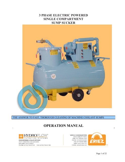
3 PHASE ELECTRIC POWERED<br />
SINGLE COMPARTMENT<br />
SUMP SUCKER<br />
THE ANSWER TO FAST, THOROUGH CLEANING OF MACHINE COOLANT SUMPS<br />
OPERATION MANUAL<br />
Page 1 of 22
TABLE OF CONTENTS<br />
SAFETY INFORMATION..................................................................................3, 4<br />
OPERATOR SAFETY AND CONVENIENCE FEATURES:<br />
Safety Features......................................................................................................5<br />
Convenience Features...........................................................................................5<br />
SUMP CLEANER WARRANTY.....................................................................6, 7, 8<br />
ASSEMBLY...........................................................................................................9<br />
OPERATION ...........................................................................................10, 11, 12<br />
Operating Tips.....................................................................................................13<br />
Proper Machine Cleaning Procedure...................................................................13<br />
Operating Efficiency Tips ..............................................................................13, 14<br />
MAINTENANCE.............................................................................................15, 16<br />
Maintenance Schedule ........................................................................................17<br />
SPARE PARTS LIST .....................................................................................18, 19<br />
SUMP CLEANER TROUBLESHOOTING CHART...................................20, 21, 22<br />
Page 2 of 22
SAFETY INFORMATION<br />
NOTE: SPECIAL SAFETY INFORMATION. TO AVOID POSSIBLE INJURY, BEFORE<br />
OPERATING AN ELECTRICALLY POWERED YELLOW BELLIED SUMP SUCKER, THE<br />
CUSTOMER MUST FURNISH A 4-WIRE, S.O. CORD OF THE PROPER GAUGE FROM<br />
CUSTOMER’S SUPPLY OF POWER AND GROUND TO THE YELLOW BELLIED SUMP<br />
SUCKER CONTROL PANEL. THE GREEN GROUND WIRE MUST BE ATTACHED TO<br />
THE GROUND BAR IN THE YELLOW BELLIED SUMP SUCKER CONTROL PANEL.<br />
CUSTOMER’S GROUND SOURCE MUST BE IN ACCORDANCE WITH ARTICLE 250 OF<br />
THE NATIONAL ELECTRIC CODE (NEC).<br />
1. To avoid possible injury, before operating this cleaner, read this manual for full operating<br />
instructions. Also see the manufacturer’s pump manual provided with<br />
your cleaner.<br />
2. Always block the wheels of the cleaner to prevent unintentional rolling. Even when<br />
empty, some models weigh more than 1,500 pounds. Accidental rolling on sloped<br />
floor, if bumped, could cause injury or property damage.<br />
3. Wear eye goggles to protect your eyes from splashing liquids. This is important,<br />
even when you know the fluids themselves are not caustic or otherwise harmful.<br />
Metal particles suspended in the liquid could still cause serious eye injury.<br />
4. Check hose, nozzle, cleaning tool and hose cap connections for leaks. To minimize<br />
chances of spilling, handle cleaning tools and hoses carefully during operation, and<br />
replace hoses before deterioration results in leaks.<br />
5. Immediately clean up any spilled coolant to avoid slippery floors and dangerous falls.<br />
6. If it is necessary to use the cleaner in an aisle or other traffic area, position it so as<br />
to minimize the likelihood of being struck by trucks, forklifts or other equipment in<br />
transit. Exercise a reasonable lookout for such hazards during operation.<br />
7. Whenever removing or reseating the filter basket (maximum capacity is 800 pounds),<br />
keep hands and fingers out from under the basket lip.<br />
8. Keep clear from beneath the basket when opening the trapdoor and, if necessary,<br />
pull out the contents. Use tools of appropriate strength and length to let you<br />
perform these operations safely.<br />
9. Frequently check the basket’s hoisting rings for signs of rust. If the rings are<br />
heavily corroded, replace the basket with a new one.<br />
10. Be sure the suction inlet ball valve is fully closed before operating the cleaner in<br />
the discharge mode. The tank is pressurized in this mode, sometimes to as much<br />
as 7 PSI<br />
Page 3 of 22
11. DO NOT use this unit for solvents, flammable (low flash point) or other volatile<br />
liquids. Use it only for water-soluble coolants and for cutting or grinding oils.<br />
12. PRESSURIZATION SAFETY ISSUES. Your Yellow Bellied Sump Sucker unit is<br />
designed to operate under pressure when discharging fluids. The optimal safe<br />
operating pressure is 5 to 7 PSI. and your unit was set at the factory to operate in<br />
this range. Your unit should never be operated at pressures in excess of 15 PSI.<br />
Tanks or vessels which are pressurized beyond 15 PSI require special certification<br />
as "High Pressure Vessels" and the Yellow Bellied Sump Sucker has not been<br />
certified for such high pressure operation. Operating a Yellow Bellied Sump <strong>sucker</strong><br />
at pressures above 15 PSI. creates a serious risk of injury to workers and damage<br />
to property.<br />
15. Temperature limit is 150 the limit of the suction and discharge hoses)<br />
16. “Push-around” units (those equipped with large diameter wheels in the middle of<br />
the tank and swivel casters at both ends) are NOT designed for towing. If they<br />
must be moved long distances within a plant, pick up the unit with a forklift truck<br />
using the brackets provided on the <strong>sump</strong> cleaner.<br />
17. This equipment is to be operated and maintained by authorized personnel only.<br />
18. MAGNESIUM CHIPS OR DISSIMILAR METALS. In the presence of water,<br />
magnesium can release hydrogen gas, which is highly flammable and, in the proper proportions<br />
with air, can be explosive. When a Yellow Bellied Sump Sucker is used on<br />
a metalworking fluid application generating magnesium chips, certain precautions must<br />
be taken to ensure that any hydrogen gas is dissipated into the atmosphere and to make<br />
sure the hydrogen does not accumulate in the Yellow Bellied Sump Sucker. This is<br />
accomplished by promptly removing any magnesium chips from the <strong>sump</strong> <strong>sucker</strong> basket.<br />
Also, a maintenance schedule should be established by the customer that would eliminate<br />
buildup of sludge in the bottom of the Yellow Bellied Sump Sucker. Finally, the unit<br />
should be stored in a clean condition with basket empty of chips, the <strong>sump</strong> cleaner tower<br />
lid removed, the coolant discharge nozzle(s) removed and hoses open to atmosphere (on<br />
<strong>single</strong> and twin <strong>compartment</strong> units). Taking these precautions will minimize the risk of<br />
hydrogen gas generation and accumulation.<br />
On an application where dissimilar metals are machined, there is a chance for<br />
spontaneous combustion to occur. Typically, metalworking facilities that machine<br />
various metals are aware of this and may have experienced problems in chip<br />
hoppers due to the presence of two of more metals, water, and tramp oil.<br />
The precautions mentioned in the previous paragraph will minimize or eliminate the<br />
potential for spontaneous combustion.<br />
19. The cleaner is to be adjusted and/or repaired only by qualified service personnel. If<br />
These personnel need more information than is provided in this manual, they should contact:<br />
Eriez Hydroflow - 419-794-2102<br />
Page 4 of 22
OPERATOR SAFETY AND CONVENIENCE FEATURES<br />
Safety Features<br />
Although <strong>sump</strong> cleaners are inherently safe machines, they pose the potential for hand and finger injury when<br />
the operator has to remove the filter basket from the unit to empty it of chips and sludge. For this reason, The<br />
Andersons has two safety features which are unique to “Yellow Bellied Sump Suckers”.<br />
Filter basket safety guides automatically center the filter basket within the unit’s basket support tower as it is<br />
being hoisted out of the machine. This eliminates the need for the operator to physically guide the heavy, full<br />
basket as it is being elevated and significantly reduces the opportunity for the operator to receive hand injuries.<br />
Basket “trapdoor” release cables enable the operator to empty the filter basket (the basket can hold up to 800<br />
pounds of chips) from a safe distance without the need for special tools. The basket is removed from the unit,<br />
positioned over a chip hopper or similar receptacle and the contents are released through the basket bottom by<br />
the operator opening the trapdoor with a sharp pull on the release cable. During the entire operation, the<br />
operator is a safe distance away.<br />
Convenience Features<br />
Low rolling resistance, high maneuverability design: Yellow Bellied Sump Suckers feature high<br />
impact, fiber reinforced, hard plastic casters and wheels for low rolling resistance, whether the unit is<br />
empty or full. The standard wheel configuration places the main wheels in the unit’s middle and<br />
swivel casters on each end for high maneuverability; a Yellow Bellied Sump Sucker pivots within its<br />
own length while “tricycle gear” units swing in double their length.<br />
Clamped basket lids make lid removal and replacement much faster and easier than it is with the screw<br />
clamps used on other makes of <strong>sump</strong> cleaners.<br />
External, leak-proof, round cleanout doors are faster and easier to remove and replace than the oval,<br />
internal “manholes” used by other manufacturers. The thick, pliable gasket bonded to the cleanout<br />
door virtually eliminates leaks.<br />
Forklift truck brackets are standard on all “push-around” Yellow Bellied Sump Suckers so that the unit<br />
can be safely and easily picked up and moved long distances. (Standard design units are not intended<br />
to be towed; special wheel designs are available at extra cost for units which the customer desires to<br />
tow.)<br />
Smooth radius basket suction inlet virtually eliminates suction hose “chip jams”.<br />
Float switch overfill protection virtually eliminates pump damage and coolant spills by automatically<br />
shutting down the <strong>sump</strong> cleaner’s motor when the tank is full.<br />
Page 5 of 22
SUMP CLEANER WARRANTY<br />
Eriez Hydroflow warrants to the original purchaser, as hereinafter defined, all <strong>sump</strong> cleaners described<br />
below and parts thereof, other than gaskets, hoses, filter basket sleeves, cleaning tools, wheels, casters<br />
and batteries which are specifically excluded from this warranty, to be free from defects in material<br />
and/or workmanship under normal use and service for a period of one (1) year from date of invoice of<br />
said equipment to the original purchaser. For the period of this warranty, Eriez Hydroflow agrees to<br />
repair or replace, at its option, with similar part or parts, any part or parts of said equipment which<br />
have failed due to defects in factory workmanship and/or faulty material. Any repairs or replacement<br />
under this warranty shall be provided without cost to the original purchaser except as noted hereinafter<br />
provided.<br />
Eriez Hydroflow shall not be responsible for any expenses incurred for service or repairs performed by<br />
any person or persons other than Eriez Hydroflow, unless specifically authorized by Eriez Hydroflow.<br />
Eriez Hydroflow shall not be liable for repairs or replacement of any parts missing or damaged due to<br />
service or repairs performed by any person or persons other than Eriez Hydroflow, unless specifically<br />
authorized by Eriez Hydroflow. Service calls for repair of equipment within the first ninety (90) days<br />
of this warranty will be at the expense of Eriez Hydroflow. Service calls for the repair of equipment<br />
after the first ninety (90) days of this warranty will be at the expense of the original purchaser.<br />
Expenses for service calls shall include, but not be limited to, reasonable travel, food and lodging<br />
expenses.<br />
Notwithstanding the foregoing, replacement of the suction/discharge pump shall be made by Eriez<br />
Hydroflow without cost to the original purchaser only after return of the suction/discharge pump to<br />
Eriez Hydroflow by the original purchaser; freight prepaid. If upon examination by Eriez Hydroflow<br />
or its authorized representatives, it appears that the suction/discharge pump was defective, Eriez<br />
Hydroflow shall replace the suction/discharge pump without cost to the original purchaser, except for<br />
freight.<br />
All of Eriez Hydroflow obligations pursuant to this warranty are subject to the following additional<br />
restrictions, limitations and exceptions.<br />
1. Gasoline and LP Gas internal combustion engines are not covered by this<br />
warranty, but rather are covered by the standard warranty of the engine<br />
manufacturer, which varies from model to model. Copies of the specific warranty of the<br />
manufacturer will be shipped with the unit and such warranties and limitations are incorporated<br />
by reference herein. Upon request, copies of the engine manufacturer’s warranty will be<br />
provided in advance of shipment.<br />
Page 6 of 22
2. For units mounted on mobile platforms or other similar sub-assemblies, such as<br />
trucks, carts, or self-propelled platforms, Eriez Hydroflow makes no warranties for such subassemblies<br />
manufactured by third parties and specifically disclaims any warranties with regard<br />
thereto, including implied warranties of merchantability or fitness for a particular use. The only<br />
warranties as to such sub-assemblies are those extended to purchaser directly by the third-party<br />
manufacturer, and such warranties are subject to all of the terms, conditions, and limitations of<br />
the third party’s warranties and are enforceable only against said third-party manufacturer; and<br />
Eriez Hydroflow is not underwriting or guaranteeing their warranties, nor is Eriez Hydroflow an<br />
agent of said third-party manufacturers for purpose of pursuing warranty claims or making<br />
service arrangements or any other purpose. Copies of such third-party sub-assembly<br />
manufacturers’ specific warranty information will be shipped with the unit, and such warranties<br />
and limitations are incorporated by reference herein. Upon request, copies of sub-assembly<br />
manufacturers’ warranty information will be provided in advance of ordering or shipment.<br />
3. On all units, including Yellow Bellied Sump Suckers and other <strong>sump</strong> cleaning<br />
equipment, all wheels, casters and batteries are considered expendable or<br />
ordinary maintenance items and are expressly exempted from this warranty and<br />
are not covered by any other warranty, express or implied. THE WARRANTIES<br />
DESCRIBED IN THE ABOVE PARAGRAPHS SHALL BE IN LIEUOF ANY OTHER<br />
WARRANTIES, EXPRESSED OR IMPLIED, INCLUDING BUT NOT LIMITED TO ANY<br />
IMPLIED WARRANTY OF MERCHANTABILITY OR FITNESS FOR A PARTICULAR<br />
PURPOSE. ERIEZ HYDROFLOW SHALL NOT, IN ANY EVENT, BE LIABLE FOR<br />
INCIDENTAL OR CONSQUENTIAL DAMAGES; AND TOTAL LIABILITY OF THE<br />
ANDERSONS SHALL NOT EXCEED THE COST OF REPAIRING OR REPLACING THE<br />
COVERED GOODS OR EQUIPMENT. NOT WITHSTANING ANY PROVISION OR<br />
PURCHASER’S PURCHASE ORDERS OR OTHER CONTRACT DOCUMENTS,<br />
ACCEPTANCE AND USE OF THE ANDERSONS PRODUCTS BY PURCHASER<br />
CONSTITUTES ACCEPTANCE OF THESE LIMITATIONS OF ERIEZ HYDROFLOW<br />
LIABILITY AND WARANTIES.<br />
This warranty neither assumes or authorizes any other person to assume for<br />
Eriez Hydroflow any other liability in connection with the equipment manufactured<br />
by Eriez Hydroflow. This warranty applies only within the boundaries of the United<br />
States of America, its territories and possessions, and Canada. This warranty is<br />
not assignable.<br />
Original purchaser as used herein, shall mean only such person, persons,<br />
association or corporation which purchase the equipment hereinafter described for<br />
actual use.<br />
Page 7 of 22
This warranty does not apply to damage of any unit occurring in transit, caused<br />
by alteration by unauthorized persons, fire, accident, artificially generated <strong>electric</strong><br />
current, acts of God, misuse or abuse, or any other cause whatsoever other than<br />
defects in factory workmanship and/or material.<br />
The Andersons shall not be liable for any damage to or loss of any cutting fluids or<br />
for loss of any income or profits due to the malfunctioning of the equipment hereinafter<br />
described, whether the malfunctioning is caused by defects in factory workmanship<br />
and/or faulty material, or any other cause whatsoever.<br />
Component parts returned for replacement must show the original unit serial number from which<br />
they were removed. Parts returned without the aforementioned<br />
serial number will be replaced at established replacement prices. This warranty<br />
does not cover equipment damaged by misuse, negligence or accident.<br />
Vacuum and pressure relief valves are preset at the factory. ALTERATION OF<br />
THE SETTINGS EXCEPT WITH THE SPECIFIC AUTHORIZATION OF ERIEZ<br />
HYDROFLOW OR ITS AUTHORIZED REPRESENTATIVES WILL VOID THIS<br />
WARRANTY.<br />
Page 8 of 22
ASSEMBLY<br />
1. Refer to the drawings at the end of this manual for location of the items discussed<br />
below and the following sections of this manual.<br />
2. Remove the cover of the basket. Keep hands and fingers from under the filter basket<br />
gasket. Take out the following items:<br />
A. filter basket (factory assembled with sleeve)<br />
B. discharge hose with nozzle<br />
C. suction hose<br />
D. cleaning tool<br />
E. spare filter sleeve or filter bags<br />
3. Check the locking pin that holds the filter basket’s trapdoor shut. Make sure it is<br />
securely in place (fully extended as shown in drawing at the end of the manual).<br />
4. Keeping hands and fingers from under the basket lip, reseat the filter basket in the<br />
tank. Replace the tank lid and clamp it down.<br />
5. Attach the suction hose to the intake connection on the tank lid. Attach the cleaning<br />
tool to this hose, then coil the hose around the push handle or hose hangers provided<br />
at the basket end of the tank. Place cleaning tool in pipe holder attached to the side of<br />
the tank<br />
6. Couple the discharge hose to the discharge connection on the side of the tank and coil it<br />
over the push handle or hose hangers provided.<br />
Page 9 of 22
OPERATION<br />
1. Before operating this equipment for the first time, and periodically thereafter, review<br />
the SAFETY INFORMATION beginning on Page one of this manual<br />
2. Connect the cleaner to the <strong>electric</strong> supply specified on the control panel.<br />
A. Correct phasing of the <strong>electric</strong> supply outlets is essential. The <strong>sump</strong> cleaner’s<br />
motor runs in one direction to perform the suction operation and in the opposite<br />
direction for discharge. The float switch in the suction cycle relay holding<br />
circuit causes this circuit to drop out at a predetermined liquid level in the tank,<br />
preventing overfilling and pump dam age. The discharge circuit has no such<br />
float switch, therefore, the cleaner must be plugged into outlets that are<br />
uniformly <strong>phase</strong>d, so that operating the SUCTION button rotates the motor and<br />
pump in the correct direction. Connection to improperly <strong>phase</strong>d outlets can void<br />
the warranty on this machine.<br />
B. Test the outlet phasing by pushing the SUCTION button and verifying whether<br />
the cleaning tool is actually sucking. If not, the outlet phasing must be modified<br />
by authorized service personnel.<br />
3. For suction operation: Open the inlet ball valve fully, press the SUCTION button<br />
to start the motor and vacuum coolant and chips from the <strong>sump</strong>.<br />
Page 10 of 22
4. As soon as fluid stops passing through the hose, press the STOP button to turn off the<br />
motor. A. The <strong>compartment</strong>’s maximum capacity is, at most, 10% above the rated<br />
capacity. The float switch described in Paragraphs 3 and 4 above, and located near the<br />
<strong>compartment</strong> suction fitting, will shut off the motor if overfilling starts to occur. If this<br />
should happen, follow instructions for the discharge operation in Paragraph 7 below.<br />
5. To return filtered chip-free coolant to the <strong>sump</strong>, or wash down the machine, or<br />
discharge dirty coolant into your recycling or disposal system, close the suction inlet<br />
ball valve. Push the DISCHARGE button and depress the discharge hose nozzle valve.<br />
A. Be sure the suction inlet ball valve is fully closed before operating in the<br />
DISCHARGE mode!<br />
B. IMPORTANT! Be sure the suction inlet ball valve is fully closed or fully open,<br />
depending on the desired operation (closed-discharge, open-suction). Failure to<br />
do so will allow particulates to enter the valve seat and seize the valve.<br />
6. Stop the motor as soon as fluid stops passing through the hose.<br />
A. The cleaner is to be adjusted and/or repaired only by qualified service<br />
personnel. If these personnel need more information than is provided in this<br />
manual, they should contact The Andersons at 419-891-2724<br />
B. The <strong>sump</strong> cleaner will discharge all but about an inch of fluid in the bottom of<br />
the <strong>compartment</strong>. This is unimportant if the <strong>compartment</strong> cleaner is used for one<br />
type of coolant only. If different coolants are to be handled in that <strong>compartment</strong>,<br />
remove its drain plug to empty it completely.<br />
7. To empty the filter basket:<br />
A. Remove tower lid.<br />
B. Attach lifting device to basket rings. CAUTION: All components used to lift<br />
basket (steel cable, hooks, crane, etc.) must have a minimum capacity of 1000<br />
pounds.<br />
C. To avoid the basket binding in the tower during removal, position the lifting<br />
power source (e.g. crane) directly over the center of the basket.<br />
Page 11 of 22
D. Hoist the basket. Keep hands and fingers clear. If the basket is not exiting the<br />
center of the tower, return (lower) basket to the <strong>sump</strong> cleaner tower. Reposition<br />
the lifting device so that the basket exits the center of the tower.<br />
E. DO NOT TOUCH BASKET DURING REMOVAL.<br />
F. Position the basket over the waste receptacle.<br />
G. Standing clear, open the basket trapdoor by pulling the locking pin cable.<br />
8. Once the basket is empty, carefully close the trapdoor and slide the locking pin into<br />
place.<br />
9. Check the filter sleeve. If it is badly soiled or clogged, turn it inside out and wash it in<br />
a suitable cleaner. Replace filter when necessary. (MAINTENANCE section of this<br />
manual.)<br />
10. Inspect the basket hoisting rings for signs of rust. Replace the basket with a new one if<br />
the rings are heavily corroded.<br />
11. Keeping hands and fingers from under the basket lip, reseat the basket in the tank and<br />
lamp down the tank lid.<br />
Page 12 of 22
OPERATING TIPS<br />
Yellow Bellied Sump Suckers have been designed to make the job of proper machine tool coolant<br />
<strong>sump</strong> cleaning as easy as possible for the operator of the <strong>sump</strong> <strong>sucker</strong>. They have the power necessary<br />
for true, high-performance <strong>sump</strong> cleaning; they will vacuum from the <strong>sump</strong> anything that will pass<br />
through its two inch diameter suction hose and it will suck up water soluble coolant at nearly 100<br />
gallons per minute. At the same time, all Yellow Bellied Sump Suckers are designed with operator<br />
safety and ease of operation and maintenance as foremost considerations.<br />
Although the units are designed for operator safety, before using the <strong>sump</strong> <strong>sucker</strong> for the first time<br />
(and periodically thereafter for a review), read the section of this Operator’s Manual entitled “Safety<br />
Information”, pages 1-2<br />
Proper Machine Cleaning Procedure<br />
Your <strong>Master</strong> Chemical Fluid District Manager has been especially trained in machine cleaning<br />
techniques and is available to help point out potential problem areas where hidden sludge deposits can<br />
accumulate in your machines. Feel free to call on him for assistance.<br />
Operating Efficiency Tips<br />
Here are some tips to improve the operating efficiency of your <strong>sump</strong> <strong>sucker</strong>:<br />
• Follow the <strong>sump</strong> <strong>sucker</strong>’s maintenance schedule carefully. Preventive maintenance is<br />
far less expensive than major repairs.<br />
• Clean your <strong>sump</strong> <strong>sucker</strong> (or just the filter tank of a twin <strong>compartment</strong> unit) about once<br />
a month or whenever sludge or fines have become noticeable in the bottom of the tank.<br />
• Rinse the unit with plain water and drain it completely by removing the drain plug<br />
whenever changing from one brand or type of coolant to another; there can be<br />
compatibility problems with some products, so avoid contamination. (Remember to<br />
replace the plug.)<br />
• It is better to have one <strong>sump</strong> <strong>sucker</strong> for use with water soluble coolants and another for<br />
use with cutting oils. If you must use one unit for both, the <strong>sump</strong> <strong>sucker</strong> must be<br />
thoroughly cleaned when switching products. If at all possible, purchase a filter basket<br />
and a set of hoses for each product. (The <strong>sump</strong> <strong>sucker</strong> tank is not too hard to clean, but<br />
the hoses and filter basket are.) Organize your machine pumping schedule so that during<br />
one week you are pumping machines running water solubles and the next week you are<br />
pumping machines running cutting oils; this minimizes cleaning the <strong>sump</strong> <strong>sucker</strong>.<br />
Page 13 of 22
• When vacuuming out machines using water soluble coolants, put the cleaning tool on<br />
the bottom of the <strong>sump</strong> and remove coolant and chips together.<br />
• When vacuuming out machines using cutting or grinding oil, remove the oil first and<br />
then vacuum up the chips and fines.<br />
• Do NOT alter the unit’s vacuum relief valve settings. You will not improve your <strong>sump</strong><br />
<strong>sucker</strong>’s performance and you will void its warranty.<br />
• Do NOT use your unit for solvents, volatile or low flash point fluids of any type. It is<br />
designed for use with coolants, cutting oils, water soluble machine cleaning solutions<br />
and parts washing compounds only.<br />
• When pumping out of floor pits you can increase the efficiency by drilling a 1/4" hole<br />
in the cleaning tool below where the hose is attached. By keeping this hole above the<br />
fluid level, you allow more air to enter the hose which helps move the fluid up the hose<br />
faster and possibly allow pumping out of deeper pits. If you have any questions about<br />
your unit or its suitability for a particular job, please contact your <strong>Master</strong> Chemical<br />
(TRIM® coolant) distributor, your <strong>Master</strong> Chemical District Manager or Eriez Hydroflow.<br />
Page 14 of 22
MAINTENANCE<br />
1. Check the filter basket’s polypropylene mesh filter sleeve frequently. If it is badly soiled or<br />
clogged, remove the retaining ring beneath the lifting rings, and take off the gasket snugged<br />
over the basket’s top ring. Lift out the sleeve, turn it inside out and wash it in a suitable<br />
cleaner.<br />
2. If the filter sleeve is torn, or if it is soiled or clogged to the point where simple cleaning is<br />
inadequate, replace the sleeve with a new one (P/N 60-1460).<br />
3. To install a new sleeve: With the basket gasket and retaining ring removed; fit the sleeve inside<br />
the basket. Fold the top edge out over the basket’s top ring, and snug down the gasket to hold<br />
the sleeve in place. Make two small holes in the sleeve over the basket’s lifting rings. Pull the<br />
rings through. Fit the retaining ring into the basket beneath the lifting rings and tighten it out<br />
securely against the basket.<br />
Figure III-A<br />
Retaining Ring<br />
Top Gasket<br />
4. Frequently check the basket lifting rings for signs of rust. If the rings become badly corroded,<br />
replace the basket with a new one.<br />
Page 15 of 22
5. If the filter sleeve is maintained in good condition, only fine particles should normally settle<br />
out in the bottom of the tank. Remove these periodically by opening the drain plug and with<br />
the filter basket out of the <strong>sump</strong> cleaner, flush the tank with a water hose.<br />
6. Periodically, while the basket is out of the tank, check the tank interior for sludge buildup. If<br />
such a buildup starts to thicken, use an appropriate tool to scrape it off the tank walls and out of<br />
the cleanout door.<br />
7. Periodically check the pump oil level. Fill if required. (See the manufacturer’s pump<br />
Manual provided with your cleaner.)<br />
8. Grease the pump bearings (FIGURE III-D) at least every three months. For type of<br />
lubricant, see the recommendations in the manufacturer’s pump manual provided with this<br />
equipment.<br />
FIGURE III-D<br />
9. Periodically check the engine oil level. Fill if required (see manufacturer’s engine<br />
manual provided with your cleaner).<br />
10. Periodically, check hoses for deterioration and replace with new ones if leaks have<br />
developed or appear imminent. Always coil hoses properly over the supports provided<br />
when not in use.<br />
11. Other than the routine maintenance operations specified above, adjustments and/or<br />
repairs to this equipment should be undertaken only by authorized service personnel. If<br />
these personnel need more information than is provided in this manual, they should<br />
contact Eriez Hydroflow, Maumee, OH – 419-794-2102.<br />
Page 16 of 22
W<br />
E<br />
E<br />
K<br />
L<br />
Y<br />
M<br />
O<br />
N<br />
T<br />
H<br />
L<br />
Y<br />
6<br />
M<br />
O<br />
N<br />
T<br />
H<br />
S<br />
1<br />
2<br />
M<br />
O<br />
N<br />
T<br />
H<br />
S<br />
MAINTENANCE<br />
SCHEDULE FOR ELECTRIC<br />
MOTOR YELLOW BELLIED<br />
SUMP SUCKERS<br />
INSPECT SUCTION &<br />
DISCHARGE HOSES;<br />
REPLACE AS NEEDED<br />
INSPECT FILTER BASKET<br />
SLEEVE; REPLACE AS<br />
NEEDED; INSPECT BASKET<br />
LIFTING RINGS FOR<br />
CORROSION<br />
INSPECT TANK FOR SLUDGE<br />
BUILDUP; CLEAN AS<br />
NEEDED<br />
CHECK BLOWER OIL LEVEL;<br />
ADD SAE-40 NON-<br />
DETERGENT OIL AS NEEDED<br />
GREASE BLOWER; USE NO.2<br />
BEARING GREASE (500<br />
HOURS)<br />
GREASE MOTOR BEARINGS<br />
(BEARING GREASE)<br />
GREASE WHEELS &<br />
CASTERS; USE NO.2<br />
BEARING GREASE<br />
CHANGE BLOWER OIL; USE<br />
SAE-40 NONDETERGENT OIL<br />
(1500 HOURS)<br />
DRAIN BLOWER MUFFLERS<br />
(DRAIN PLUG IS ON LOWER<br />
END OF MUFFLER) IF<br />
EQUIPPED WITH OPTIONAL<br />
SOUND REDUCTION<br />
MUFFLERS<br />
MAINTENANCE LOG<br />
Date placed into service:<br />
______________<br />
Record date of service below:<br />
_______________<br />
Page 17 of 22
SPARE PARTS LIST<br />
PART NO DESCRIPTION NOTES<br />
54-1040 3MR Vertical Air Blower<br />
54-1080 4MR Vertical Air Blower<br />
38-1120 3” Float switch N/C Need serial number to order<br />
38-1140 Gems Float switch Need serial number to order<br />
38-1180 3” Float switch assembly N/C Need serial number to order<br />
55-1160 3/4” Coupling half For 3MR blower<br />
55-1180 1 1/8” coupling half For 5 HP motor<br />
55-1200 Coupling Insert For 5HP/3MR<br />
55-1220 7/8” Coupling half For 4MR blower<br />
55-1240 1 3/8” Coupling half For 10 HP motor<br />
55-1260 Coupling Insert For 10 HP/4MR<br />
41-2110 2” Orange Suction Hose Sold by the foot<br />
41-2090 1-1/2” Orange Discharge Hose Sold by the foot<br />
42-1140 1-1/2” Male QD X Hose Shank<br />
42-1200 1-1/2” Fem QD X 1” Fem NPT<br />
42-1220 1-1/2” hose barb<br />
42-0133 2” Fem QD X Barb<br />
42-0132 2” Male QD X Male NPT<br />
60-1960 1” NPT Discharge Nozzle (Also see assemblies)<br />
60-1500 Manhole/Cleanout Gasket-oval 11” x 15” SN – 1000-3311<br />
60-1520 Manhole/Cleanout Gasket–Round 14-1/4” Dia. SN – 3322 to Present<br />
60-1560 Top Gasket - Basket<br />
60-1140 Basket Retaining Ring<br />
60-1480 Paper Filter Bag<br />
60-1460 Poly Filter Sleeve<br />
43-1060 Swivel Caster - 4” Dia. X 2”Wide<br />
43-1220 Wheel – 12” Dia. x 3”Wide x 1” bearing SN 1000-3456<br />
43-1240 Wheel - 12” Dia. x 3”Wide x 1-1/4” bearing SN 3457 to Present<br />
24-1020 1” NPT Pressure Relief Valve<br />
24-1040 1” Vacuum Relief valve<br />
60-1260 18” Suction Tool - 2” Diameter<br />
60-1220 36” Suction Tool - 2” Diameter<br />
60-1360 36” Crevice Tool - 2” Diameter<br />
60-1800 18” Electric Muffler Set assembly Both intake and exhaust mufflers<br />
60-1880 18” Electric intake muffler assembly<br />
60-1840 18” Electric exhaust muffler assembly<br />
60-1980 1” Discharge Nozzle Assembly<br />
60-1100 24” Sludge Basket Assembly Used on 100 gallon tanks<br />
60-1080 36” Sludge Basket Assembly<br />
Page 18 of 22
OPTIONAL EQUIPMENT - SUMP SUCKER:<br />
PART NO DESCRIPTION<br />
Spare Parts for Truck Mounted Rectangular Sump Cleaner (S/N 3346 on):<br />
60-1540 Cleanout Gasket 3/8” x 15” x 21” (rectangular)<br />
Spare Parts For Tow Around Sump Cleaner<br />
43-1140 Wheel/Caster - 8” diameter x 3” wide rigid (400 total gallons or less)<br />
43-1160 Wheel/Caster - 8” diameter x 3” wide swivel (400 total gallons or less)<br />
43-1180 Wheel/Caster - 10” diameter x 4” wide rigid (500 total gallons or more)<br />
Page 19 of 22
SUMP CLEANER TROUBLESHOOTING CHART<br />
PROBLEM PART TO CHECK POSSIBLE SOLUTION<br />
Does not start/does not run 1. Fuses 1. Check fuses in control panel; replace as needed<br />
2. Motor Heaters 2. Check motor starter heaters, reset if tripped<br />
3. Power supply 3. On LP units, check for dead battery; on <strong>electric</strong><br />
units, ensure plug is fully seated in wall outlet of<br />
the proper voltage<br />
4. Gas bottle 4. On LP units, make sure gas bottle is not empty,<br />
that bottle valve is fully open and that hose is tight<br />
5. Float 5. Ensure that float is unobstructed and operating; if<br />
tank is full, float switch will not allow unit to start;<br />
switch to discharge mode<br />
6. Air cleaner 6. On engine-driven units, make sure air cleaner<br />
element is clean; clean or replace as needed<br />
7. Fuelock filter/ 7A. On LP units, faulty fuelock filter or regulator;<br />
Regulator repair or replace<br />
7B. Check o-ring for wear on valve operating pin<br />
inside fuelock filter; replace<br />
8. Vacuum Leak 8. Check vacuum hose and fittings for leaks<br />
Insufficient suction or 1. Basket 1A. Check for full basket; empty<br />
no suction 1B. Check if basket liner is blinded off, clean or<br />
replace<br />
2. Hoses 2A. Check for obstructions; physically remove<br />
2B. Check for cracks or holes: replace<br />
3. Air leakage 3. Check all hose connections for tightness; check<br />
that discharge ports on filter basket and repair or<br />
replace<br />
4. Regulator 4. Vacuum regulator could be out of adjustment;<br />
Contact a Service Technician at the Andersons,<br />
Systems Equipment Division<br />
5. Discharge nozzle 5. Check that discharge nozzle is fully closed and in<br />
Place<br />
6. Pneumatic muffler 6. Ensure pneumatic muffler is not covered with<br />
Dirt/oils; clean or replace clean or replace<br />
7. Blower Mufflers 7. Check blower mufflers for oil and coolant first<br />
Plugging: replace<br />
8. Air pressure regulator 8. Check supply air pressure setting; adjust<br />
9. Air supply 9. Check air supply pressure, 90 PSI needed, check<br />
Air supply hose diameter, ½” required<br />
10. Air venturi silencer 10. Check silencer on air venturi power head for<br />
Blockage by dirt/oil; clean or replace<br />
Page 20 of 22
PROBLEM PART TO CHECK POSSIBLE SOLUTION<br />
Insufficient discharge 1. Suction valve 1. Check that suction inlet ball valve is fully closed<br />
pressure<br />
2. Regulator 2. Pressure regulator could be out of adjustment;<br />
contact a Service Technician at The<br />
Andersons, Systems Equipment Division<br />
Will not discharge 1. Discharge standpipe 1. Check standpipe for blockage; physically remove<br />
obstruction<br />
2. Discharge hose 2. Check hose for blockage; physically remove<br />
obstruction<br />
3. Tank 3. Check for build up of fines and swarf in bottom of<br />
tank; clean as necessary<br />
4. Pneumatic Muffler 4. Ensure pneumatic muffler is not covered by dirt/<br />
/oil; clean or replace<br />
5. Discharge nozzle 5. Check to see if nozzle is plugged, physically<br />
remove obstruction<br />
6. 4 Way Valve 6. Be sure 4 way valve is in discharge position<br />
7. Suction Valve 7. Be sure suction inlet ball valve is fully closed<br />
Fluid dripping from exhaust 1. Float 1A. Ensure that <strong>electric</strong> float is unobstructed and<br />
mufflers operating<br />
1B. Damaged float ball: replace<br />
2. Discharge ports 2. Check that all discharge ports are fully closed<br />
or capped<br />
3. Discharge Nozzle 3. Be sure discharge nozzle is fully closed<br />
4. Tank selector switch 3. On dual <strong>compartment</strong> units, ensure switch is set<br />
for tank in use; improper switch setting will not<br />
enable float switch to work<br />
4. Foam 4. Check for excessive coolant foaming; call coolant<br />
supplier for corrective action<br />
5. Air venturi silencer 5. If fluid drips from air venturi silencer on air units,<br />
check mechanical float assembly for dirt/<br />
particulate around sealing surface of ball<br />
Page 21 of 22
PROBLEM PART TO CHECK POSSIBLE SOLUTION<br />
Engine stalls during discharge 1. Engine 1. Check engine RPM; adjust as necessary<br />
or suction<br />
2. Regulator 2. Pressure or vacuum regulator could be out of<br />
adjustment; contact a Service Technician at<br />
The Andersons, Systems Equipment Division<br />
3. Pneumatic Muffler 3. Ensure pneumatic muffler is not covered with<br />
dirt/oils; clean or replace<br />
4. LP system 5. Check if LP system is frozen or not<br />
working correctly, repair or replace<br />
Excessive Noise 1. Blower 1. Blower rotors are out of time and knock; replace<br />
2. Blower muffler 2A. Check muffler for rust out or holes; replace<br />
2B. Check mufflers for liquid saturation; drain and dry<br />
or replace<br />
3. Pneumatic muffler 3. Check to see if pneumatic muffler is rusted out,<br />
replace<br />
4. Engine Muffler 4. Check to see if engine muffler is rusted out;<br />
replace<br />
5. RPM’s too high 5. Check engine RPM for proper speed;<br />
adjust engine<br />
6. Air Venturi silencer 6. Check for liquid saturation; drain and dry or<br />
replace<br />
Portability 1. Hard to push 1A. Check for worn wheels or casters; replace<br />
1B. Check wheel and caster bearings: grease or<br />
replace<br />
1C. Rough Floors: investigate a tow unit or use a<br />
forklift to transport<br />
ALWAYS CHECK YOUR MANUAL FOR OPERATION INSTRUCTIONS AND MAINTENANCE<br />
This unit Supplied by<br />
Page 22 of 22