TRAFFIC CONTROL TELEPHONE SYSTEMS Circuit - Sam Hallas
TRAFFIC CONTROL TELEPHONE SYSTEMS Circuit - Sam Hallas
TRAFFIC CONTROL TELEPHONE SYSTEMS Circuit - Sam Hallas
Create successful ePaper yourself
Turn your PDF publications into a flip-book with our unique Google optimized e-Paper software.
Page 30<br />
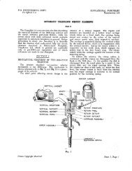
(c) The total travel of the stepping pawl (U) shall not be less than 1¾ nor more<br />
than two teeth of the ratchet wheel (W).<br />
(d) The movement at the end of the stepping pawl (U) shall be such that it will<br />
obtain full engagement with the teeth on the ratchet wheel (W) at all times.<br />
(e) The holding pawl (Q) shall fall reliably into each tooth of the ratchet wheel<br />
(W) as it is advanced by the stepping pawl (U) with a maximum backlash of<br />
0.005 inch.<br />
Holding Spring and Code Wheel<br />
(a) When the code wheel (E) is revolved by hand the cup-shaped part of the<br />
holding spring (K) shall clear the inside of the code pins (C) and time arm by<br />
not less than 0.005 inch, and shall clear the lower surface of the enlarged part<br />
of the code pins and nuts by not less than 0.015 inch.<br />
(b) When the code wheel (E) is advanced by the armature (O) the holding spring<br />
(K) shall clear the code pins (C) and the time arm in its outward motion by<br />
not less than 0.005 inch.<br />
(c) The code wheel (E) and code pins (C) shall be located so that after each<br />
group of impulses in its own particular code the holding spring (K) shall, on<br />
the release of the armature (O), engage with each code pin in turn so that the<br />
pin is held in the cup and retains the code wheel in that position until advanced<br />
by the next group of impulses or the releasing impulse. The holding<br />
spring (K) in normal position shall press against the insulating stud on the<br />
rocker arm (S) with a pressure of 1 gramme minimum to 3 grammes maximum.<br />
(d) The holding spring (K) shall be adjusted to lie flat along the whole length of<br />
the buffer and the tension against the buffer measured at the end of the buffer<br />
shall not exceed 10 grams.<br />
(e) Altering the Selector from 17 to 27 Step Code. To change the setting from 17<br />
to the 27 step code, loosen slightly the two code wheel screws (F) holding the<br />
code wheel (E) on the shaft. Step the ratchet wheel (W), by operating the<br />
armature (O) by hand, to the 27th step and hold it. Then rotate the code<br />
wheel on the shaft so that the contact spring makes contact with the first<br />
ringing terminal and the permanent code pin will be in position to be engaged<br />
by the holding spring (K). Tighten firmly the two code wheel screws (F).<br />
Contact Spring<br />
(a) When the selector is mounted in a horizontal position or in a vertical position<br />
with the armature (O) at the bottom, the contact spring (Z) shall be<br />
raised by the ringing terminals by not less than 0.02 inch when in the ringing<br />
position.


