H-4 CONTROLAIR VALVE - Bosch Rexroth
H-4 CONTROLAIR VALVE - Bosch Rexroth
H-4 CONTROLAIR VALVE - Bosch Rexroth

You also want an ePaper? Increase the reach of your titles
YUMPU automatically turns print PDFs into web optimized ePapers that Google loves.
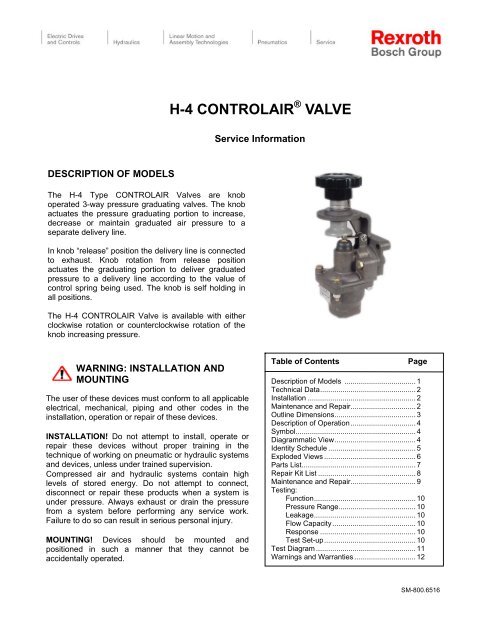
DESCRIPTION OF MODELS<br />
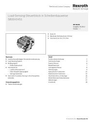
The H-4 Type <strong>CONTROLAIR</strong> Valves are knob<br />
operated 3-way pressure graduating valves. The knob<br />
actuates the pressure graduating portion to increase,<br />
decrease or maintain graduated air pressure to a<br />
separate delivery line.<br />
In knob “release” position the delivery line is connected<br />
to exhaust. Knob rotation from release position<br />
actuates the graduating portion to deliver graduated<br />
pressure to a delivery line according to the value of<br />
control spring being used. The knob is self holding in<br />
all positions.<br />
The H-4 <strong>CONTROLAIR</strong> Valve is available with either<br />
clockwise rotation or counterclockwise rotation of the<br />
knob increasing pressure.<br />
WARNING: INSTALLATION AND<br />
MOUNTING<br />
The user of these devices must conform to all applicable<br />
electrical, mechanical, piping and other codes in the<br />
installation, operation or repair of these devices.<br />
INSTALLATION! Do not attempt to install, operate or<br />
repair these devices without proper training in the<br />
technique of working on pneumatic or hydraulic systems<br />
and devices, unless under trained supervision.<br />
Compressed air and hydraulic systems contain high<br />
levels of stored energy. Do not attempt to connect,<br />
disconnect or repair these products when a system is<br />
under pressure. Always exhaust or drain the pressure<br />
from a system before performing any service work.<br />
Failure to do so can result in serious personal injury.<br />
MOUNTING! Devices should be mounted and<br />
positioned in such a manner that they cannot be<br />
accidentally operated.<br />
H-4 <strong>CONTROLAIR</strong> ® <strong>VALVE</strong><br />
Service Information<br />
Table of Contents Page<br />
Description of Models ................................... 1<br />
Technical Data............................................... 2<br />
Installation ..................................................... 2<br />
Maintenance and Repair................................ 2<br />
Outline Dimensions........................................ 3<br />
Description of Operation................................ 4<br />
Symbol........................................................... 4<br />
Diagrammatic View........................................ 4<br />
Identity Schedule ........................................... 5<br />
Exploded Views ............................................. 6<br />
Parts List........................................................ 7<br />
Repair Kit List ................................................ 8<br />
Maintenance and Repair................................ 9<br />
Testing:<br />
Function.................................................. 10<br />
Pressure Range...................................... 10<br />
Leakage.................................................. 10<br />
Flow Capacity......................................... 10<br />
Response ............................................... 10<br />
Test Set-up............................................. 10<br />
Test Diagram ................................................. 11<br />
Warnings and Warranties .............................. 12<br />
SM-800.6516
Installation and General Maintenance Recommendations<br />
Installation<br />
Before installing the Controlair® Valve, all air lines in<br />
the system should be blown clean to remove any<br />
moisture, dirt, or harmful contamination. Strainers are<br />
furnished in the Inlet and Outlet ports to protect the<br />
valve from large particles of foreign matter in the line.<br />
To further ensure long, trouble-free service, a 10<br />
Micron or better filter should be installed in the supply<br />
line to the valve.<br />
The H-4 type Controlair is designed for either side or<br />
panel mounting, and may be mounted in any position<br />
convenient for operation. Refer to installation view,<br />
page 3, for panel thickness and opening dimensions.<br />
Allow suitable clearance for removal of the pipe<br />
bracket screws which are 1 ¾” (44 mm) long.<br />
Technical Data<br />
Maximum Operating Pressure... 200 psi (13.8 Bar)<br />
Admissible Medium ................... Air, clean and dry<br />
Operating Temperature ............. -40°F to +160°F<br />
(-40°C to 71°C)<br />
Hysteresis.................................. 1 ½ PSI (.10 Bar)<br />
Control Pressure Range ............ (Ref. Identity Chart, Pg 5)<br />
Pressure Change....................... ½ PSI Increment<br />
(.03 Bar)<br />
Mounting.................................... Flange Plate<br />
Port Size.................................... ¼ - 18 NPTF<br />
Materials<br />
Controlair Valve<br />
Housing and Body.................. Die Cast Aluminum<br />
Knob ...................................... Plastic<br />
Stop and Cam Dog ................ Sintered Steel<br />
Internal Parts.......................... Brass, Rubber (Buna-N),<br />
Steel<br />
Weight ....................................... 5.5 lbs (3 kg)<br />
approximately<br />
General Maintenance<br />
Maintenance periods should be scheduled in<br />
accordance with frequency of use and working<br />
environment of the Controlair Valve. All valves must<br />
be visually inspected for wear and given an “in<br />
system” operating performance and leakage test at<br />
least once a year. If these visual observations<br />
indicate valve repair is required, the valve must be<br />
removed, repaired and tested.<br />
A major overhaul is recommended at one million<br />
cycles. However, where frequency of use is such that<br />
it would require more than two years to obtain one<br />
million cycles, the valve must be overhauled at the<br />
two-year period.<br />
When it is determined that the Controlair Valve<br />
requires a major repair as a result of the one million<br />
cycles, one year routing inspection, or the two year<br />
service period has elapsed, the device must be<br />
disassembled, cleaned, inspected, parts replaced as<br />
required, rebuilt and tested for leakage, and proper<br />
operation prior to installation. Refer to MAJOR<br />
REPAIR AND MAINTENANCE INSTRUCTION, page<br />
9, and TEST PROCEDURES, page 10.<br />
One complete Controlair Valve should be kept in<br />
stock for each four valves in service. During the<br />
maintenance period, replace the complete valve with<br />
the “stand-by” unit. This will reduce production time<br />
loss and afford inspection and replacement of worn<br />
parts at a more appropriate or opportune time and<br />
favorable location.<br />
Notice that the operating portion of a valve can be<br />
removed without disturbing the pipe connections.<br />
Remove the valve from the pipe bracket by loosening<br />
(2) screws and lift the unit free.<br />
No special tools are required to maintain the<br />
Controlair Valve.<br />
Page 2
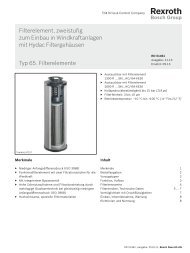
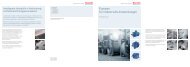
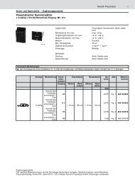
Clockwise rotation of the<br />
knob increases pressure<br />
unless otherwise specified.<br />
240 ° max. effective knob<br />
rotation. (Adjustable)<br />
OUTLINE DIMENSIONS<br />
Page 3
<strong>VALVE</strong><br />
FUNCTION<br />
Exhaust<br />
Inlet<br />
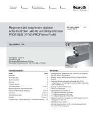
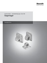
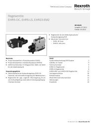
Description of Operation<br />
DESCRIPTION OF OPERATION<br />
Outlet<br />
When the knob is in released position, the “IN” port is<br />
closed to supply pressure and “OUT” port is open to<br />
exhaust.<br />
Note in the diagrammatic, when the knob is rotated to<br />
increase pressure, the shaft and cam are also rotated. The<br />
rotation of the knob allows the cam to push down the<br />
pressure control plunger, closing the lower exhaust valve<br />
and opening the upper supply valve which permits air flow<br />
to out port delivery and the upper diaphragm chamber. As<br />
the pressure builds up in the delivery line it acts through<br />
the sensing port orifice and deflects the control diaphragm<br />
downward, compressing the control spring. When sufficient<br />
diaphragm deflection is reached to allow the upper supply<br />
valve in the pressure control portion to close, the pressure<br />
in the delivery line is held to that valve. The valve of the<br />
pressure delivered to the outlet port is proportional to the<br />
pressure control plunger movement. This movement in turn<br />
is controlled by the cam contour and is therefore<br />
proportional to the knob travel.<br />
The Controlair Valve will automatically compensate for<br />
downstream air pressure changes in the graduated<br />
pressure delivery line. These air pressure changes can be<br />
caused by line leakage, temperature change or load<br />
feedback. If air pressure at the outlet port increases over<br />
that called for by handle position, the diaphragm in the<br />
control portion will deflect downward opening the lower<br />
exhaust valve and exhausting air until the original setting is<br />
obtained. If the pressure drops below that called for by the<br />
handle position, the decreased force on the diaphragm will<br />
allow the control spring to force the diaphragm upward,<br />
opening the upper supply valve to restore the set pressure.<br />
The range of pressure is controlled by the strength of the<br />
diaphragm spring. Various values are available as shown<br />
on Identity Schedule, page 5.<br />
The H-4 Controlair is factory set to provide normal 240<br />
degree rotation of the control knob. However, the 240degree<br />
rotation can be reduced by changing the<br />
relationship of the stop with the cam brake.<br />
Exhaust Valve<br />
Page 4<br />
Diaphragm<br />
Range Control<br />
Spring<br />
Exhaust Port<br />
DIAGRAMMATIC VIEW<br />
Inlet & Exhaust<br />
Valve Unit<br />
Supply Valve<br />
Adjusting Screw
New H-4<br />
Complete<br />
Part<br />
Number<br />
Old H-4<br />
Complete<br />
Part<br />
Number<br />
R431002818 P -050967<br />
-00001<br />
R431002819 P -050967<br />
-00002<br />
R431002820 P -050967<br />
-00003<br />
P -050967<br />
R431002821 -00004<br />
OBSOLETE<br />
P -050967<br />
-00006<br />
P -050967<br />
R431002822 -00008<br />
OBSOLETE<br />
OBSOLETE<br />
P -050967<br />
-00015<br />
P -050967<br />
-00016<br />
P -052742<br />
-00008<br />
P -051173<br />
R431002885 -00001<br />
P -051173<br />
R431002886 -00002<br />
P -051173<br />
R431002037 -00003<br />
Delivery<br />
Pressure<br />
IDENTITY SCHEDULE<br />
New Valve<br />
Portion<br />
Part<br />
Number<br />
Old Valve<br />
Portion<br />
Part<br />
Number<br />
0-65 psi R431002874 P -051133<br />
-00001<br />
0-100 psi R431002875 P -051133<br />
-00002<br />
0-125 psi R431002876 P -051133<br />
-00003<br />
0-150 psi R431002877 P -051133<br />
-00004<br />
New Control<br />
Spring<br />
Part<br />
Number<br />
Old Control<br />
Spring<br />
Part Number &<br />
Color Code<br />
R431003732 P -055442-00000<br />
Brown<br />
R431000043 -526749-0000<br />
Yellow<br />
R431000099 -540577-0000<br />
Lt. Blue<br />
R431003731 P -055441-00000<br />
Red<br />
0-20 psi OBSOLETE R431005473 P -060293-00000<br />
White<br />
0 -30 psi R431002878 P -051133<br />
-00008<br />
0-175 psi R431002879 P -051133<br />
-00015<br />
0-55 psi P -051133<br />
-00016<br />
0-30 psi P -057182<br />
-00008<br />
0-65 psi R431002874 P -051133<br />
-00001<br />
0-100 psi R431002875 P -051133<br />
-00002<br />
0-125 psi R431002876 P -051133<br />
-00003<br />
R431005475 P -060295-00000<br />
Dk. Blue<br />
R431003311 P -054159-0000<br />
Silver<br />
R431006501 P -064822-0000<br />
Plain<br />
R431005475 P -060295-0000<br />
Dk. Blue<br />
R431003732 P -055442-00000<br />
Brown<br />
R431000043 -526749-00000<br />
Yellow<br />
R431000099 -540577-00000<br />
Lt. Blue<br />
Remarks<br />
Clockwise knob rotation<br />
increases pressure<br />
Clockwise knob rotation<br />
increases pressure<br />
Clockwise knob rotation<br />
increases pressure<br />
Clockwise knob rotation<br />
Increases pressure<br />
Clockwise knob rotation<br />
Increases pressure<br />
Clockwise knob rotation<br />
Increases pressure<br />
Clockwise knob rotation<br />
increases pressure<br />
Clockwise knob rotation<br />
increases pressure<br />
Clockwise knob rotation<br />
increases pressure<br />
Counterclockwise knob<br />
pressure<br />
rotation increases<br />
Counterclockwise knob<br />
pressure<br />
increases pressure<br />
Counterclockwise knob<br />
pressure<br />
increases presssure<br />
* Control portion less pipe bracket with operator portion and mounting screws. (See pages 6 & 7 for item numbers and parts<br />
description).<br />
**Same as R431002822 (P -050967-00008) except diaphragm unit complete is R431003715 (P -055409-00002); items 10,<br />
13, 14 and 18 are part numbers R431000486 (P -005102-00000), R431003711 (P -055406-00000), R431001923 (P -<br />
049623-00113), and R431000489 (P -005103-00000) respectively (low temperature operation to -65°F or -54°C).<br />
Page 5
6<br />
20<br />
19<br />
2<br />
3<br />
21<br />
16<br />
14<br />
4<br />
1<br />
14<br />
15<br />
5<br />
9<br />
3<br />
7<br />
14<br />
12<br />
7<br />
13 (Note 3)<br />
8 (Note 3)<br />
10<br />
31<br />
31<br />
EXPLODED VIEW<br />
Note:<br />
1. See page 5 & 7 for part<br />
number<br />
2. See page 8 for repair kits<br />
3. Matched/lapped set of item<br />
13 & 8 are in kit, P/N<br />
R431003892<br />
(P -055687-00000), page 8<br />
See Identity Schedule<br />
Page 6<br />
26<br />
Valve Control Portion Complete<br />
(See Identity Schedule, Page 5)<br />
24<br />
23<br />
30<br />
33C<br />
33A<br />
33B<br />
25<br />
27<br />
29<br />
33B<br />
28<br />
32
PARTS LIST<br />
Ref. Qty Description New Part Number Old Part Number<br />
1 1 Adjusting screw R431006770 P -066209-00000<br />
2 1 Spring housing with nut R431006822 P -066488-00002<br />
3 4 Nuts, 5/16” – 18 R431002419 P -049901-00020<br />
4 1 Spring set R431000036 -526347-00000<br />
5 1 Control Spring (See identity schedule, Pg. 4) (See identity schedule, Pg. 4)<br />
6 1 Body with 2 studs R431000045 -526874-00000<br />
7 2 5/16” – 18 X 1 3/8” Cap screws R431000160 -850557-00000<br />
1 Diaphragm Unit incl. 8, 9, 10, 11, 12 * SEE KITS * SEE KITS<br />
8 1 Exhaust valve seat * SEE KITS * SEE KITS<br />
9 1 11/16” O.D. “O” ring * SEE KITS * SEE KITS<br />
10 1 Diaphragm * SEE KITS * SEE KITS<br />
11 1 Diaphragm follower * SEE KITS * SEE KITS<br />
12 1 5/16” – 18 Hex nut * SEE KITS * SEE KITS<br />
13 1 Inlet and exhaust valve * SEE KITS * SEE KITS<br />
14 2 ¾” O.D. “O” ring * SEE KITS * SEE KITS<br />
15 1 Exhaust valve spring * SEE KITS * SEE KITS<br />
16 1 Boot, dirt protector * SEE KITS * SEE KITS<br />
17 2 Strainers * SEE KITS * SEE KITS<br />
18 2 Gasket * SEE KITS * SEE KITS<br />
19 1 Pin, pivot R431001563 P -048189-00000<br />
20 2 Retaining ring, ¼ R431001844 P -049528-00001<br />
21 1 Cam dog R431003014 P -052835-00000<br />
22 1 ¼” – 20 X ¾” Screw R431002085 P -049728-00011<br />
23 1 Spring seat, washer R431002466 P -049904-00053<br />
24 1 Spring * SEE KITS * SEE KITS<br />
25 1 Shaft R431003713 -055407-00000<br />
26 1 Cam (clockwise) * SEE KITS * SEE KITS<br />
26a 1 Cam (counterclockwise) R431000095 -539406-00000<br />
27 2 1/8” X ½” Key R431002108 P -049767-00002<br />
28 1 Brake * SEE KITS * SEE KITS<br />
29 1 Adjustable stop * SEE KITS * SEE KITS<br />
30 1 ¼” – 20 X ½” Screw R431001873 P49592-0004<br />
31 2 3/8” – 16 X 1 ¾” Cap screws R431000161 -850563-00000<br />
32 1 Pipe bracket complete R431004173 P -057557-00000<br />
33 1 Knob assembly incl. 33a, 33b, 33c, R431006420 P -064421-00000<br />
33a 1 Knob, adjustment * SEE KITS * SEE KITS<br />
33b 2 Set screw, ¼ - 20 X ½ * SEE KITS * SEE KITS<br />
33c 1 Position plate * SEE KITS * SEE KITS<br />
NOTE: Parts List Items 1 through 21—Control Portion<br />
Parts List Items 22 through 33—Pipe Bracket With Operator Portion<br />
* Kits listed on page 8.<br />
Page 7
New Part<br />
Number<br />
R431003895<br />
R431004887<br />
R431006425<br />
R431006420<br />
Old Part Number<br />
REPAIR KITS<br />
Quantity<br />
Per<br />
Valve<br />
P -055687-K0000* 1<br />
P -059028-K0000 1<br />
Description<br />
Minor Graduating Valve Portion – repair kit (includes<br />
items 8,9,10,11,12,13, 14) see note<br />
Major Graduating Valve Portion – repair kit (includes<br />
items 15,16,17,18 and kit R431003892)<br />
P -064421-K0000 1 Knob Kit (includes items 33a, 33b,33c)<br />
P -064421-00006 1<br />
R431006421 P -064221-00007 1 Handle operator for H-4<br />
Notes:<br />
Operator Kit for clockwise*<br />
(includes items 24,26,28,29 and kit R431000132)<br />
1. *The inlet and exhaust valve unit item 13 and exhaust valve seat item 8 are lapped<br />
together to form a matched set. Kit contains these items factory matched.<br />
2. Select replacement range control spring from identity schedule page 5.<br />
3. All repair kits above include small tubes of recommended lubricant.<br />
4. Valve portion kits listed above contain seals and other parts that are recommended for<br />
repair of valve portion only.<br />
5. On severely worn or damaged components, additional parts my be required especially in<br />
the mechanical operating portions of the valve. Select as required from parts list on pages<br />
6 and 7.<br />
* For counterclockwise, order this kit plus cam part no. R431000095<br />
Page 8
Repair and Maintenance Instructions<br />
Repair and Maintenance Instructions<br />
When it has been determined that the Controlair®<br />
Valve requires repairs, the following general<br />
instructions are recommended.<br />
Disassembly, Cleaning and Lubrication<br />
Completely disassemble the Controlair valve. Wash<br />
all metal parts in a non-flammable solvent. Rinse<br />
each part thoroughly and blow dry with low<br />
pressure air.<br />
Inspect and clean the inlet filter Item #17 and both<br />
gaskets Item #18. Be sure all passages in the body<br />
and pipe bracket and sensing port orifice in top of<br />
the diaphragm chamber are clean and unrestricted.<br />
Examine all parts carefully. Replace all rubber parts<br />
and all worn or damaged parts. The use of repair<br />
kits is recommended.<br />
Reassemble<br />
Refer to exploded Parts and Assembly Views.<br />
Valves should always be reassembled using new<br />
rubber parts.<br />
Lubricate all metal to metal wear surfaces with<br />
Lubriplate 107 Grease. Lubricate all the rubber<br />
parts, except the diaphragm with Dow Corning<br />
No. 55 Pneumatic Grease.<br />
The exhaust valve and seat if not replaced should<br />
be polished for minimum leakage using a 600 grit<br />
lapping compound. Be sure to clean these parts<br />
prior to installing in the valve.<br />
Installing the knob (Item #33a), seat the knob on<br />
the shaft, Item #25 before installing the set screw,<br />
Item #33b.<br />
Do not over torque the set screw.<br />
Page 9<br />
Adjustments<br />
There is one adjustment that can be made to the H-<br />
4 Controlair Valves. This is the adjusting screw item<br />
#1, that varies the output pressure.<br />
Graduated Output Pressure Adjustments<br />
Adjusting screw Item #1 varies the maximum<br />
pressure setting. Turning the adjusting screw “in”<br />
raises the maximum pressure. Turning the screw<br />
“out” decreases the maximum pressure. The<br />
maximum control pressure adjustment should not<br />
exceed the maximum control pressure shown in the<br />
Identity Schedule for that part number. (Control<br />
Springs are color coded).<br />
The maximum output pressure rating can be<br />
changed by changing the control spring Item #5.<br />
With air supplied to the valve, move handle from<br />
start to full travel position. Adjust graduating valve<br />
screw Item #1 to obtain the maximum control<br />
pressure per Identity schedule. Move handle back<br />
to neutral position and note delivery line is<br />
exhausted to zero.<br />
Special Preload Setting<br />
This setting calls for a predetermined delivery<br />
pressure.
Testing and Test Set-Up (See Test Arrangement Diagram)<br />
Testing<br />
After any repair or adjustments, the H-4 Controlair®<br />
Valve should be tested using the following procedures<br />
and test arrangements described in this section.<br />
Pressure control valves need to be tested for the<br />
following:<br />
1. Function 4. Flow Capacity<br />
2. Pressure Range 5. Response<br />
3. Leakage 6. Mechanical Detents<br />
The adjustments affecting these points were described<br />
in the previous sections.<br />
General instructions for accomplishing these tests are<br />
listed below.<br />
1. Function: The H-4 Controlair Valves are rotary<br />
actuated 3-way pressure graduating valves.<br />
Rotating the knob actuates the valve to increase,<br />
decrease or maintain graduated air pressure to the<br />
“OUT” port or delivery line.<br />
2. Pressure Range: Supply pressure at “IN” port will<br />
be delivered as graduated pressure to the “OUT” or<br />
delivery port depending upon the range of the<br />
control spring being used and the handle position.<br />
The handle in the “OFF” or returned position the<br />
“OUT” or delivery port is at minimum pressure<br />
setting. Moving the handle actuates the graduating<br />
control portion to deliver graduated<br />
pressure to the “OUT” or delivery port. Check the<br />
valve to confirm the Minimum Pressure of 30 psi<br />
(2 Bar) and Maximum pressure of 70 psi (4.9<br />
Bar).<br />
3. Leakage: Set supply pressure to 20 psi (1.4 Bar)<br />
above maximum delivery pressure of the valve<br />
being tested. Using soap and water solution, coat<br />
the valve at the pipe bracket and spring housing<br />
parting lines. No leakage is permitted in any handle<br />
position.<br />
A. Port (IN)<br />
1. On all valves with spring ranges less than 90<br />
psi (6.2 bar), set supply line pressure to 100 psi<br />
(6.9 bar). Move handle to full travel position<br />
and hold (detent position on detented valves).<br />
Close valve in supply line to “IN” port or<br />
delivery line to isolate graduating valve.<br />
Observe delivery pressure gage in line. A<br />
pressure drop of no more than 2 psi (0.14 bar)<br />
in 30 seconds is permitted.<br />
4. Flow Capacity: Set supply line pressure to 100 psi<br />
(6.9 bar) regardless of the control spring rating.<br />
Moving the handle from “OFF” position to the full<br />
travel position, the delivery volumes should start to<br />
fill within the time limits shown in Table 1.<br />
Move the handle quickly from full travel position to<br />
back to “OFF” position. This should exhaust<br />
volumes within the time limits shown on table 1.<br />
Note: valves with less than 0 to 35 psi (2.4 bar) or<br />
less rated springs require an additional volume as<br />
shown in test arrangement diagram.<br />
5. Response: Rotate the knob to full travel position<br />
and hold. Fully open the valve at test volume so<br />
that that the air exhausts through the choke plug.<br />
Observe the delivery pressure gage at volume (1).<br />
A pressure drop of no more than 3 psi (0.2 Bar) is<br />
permitted.<br />
Page 10<br />
Valve<br />
Range<br />
0 to15<br />
psi<br />
0 to20<br />
psi<br />
0 to25<br />
psi<br />
0 to30<br />
psi<br />
0 to 35<br />
psi<br />
0 to 65<br />
psi<br />
0 to<br />
100 psi<br />
0 to<br />
125 psi<br />
0 to<br />
150 psi<br />
0 to 65<br />
psi<br />
35 to<br />
85 psi<br />
Flow Capacity Tests- Ports 1 & 3<br />
Fill Psi<br />
0 to 15<br />
psi<br />
0 to 15<br />
psi<br />
0 to 15<br />
psi<br />
0 to 15<br />
psi<br />
0 to 15<br />
psi<br />
0 to 50<br />
psi<br />
0 to 50<br />
psi<br />
0 to 50<br />
psi<br />
0 to 50<br />
psi<br />
0 to 15<br />
psi<br />
35 to<br />
70 psi<br />
Test Ranges & Times<br />
Max.<br />
Time-<br />
Sec<br />
2 sec<br />
2 sec<br />
2 sec<br />
2 sec<br />
2 sec<br />
2 sec.<br />
2 sec.<br />
2 sec.<br />
2 sec.<br />
2 sec.<br />
2 sec,<br />
Exhaust<br />
Psi<br />
15 to 5<br />
psi<br />
15 to 5<br />
psi<br />
15 to 5<br />
psi<br />
15 to 5<br />
psi<br />
15 to 5<br />
psi<br />
50 to 10<br />
psi<br />
50 to 10<br />
psi<br />
50 to 10<br />
psi<br />
50 to 10<br />
psi<br />
50 to 10<br />
psi<br />
70 to 40<br />
psi<br />
Max.<br />
Time<br />
2 sec.<br />
2 sec.<br />
2 sec.<br />
2 sec.<br />
2 sec.<br />
2 sec.<br />
2 sec.<br />
2 sec.<br />
2 sec.<br />
2 sec.<br />
2 sec.<br />
Test<br />
Vol.<br />
450<br />
cu.in.<br />
450<br />
cu.in.<br />
450<br />
cu.in.<br />
450<br />
cu.in.<br />
450<br />
cu.in.<br />
225<br />
cu. In.<br />
225<br />
cu. In.<br />
225<br />
cu. In.<br />
225<br />
cu. In.<br />
225<br />
cu. In.<br />
225<br />
cu. In.
Notes:<br />
1. Taskmaster Timing Volumes, part number R434002699 (TM-058887-00225), can be used for the<br />
volumes indicated.<br />
2. The supply air lines to the valves and delivery lines must be full size as shown. Line length must not<br />
exceed 3 feet (1 meter) between the supply valve and “IN” port, and between the “OUT” port and<br />
delivery test volumes. The piping connections must have zero leakage, and must not restrict the<br />
flow. If quick couplers are used, be sure they are full flow or oversize.<br />
3. It is recommended that as large a gage as practical be used on the delivery lines. A 6” gage is<br />
recommended.<br />
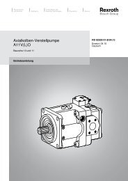
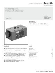
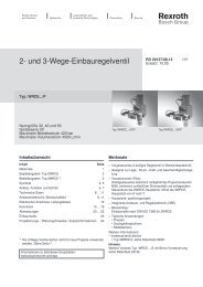
PRESSURE<br />
GAGE<br />
TO SUPPLY PORT<br />
IN<br />
REXROTH<br />
P/N (PD-020031-00191)<br />
OUT<br />
RECOMMENDED<br />
REXROTH P/N<br />
R432016357<br />
(PR-007816-00019)<br />
Test Arrangement Diagram<br />
DELIVERY<br />
PRESSURE GAGE<br />
TO DELIVERY PORT<br />
1/4” PIPE SCHEDULE 40<br />
OR<br />
3/4” O.D. TUBING<br />
OR<br />
#6 SINGLE BRAID HOSE<br />
Page 11<br />
TEST <strong>VALVE</strong><br />
225 in 3 225 in 3<br />
CHOCK PLUG .032<br />
OPTIONAL:<br />
REQUIRED FOR LOW SPRING<br />
RANGE <strong>VALVE</strong>S ON LY.<br />
CLEAN, DRY, CHEMICAL FREE AIR<br />
SUPPLY 200 PSI (14 Bar) MAXIMUM (OR 20<br />
PSI (1 Bar) ABOVE MAXIMUM DELIVERY<br />
PRESSURE OF ANY <strong>VALVE</strong> TESTED).
NOTICE TO PRODUCT USERS<br />
1. WARNING: FLUID MEDIA<br />
<strong>Bosch</strong> <strong>Rexroth</strong> pneumatic devices are designed and tested for use with<br />
filtered, clean, dry, chemical free air at pressures and temperatures within<br />
the specified limits of the device. For use with media other than air or for<br />
human life support systems, <strong>Bosch</strong> <strong>Rexroth</strong> must be consulted. Hydraulic<br />
cylinders are designed for operation with filtered, clean, petroleum based<br />
hydraulic fluid; operation using fire-resistant or other special types of fluids<br />
may require special packing and seals. Consult the factory.<br />
2. WARNING: MATERIAL COMPATIBILITY<br />
Damage to product seals or other parts caused by the use of<br />
noncompatible lubricants, oil additives or synthetic lubricants in the air<br />
system compressor or line lubrication devices voids <strong>Bosch</strong> <strong>Rexroth</strong>'s<br />
warranty and can result in product failure or other malfunction. See<br />
lubrication recommendations below.<br />
AIR LINE LUBRICANTS! In service higher than 18 cycles per minute or<br />
with continuous flow of air through the device, an air line lubricator is<br />
recommended.* (Do not use line lubrication with vacuum products.)<br />
However, the lubricator must be maintained since the oil will wash out the<br />
grease, and lack of lubrication will greatly shorten the life expectancy. The<br />
oils used in the lubricator must be compatible with the elastomers in the<br />
device. The elastomers are normally BUNA-N, NEOPRENE, VITON,<br />
SILICONE and HYTREL. <strong>Bosch</strong> <strong>Rexroth</strong> recommends the use of only<br />
petroleum based oils without synthetic additives, and with an aniline point<br />
between 180° F and 210° F.<br />
COMPRESSOR LUBRICANTS! All compressors (with the exception of<br />
special "oil free" units) pass oil mist or vapor from the internal crankcase<br />
lubricating system through to the compressed air. Since even small<br />
amounts of non-compatible lubricants can cause severe seal deterioration<br />
(which could result in component and system failure) special care should<br />
be taken in selecting compatible compressor lubricants. It is<br />
recommended that users review the National Fluid Power Association<br />
"Recommended Guide Lines For Use Of Synthetic Lubricants In<br />
Pneumatic Fluid Power Systems" (NFPA T1.9.2-1978).<br />
3. WARNING: INSTALLATION AND MOUNTING<br />
The user of these devices must conform to all applicable electrical,<br />
mechanical, piping and other codes in the installation, operation or repair<br />
of these devices.<br />
INSTALLATION ! Do not attempt to install, operate or repair these<br />
--Refer to the appropriate service catalog for parts and service information.<br />
Page 12<br />
devices without proper training in the technique of working on pneumatic<br />
or hydraulic systems and devices, unless under trained supervision.<br />
Compressed air and hydraulic systems contain high levels of stored<br />
energy. Do not attempt to connect, disconnect or repair these products<br />
when a system is under pressure. Always exhaust or drain the pressure<br />
from a system before performing any service work. Failure to do so can<br />
result in serious personal injury.<br />
MOUNTING! Devices should be mounted and positioned in such a<br />
manner that they cannot be accidentally operated.<br />
4. WARNING: APPLICATION AND USE OF PRODUCTS<br />
The possibility does exist for any device or accessory to fail to operate<br />
properly through misuse, wear or malfunction. The user must consider<br />
these possibilities and should provide appropriate safe guards in the<br />
application or system design to prevent personal injury or property<br />
damage in the event of a malfunction.<br />
5. WARNING: CONVERSION, MAINTENANCE AND REPAIR<br />
When a device is disassembled for conversion to a different configuration,<br />
maintenance or repair, the device must be tested for leakage and proper<br />
operation after being reassembled and prior to installation.<br />
MAINTENANCE AND REPAIR! Maintenance periods should be<br />
scheduled in accordance with frequency of use and working conditions. All<br />
<strong>Bosch</strong> <strong>Rexroth</strong> products should provide a minimum of 1,000,000 cycles of<br />
maintenance free service when used and lubricated as recommended.<br />
However, these products should be visually inspected for defects and<br />
given an "in system" operating performance and leakage test once a year.<br />
Where devices require a major repair as a result of the one million cycles,<br />
one year, or routine inspection, the device must be disassembled,<br />
cleaned, inspected, parts replaced as required, rebuilt and tested for<br />
leakage and proper operation prior to installation. See individual catalogs<br />
for specific cycle life estimates.<br />
6. PRODUCT CHANGES<br />
Product changes including specifications, features, designs and<br />
availability are subject to change at any time without notice. For critical<br />
dimensions or specifications, contact factory.<br />
*Many <strong>Bosch</strong> <strong>Rexroth</strong> pneumatic valves and cylinders can operate with or<br />
without air line lubrication; see individual sales catalogs for details.<br />
LIMITATIONS OF WARRANTIES & REMEDIES<br />
<strong>Bosch</strong> <strong>Rexroth</strong> warrants its products sold by it to be free from defects in material and workmanship to the following:<br />
For twelve months after shipment <strong>Bosch</strong> <strong>Rexroth</strong> will repair or replace (F.O.B. our works), at its option, any equipment which under normal conditions<br />
of use and service proves to be defective in material or workmanship at no charge to the purchaser. No charge will be made for labor with respect<br />
to defects covered by this Warranty, provided that the work is done by <strong>Bosch</strong> <strong>Rexroth</strong> or any of its authorized service facilities. However, this<br />
Warranty does not cover expenses incurred in the removal and reinstallation of any product, nor any downtime incurred, whether or not proved<br />
defective.<br />
All repairs and replacement parts provided under this Warranty policy will assume the identity, for warranty purposes, of the part replaced, and the<br />
warranty on such replacement parts will expire when the warranty on the original part would have expired. Claims must be submitted within thirty<br />
days of the failure or be subject to rejection.<br />
This Warranty is not transferable beyond the first using purchaser. Specifically, excluded from this Warranty are failures caused by misuse, neglect,<br />
abuse, improper operation or filtration, extreme temperatures, or unauthorized service or parts. This Warranty also excludes the use of lubricants,<br />
fluids or air line additives that are not compatible with seals or diaphragms used in the products. This Warranty sets out the purchaser's exclusive<br />
remedies with respect to products covered by it, whether for negligence or otherwise. Neither <strong>Bosch</strong> <strong>Rexroth</strong> nor any of its affiliates will be liable<br />
for consequential or incidental damages or other losses or expenses incurred by reason of the use or sale of such products. Our liability (except<br />
as to title) arising out of the sale, use or operation of any product or parts, whether on warranty, contract or negligence (including claims for<br />
consequential or incidental damage) shall not in any event exceed the cost of replacing the defective products and, upon expiration of the<br />
warranted period as herein provided, all such liability is terminated. THIS WARRANTY IS IN LIEU OF ALL OTHER WARRANTIES, EXPRESS OR<br />
IMPLIED, WHETHER FOR MERCHANTABILITY OR FITNESS FOR A PARTICULAR PURPOSE OR OTHERWISE. No attempt to alter, amend or<br />
extend this Warranty shall be effective unless authorized in writing by an officer of <strong>Bosch</strong> <strong>Rexroth</strong> Division.<br />
<strong>Bosch</strong> <strong>Rexroth</strong> reserves the right to discontinue manufacture of any product, or change product materials, design or specifications without notice.<br />
This is a Year 2000 Readiness disclosure as defined and used in the Year 2000 Information and Readiness Disclosure Act:<br />
Notwithstanding any provision to the contrary, Seller acknowledges the potential Year 2000 problem and hereby promises to use its good faith, best<br />
efforts to attempt to be Year 2000 Compliant as soon as practicable. "Year 2000 Compliant" means that Seller's goods and services will be<br />
designed to be used prior to, during, and after calendar year 2000 A.D., and to operate during each such time period without substantive error<br />
relating to date data, specifically including any substantive error relating to, or the product of, date data which represents or references different<br />
centuries or more than one century, and will recognize the calendar year 2000 A.D. as a leap year.
International offices:<br />
Asia:<br />
China Russia<br />
India Singapore<br />
Japan South Korea<br />
Malaysia<br />
Australia<br />
Europe:<br />
Austria Netherlands<br />
Belgium Norway<br />
Bulgaria Poland<br />
Czech Republic Portugal<br />
Denmark Romania<br />
Finland Slovakia<br />
France Spain<br />
Germany Sweden<br />
Greece Switzerland<br />
Hungary Turkey<br />
Italy Ukraine<br />
United Kingdom<br />
North America:<br />
Canada United States<br />
Mexico<br />
South America:<br />
Argentina Venezuela<br />
Brazil<br />
©2008 <strong>Bosch</strong> <strong>Rexroth</strong> Corporation<br />
Factory Automation<br />
Regional sales offices:<br />
Central<br />
<strong>Bosch</strong> <strong>Rexroth</strong> Corporation<br />
5150 Prairie Stone Parkway<br />
Hoffman Estates, IL 60192-3707<br />
Telephone (847) 645-3600<br />
Facsimile (847) 645-0804<br />
Great Lakes<br />
<strong>Bosch</strong> <strong>Rexroth</strong> Corporation<br />
2730 Research Drive<br />
Rochester Hills, MI 48309<br />
Telephone (248) 393-3330<br />
Facsimile (248) 393-2893<br />
Northeast<br />
<strong>Bosch</strong> <strong>Rexroth</strong> Corporation<br />
99 Rainbow Road<br />
East Granby, CT 06026-0000<br />
Telephone (860) 844-8377<br />
Facsimile (860) 844-8595<br />
<strong>Bosch</strong> <strong>Rexroth</strong> Corporation<br />
2315 City Line Road<br />
Bethlehem, PA 18017-2131<br />
Telephone (610) 694-8300<br />
Facsimile (610) 694-8467<br />
Southeast<br />
<strong>Bosch</strong> <strong>Rexroth</strong> Corporation<br />
14001 South Lake Drive<br />
Charlotte, NC 28273-5544<br />
Telephone (704) 583-4338<br />
Facsimile (704) 583-0523<br />
West<br />
<strong>Bosch</strong> <strong>Rexroth</strong> Corporation<br />
11 Goddard<br />
Irvine, CA 92618-4600<br />
Telephone (949) 450-2777<br />
Facsimile (949) 450-2790<br />
North American offices:<br />
<strong>Bosch</strong> <strong>Rexroth</strong> Corporation<br />
Corporate Headquarters<br />
5150 Prairie Stone Parkway<br />
Hoffman Estates, IL 60192-3707<br />
Telephone (847) 645-3600<br />
Facsimile (847) 645-0804<br />
<strong>Bosch</strong> <strong>Rexroth</strong> Corporation<br />
Industrial Hydraulics<br />
2315 City Line Road<br />
Bethlehem, PA 18017-2131<br />
Telephone (610) 694-8300<br />
Facsimile (610) 694-8467<br />
<strong>Bosch</strong> <strong>Rexroth</strong> Corporation<br />
Electric Drives and Controls<br />
5150 Prairie Stone Parkway<br />
Hoffman Estates, IL 60192-3707<br />
Telephone (847) 645-3600<br />
Facsimile (847) 645-6201<br />
<strong>Bosch</strong> <strong>Rexroth</strong> Corporation<br />
Linear Motion and Assembly<br />
Technologies<br />
816 E. Third Street<br />
Buchanan, MI 49107<br />
Telephone (269) 695-0151<br />
Facsimile (269) 695-5363<br />
14001 South Lakes Drive<br />
Charlotte, NC 28273<br />
Telephone (800) 438-5983<br />
Facsimile (704) 583-0523<br />
<strong>Bosch</strong> <strong>Rexroth</strong> Corporation<br />
Mobile Hydraulics<br />
145 Southchase Boulevard<br />
Fountain Inn, SC 29644-9018<br />
Telephone (864)967-2777<br />
Facsimile (864)962-5338<br />
<strong>Bosch</strong> <strong>Rexroth</strong> Corporation<br />
Pneumatics<br />
1953 Mercer Road<br />
Lexington, KY 40511-1021<br />
Telephone (859) 254-8031<br />
Facsimile (859) 254-4188<br />
pneumatics@boschrexroth-us.com<br />
www.boschrexroth-us.com /brp<br />
<strong>Bosch</strong> <strong>Rexroth</strong> Canada<br />
3426 Mainway Drive<br />
Burlington, Ontario L7M 1A8 Telephone<br />
(905) 335-5511 Facsimile (905) 335-4184<br />
www.boschrexroth.ca<br />
<strong>Bosch</strong> <strong>Rexroth</strong>, S.A. de C.V.<br />
Calle Neptuno # 72<br />
Unidad Industrial Vallejo<br />
CP 07700 Mexico, D.F.<br />
Telephone (555) 754-1711<br />
Facsimile (555) 752-5943<br />
Further contacts:<br />
www.boschrexroth.com/addresses<br />
The data specified herein only<br />
serves to describe the product. No<br />
statements concerning a certain<br />
condition or suitability for a certain<br />
application can be derived from our<br />
information. The given information<br />
does not release the user from<br />
obligation of own judgment and<br />
verification. It must be remem-<br />
bered that our products are sub-<br />
ject to a natural process of wear<br />
and aging. ©This document, as<br />
well as the data, specifications and<br />
other information set forth in it, are<br />
the exclusive property of <strong>Bosch</strong><br />
<strong>Rexroth</strong> Corp. Without their con-<br />
sent it may not be reproduced or<br />
given to third parties.<br />
Printed in the United States<br />
SM-800.6516<br />
(Supercedes B4-65.16)<br />
November 2008