Pascal Delapierre's Article on Keels
Pascal Delapierre's Article on Keels
Pascal Delapierre's Article on Keels

You also want an ePaper? Increase the reach of your titles
YUMPU automatically turns print PDFs into web optimized ePapers that Google loves.
Keel proporti<strong>on</strong>s<br />
(translati<strong>on</strong> and completi<strong>on</strong> of article Fra-19, available in French and Spanish)<br />
The Argentine fleet are certainly the largest RG65 fleet, arguably <strong>on</strong>e where competiti<strong>on</strong><br />
would have let evoluti<strong>on</strong> laws rule, and I was very surprised to see how little draught they had.<br />
I therefore attempted a set of calculati<strong>on</strong>s to review this against theory.<br />
After a few attempts, I eventually c<strong>on</strong>cluded that a sensible criteri<strong>on</strong> for the analysis was the<br />
submerged fr<strong>on</strong>t surface of the model, i.e. taking into account its hull, keel and ballast. This<br />
assumes that the drag coefficient of all three elements is “comparable”, will come back to this<br />
in c<strong>on</strong>clusi<strong>on</strong>.<br />
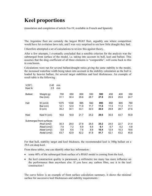
Calculati<strong>on</strong>s were run for several ballast/draught ratios giving the same stability to the model,<br />
the increased waterline width being taken into account in the stability calculati<strong>on</strong> as the hull is<br />
loaded by heavier ballast, for several target stabilities and keel thicknesses. An example of<br />
result table is the following :<br />
V(30°) 2.40 m/s<br />
Keel tk 3.5 mm<br />
Ballast Weight (g) 700 650 600 550 500 450 400 350<br />
Dia (mm) 31.1 30.4 29.6 28.7 27.8 26.9 25.8 24.7<br />
Hull W (cm3) 1075 1030 985 940 895 850 805 760<br />
Bwl (cm) 12.1 12.0 11.9 11.7 11.6 11.5 11.3 11.1<br />
D (cm) 35.2 34.1 33.1 32.0 30.9 29.8 28.7 27.6<br />
Keel Keel H (cm) 16.6 18.9 21.7 25.2 29.6 35.5 43.7 55.9<br />
Submerged fr<strong>on</strong>t surfaces<br />
Ahull (cm2) 30.3 29.0 27.8 26.5 25.2 24.0 22.7 21.4<br />
Alead (cm2) 7.6 7.2 6.9 6.5 6.1 5.7 5.2 4.8<br />
Akeel (cm2) 5.8 6.6 7.6 8.8 10.4 12.4 15.3 19.6<br />
Atotal (cm2) 43.7 42.9 42.2 41.8 41.7 42.1 43.2 45.8<br />
For that hull, stability target and keel thickness, the recommended keel is 500g ballast <strong>on</strong> a<br />
29.6 cm deep keel.<br />
From these tables, <strong>on</strong>e can identify other key informati<strong>on</strong> :<br />
• some 40% of the submerged fr<strong>on</strong>t surface of a RG65 model is coming from the keel,<br />
• the keel c<strong>on</strong>structi<strong>on</strong> quality is paramount, a millimetre too many has more influence <strong>on</strong><br />
the performance than anywhere else. If you have any carb<strong>on</strong> fibre, use it in the keel<br />
c<strong>on</strong>structi<strong>on</strong> !<br />
The curve below is an example of fr<strong>on</strong>t surface calculati<strong>on</strong> summary, it shows the minimal<br />
surface for successive keel thicknesses and stability requirements :
This family of curves is based <strong>on</strong> stability formulae published within article<br />
http://navi.modelisme.com/article135.html, completed to calculate the submerged fr<strong>on</strong>t<br />
surfaces. Such diagram was produced for successive keel thicknesses.<br />
The ballast weight / keel depth pairs providing minimal fr<strong>on</strong>t surface for a given stability was<br />
finally presented in a single diagram, with keel thickness as additi<strong>on</strong>al parameter:<br />
The blue lines are the iso-stability curves.
The calculati<strong>on</strong>s were made <strong>on</strong> three hull forms, 11, 12 and 14cm wide. The optimal pairs<br />
proved almost independent from the hull, the keel can therefore be selected before the hull…<br />
These calculated optimal pairs propose deeper keels than certain Argentine <strong>on</strong>es, but the study<br />
clearly shows that draught cannot be increased forever. Finally, short keels still need to<br />
provide side surface, they become thicker when their chord increase …<br />
How much stability do you need ?<br />
The above calculati<strong>on</strong>s also show the cost for stability. The results using Colombine as<br />
example :<br />
Stability (V30)<br />
Fr<strong>on</strong>tal surface<br />
(3.25mm keel)<br />
Corresp<strong>on</strong>ding lead weight<br />
and keel depth<br />
2.3 m/s 39.0 cm2 475 g – 26.5 cm<br />
2.5 m/s 41.7 cm2 550 g – 27.5 cm<br />
2.7 m/s 44.4 cm2 600 g – 30.5 cm<br />
Here again, several schools of thought co-exist ; In Brazil, ballast weights of 650g or more are<br />
comm<strong>on</strong>, in Argentine, the models seem less and less stable (ref. JIF2).<br />
I currently plan to design against a 3.25mm keel thickness, and adopted :<br />
• a 500g ballast with a keel height of 27cm, and<br />
• a 650g ballast with a keel height of 33cm.<br />
Three rigs and two keels, we have six gears to our model. An example of gearbox balance:
C<strong>on</strong>structi<strong>on</strong><br />
If you have carb<strong>on</strong> fibre, I<br />
recommend using it all for the<br />
keel; it is not essential for the<br />
hull.<br />
I build my keel fins from a<br />
1.5mm wood core, <strong>on</strong> which I<br />
resin two layers of carb<strong>on</strong> and<br />
fibreglass <strong>on</strong> each side. The<br />
wood core is cut 1cm narrower<br />
than the final keel chord to<br />
allow the two fibre skins to<br />
join at the edges.<br />
The whole set is pressed<br />
together while curing.<br />
The 500g selecti<strong>on</strong> is<br />
especially sexy, as it doe not<br />
require to turn into a<br />
alchemist to get <strong>on</strong>e : it is<br />
available from stock in many<br />
fishing shops as “macquerel<br />
lead”. A few hammer fairing<br />
bangs, putty and you are there<br />
I perform attachment o the keel via a steel wire<br />
« staple » :A<br />
1. Hammer down a 5 to 8mm groove with a<br />
screwdriver head in the middle of the bulb.<br />
2. Make a “U” shape in a steel wire and clue it with<br />
epoxy into the groove, the two ends should<br />
protrude 1cm minimum and be parallel.<br />
3. Present the two ends to the keel wing and mark<br />
the positi<strong>on</strong>s to be drilled<br />
4. Glue the two steel wire ends into the keel wing<br />
with epoxy.<br />
The final product is meant to look like this…
C<strong>on</strong>clusi<strong>on</strong><br />
The assumpti<strong>on</strong> that all three forms, hull, ballast and keel have the same drag coefficient is<br />
certainly false, but I failed to find sensible literature <strong>on</strong> the subject. Remember that we sail in<br />
the laminar phase for the keel, and transiti<strong>on</strong> z<strong>on</strong>e for the hull, it’s all black art… Should you<br />
have reas<strong>on</strong>s to believe that the keel is x% more drag for the same fr<strong>on</strong>tal surface than the rest,<br />
you just need to multiply the keel thickness by the same x% before using the curves.