Elbow Plating System Brochure and Surgical Technique
Elbow Plating System Brochure and Surgical Technique
Elbow Plating System Brochure and Surgical Technique

You also want an ePaper? Increase the reach of your titles
YUMPU automatically turns print PDFs into web optimized ePapers that Google loves.
<strong>Elbow</strong> <strong>Plating</strong> <strong>System</strong>
2<br />
<strong>Elbow</strong> <strong>Plating</strong> <strong>System</strong><br />
Acumed is a global leader of innovative orthopaedic <strong>and</strong><br />
medical solutions.<br />
We are dedicated to pioneering products, service methods<br />
<strong>and</strong> approaches that improve patient care.<br />
CONTENTS<br />
Introducing the <strong>System</strong> 2<br />
<strong>Elbow</strong> <strong>Plating</strong> <strong>System</strong> Features 3<br />
Olecranon Plate Features 4<br />
Coronoid Plate Features 4<br />
Distal Humerus Plate Features 5<br />
Parallel Plate Placement 6<br />
Biomechanics 6<br />
Precontoured Plates 8<br />
Instrumentation 8<br />
Hexalobe Screw <strong>System</strong> 9<br />
Tap-Loc® Technology 10<br />
<strong>Surgical</strong> <strong>Technique</strong>s<br />
Olecranon Plate <strong>Surgical</strong> <strong>Technique</strong> 12<br />
Olecranon Osteotomy Cutting Jig <strong>Surgical</strong> <strong>Technique</strong> 14<br />
Distal Humerus Plate <strong>Surgical</strong> <strong>Technique</strong> 15<br />
Coronoid Plate <strong>Surgical</strong> <strong>Technique</strong> 18<br />
Ordering Information 20<br />
Notes 23<br />
Orthopaedic surgeons are continually developing improved methods of fracture<br />
fixation <strong>and</strong> rehabilitation. Acumed® recognizes that often these new fixation<br />
methods require changes <strong>and</strong> advancements in orthopaedic implants <strong>and</strong><br />
technology. Our goal is to design implants <strong>and</strong> instrumentation that address<br />
new fixation techniques, solve issues with current fixation methods <strong>and</strong> provide<br />
the best possible outcome for the patient.<br />
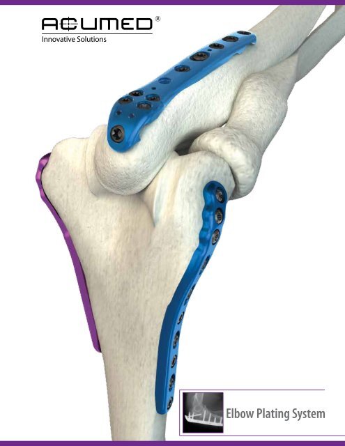
Designed to address fractures of the distal humerus, olecranon <strong>and</strong> coronoid,<br />
the <strong>Elbow</strong> <strong>Plating</strong> <strong>System</strong> offers precontoured, indication specific plates. The<br />
system features an innovative low-profile Olecranon Plate design with increased<br />
anatomic features <strong>and</strong> instrumentation to ease plate <strong>and</strong> screw insertion. The<br />
system features the Hexalobe Screw <strong>System</strong> with variable angle Tap-Loc®<br />
Technology for the Distal Humerus Plates.<br />
The <strong>Elbow</strong> <strong>Plating</strong> <strong>System</strong>, designed in conjunction with Shawn W. O’Driscoll,<br />
Ph.D., M.D., has revolutionized the way orthopaedic surgeons treat <strong>and</strong> manage<br />
elbow fractures since its market release in 2001. Dr. O’Driscoll’s experience has<br />
shown that the “parallel” plate placement on the distal humerus, combined with<br />
increased plate strength over st<strong>and</strong>ard reconstruction plates 1 , allows for early<br />
rehabilitation <strong>and</strong> preservation of elbow function <strong>and</strong> motion.
Precontoured Plate design eliminates the need for surgeons to bend the<br />
plates to match the anatomy of the patient. For complex fractures, the plates<br />
act as a template to restore the natural anatomic geometry of the distal<br />
humerus <strong>and</strong> proximal ulna.<br />
Parallel Plate Placement provides a more stable construct than plates<br />
placed at a 90° orientation 2 . Biomechanical data shows that parallel plate<br />
placement has greater strength <strong>and</strong> stability, especially when the elbow is<br />
subjected to A/P <strong>and</strong> torsional forces 3 .<br />
Hexalobe Screw <strong>System</strong> was designed specifically for fractures of<br />
the elbow. Variable Angle Tap-Loc® Technology allows up to 20° screw<br />
angulation, providing flexibility when capturing fracture fragments while<br />
maintaining the benefits of a traditional locking screw.<br />
Coronoid<br />
Olecranon<br />
Medial Column<br />
<strong>Elbow</strong> <strong>Plating</strong> <strong>System</strong> Features<br />
Lateral Column<br />
20°<br />
3
4<br />
Locking Olecranon Plates<br />
Technical Objectives for Locking Olecranon Plates:<br />
1. Each screw should be as long as possible.<br />
2. Locking screws should interlock to provide a stable<br />
“fixed angle” structure inside the bone fragment.<br />
3. Plate should buttress against anterior pull of elbow<br />
flexors.<br />
4. Plate should provide stable fixation of the ulnar shaft.<br />
5. Plate should be applied with compression across the<br />
fracture.<br />
6. Plate must be strong <strong>and</strong> stiff enough to resist bending<br />
before union occurs.<br />
Coronoid Plates<br />
The Locking Olecranon Plates provide excellent fixation in the proximal ulna<br />
for both fractures <strong>and</strong> osteotomies. The plates feature an advanced anatomic<br />
design with contours proximally <strong>and</strong> along the shaft to provide a precise<br />
anatomic fit as well as a lower profile than previous generation plates.<br />
Left <strong>and</strong> Right-specific plates greatly improve anatomic fit proximally <strong>and</strong><br />
distally along the ulnar shaft. An improved locking screw trajectory allows<br />
screws to capture fracture fragments without interference with other locking<br />
screws. Increased plate length range makes this Olecranon Plate <strong>System</strong> the<br />
most comprehensive plate offering on the market.<br />
Prongs on the proximal tip of the St<strong>and</strong>ard Plates provide provisional fixation<br />
into the triceps tendon, assisting with reduction <strong>and</strong> improving final stability.<br />
The plate is placed directly over the triceps tendon, eliminating the need for<br />
a triceps split. A 3-hole plate is included for osteotomies <strong>and</strong> more proximal<br />
olecranon fractures that do not require a longer plate length. A radiolucent<br />
targeting guide for the proximal 2.7mm screw cluster eases the surgical<br />
technique <strong>and</strong> may help to save valuable operating room time. K-wire holes<br />
facilitate provisional plate fixation.<br />
The Extended Plate family does not have prongs <strong>and</strong> is offered for the<br />
treatment of fractures that extend proximally. The proximal three holes are<br />
threaded to allow locking screws to be utilized. With the Extended Plates, the<br />
surgeon may choose several proximal locking screw options depending on<br />
the fixation needed for the particular fracture pattern. An angled “home run”<br />
screw in hole #3 or a long intramedullary screw in hole #2 may be utilized<br />
along with smaller fragment screws in the other proximal holes.<br />
Optional Narrow Plates were designed specifically for smaller patients under<br />
120lbs (54 kg) to fit smaller bone geometry. An optional 15-hole plate is<br />
available for the treatment of segmental fractures or where comminution<br />
extends distally along the ulnar shaft.<br />
Olecranon Plate lengths range from 65mm to 190mm.<br />
The Coronoid Plates are designed specifically for fractures of the anteromedial<br />
facet of the coronoid. The plate acts as a buttress to the coronoid <strong>and</strong><br />
counteracts the tendency of the elbow to subluxate. Threaded .035” <strong>and</strong><br />
.045” titanium wires are included for supplementary fixation of the small<br />
coronoid fragments if necessary.
Distal Humerus Plates<br />
Precontoured in three planes, the Locking Distal Humerus Plates offer<br />
multiple lengths <strong>and</strong> sizes to treat a wide variety of fractures.<br />
Lateral Column Plates<br />
These plates improve upon posterior plating biomechanically by enabling the<br />
use of longer screws that interdigitate with screws coming from the medial<br />
side. The Lateral Plates are offered in both Left (blue) <strong>and</strong> Right (green) <strong>and</strong><br />
are 11mm in width <strong>and</strong> 2.0mm at the thickest point. Lengths range from<br />
58mm to 206mm.<br />
Medial Column Plates<br />
Distally these plates extend down to, or wrap around the medial epicondyle<br />
or even extend down onto the medial trochlea. Extending up the condylar<br />
ridge, these locking plates offer solid fixation <strong>and</strong> compression. This fixation<br />
is maximized when the screws in the articular fragments can interdigitate<br />
with those coming from the lateral side. The Medial Plates are 11mm wide<br />
<strong>and</strong> 2.0mm at the thickest point <strong>and</strong> offer 2-4 screw holes for fixation of the<br />
articular fragments. Lengths range from 84mm to 175mm.<br />
Technical Objectives for Locking Distal Humerus Plates:<br />
1. Every screw should pass through a plate.<br />
2. Each screw engages a fragment on the opposite side that is<br />
also attached to a plate.<br />
3. Each screw should be as long as possible.<br />
4. Each screw should engage as many fragments as possible.<br />
5. The screws in the distal fragments should lock together by<br />
interdigitation, creating a “fixed angle” structure.<br />
6. Plates should be applied such that compression is achieved at<br />
the supracondylar level for both columns.<br />
7. Plates must be strong <strong>and</strong> stiff enough to resist breaking or<br />
bending before union occurs.<br />
Distal Humerus Plates<br />
5
6<br />
Parallel Plate Placement<br />
Biomechanical Testing<br />
Parallel <strong>Plating</strong><br />
Perpendicular <strong>Plating</strong><br />
The parallel placement of the Locking Distal Humerus Plates provides a<br />
strong, stable construct which may reduce the need for immobilization<br />
of the elbow for an extended postoperative period. The strength of the<br />
plates, along with the parallel application <strong>and</strong> locking technology, greatly<br />
reduces the chance of hardware failure. The patient may be able to begin<br />
rehabilitation <strong>and</strong> range of motion exercises immediately after surgery.<br />
Because screws come from opposing sides of the condyles, long screws are<br />
able to interdigitate in the distal fragments, creating an “arch” construct. The<br />
interdigitating screws provide the keystone to the arch, creating a stable<br />
construct to facilitate with immediate, aggressive rehabilitation.<br />
90° plate orientation was supported early on in a study that compared 90°<br />
plating to a Y-plate <strong>and</strong> crossed screws, but did not compare “perpendicular”<br />
to “parallel” plating 4 . A second comprehensive study found “parallel” plating<br />
to be the best construct for reconstruction of a comminuted distal humerus 5 .<br />
This study proved that plates placed in parallel configuration on the medial<br />
<strong>and</strong> lateral columns were stronger than 90° plating when a gap was present<br />
between the articular fragments <strong>and</strong> the shaft, as when the humerus is<br />
severely fractured. Both studies were written before the introduction of the<br />
<strong>Elbow</strong> <strong>Plating</strong> <strong>System</strong> which optimizes the biomechanics even further with<br />
locking capability, plate placement <strong>and</strong> plate strength.<br />
Finite element analysis testing at Acumed® indicated significant advantages<br />
of parallel plating versus 90° plating 6 . For this study, a computer modeled a<br />
distal humerus fracture <strong>and</strong> assumed equivalent plate fixation <strong>and</strong> strength<br />
(two areas in which the Acumed® Locking <strong>Elbow</strong> Plates are significantly<br />
better than 90° plating with reconstruction or tubular plates). The program<br />
simulated a load of 50lbs in three different planes: A/P, M/L, <strong>and</strong> Torsion. The<br />
results supported parallel plating, especially in torsional loads.<br />
90° <strong>Plating</strong> Displaced:<br />
Anterior/Posterior: 53% more<br />
Medial/Lateral: 5% less<br />
Torsion: 80% more
Results of a biomechanical study tested perpendicular 3.5mm LCP Distal<br />
Humerus Plates (316L) versus parallel Locking Distal Humerus Plates<br />
(titanium) for stiffness in compression <strong>and</strong> internal/external rotation, plastic<br />
deformation <strong>and</strong> failure in torsion 7 . Both systems were utilized for fixation of<br />
a distal intra-articular humerus fracture with a metaphyseal comminution<br />
in osteoporotic bone. Results showed that the Acumed® “parallel locking<br />
system showed improved stability compared with the perpendicular locking<br />
system, <strong>and</strong> therefore may be more indicated.”<br />
Locking Distal Humerus Plates provided a significantly higher stability in<br />
compression <strong>and</strong> external rotation, <strong>and</strong> a greater ability to resist axial plastic<br />
deformation.<br />
- Axial compressive stiffness of our plates was 2.3 times GREATER than the<br />
perpendicular locking system.<br />
- The perpendicular locking plates experienced an average of 2.9 times<br />
GREATER axial plastic deformation than the Acumed® plates.<br />
The Acumed® Locking Olecranon Plates are Grade 4 unalloyed titanium. Our<br />
previous generation Olecranon Plates are Grade 2 unalloyed titanium. Because<br />
Grade 4 unalloyed titanium has higher yield strength, the plates are able to be<br />
lower profile than our previous generation of plates without compromising<br />
strength.<br />
Mechanical testing of our Locking Olecranon Plates versus previous generation<br />
Olecranon Plates was performed utilizing two separate loading scenarios<br />
for metaphyseal <strong>and</strong> diaphyseal plate strength. Both scenarios investigated<br />
direct load to failure of the plate. Failure of the plate was considered to have<br />
occurred when permanent plastic deformation of the plate occurred.<br />
The Acumed® Grade 4 unalloyed titanium Olecranon Plates have a 6%<br />
lower profile than our Grade 2 unalloyed titanium Olecranon Plates. Testing<br />
results showed mean failure load of the Grade 4 unalloyed titanium plate<br />
is statistically equal to the mean failure load of the existing the Grade 2<br />
unalloyed titanium plate in proximal cantilever bending. Results of the second<br />
loading scenario showed mean failure load of the Grade 4 unalloyed titanium<br />
plate is statistically greater by 16% than the mean failure load of the existing<br />
Grade 2 unalloyed titanium plate in diaphyseal four-point bending 8 .<br />
Biomechanical Testing<br />
7
8<br />
Precontoured Plates<br />
Instrumentation<br />
The <strong>Elbow</strong> <strong>Plating</strong> <strong>System</strong> offers a comprehensive range of precontoured<br />
plates that maximize fixation in the articular fragments, contributing to the<br />
stability of the entire reconstruction. Plates are precontoured to match the<br />
natural anatomy of the elbow, minimizing the need for surgeons to bend the<br />
plates prior to application. For complex fractures, the plates are able to act as<br />
a template for anatomic restoration of the elbow.<br />
Traditional straight plates weaken with repeated bending. Our precontoured<br />
plates offer a stronger alternative 9 while maintaining a low-profile. This<br />
precontoured design also allows for maximum fixation <strong>and</strong> stability in the<br />
distal humerus <strong>and</strong> proximal ulna.<br />
Plates should maximize stability of peri-articular fragments to facilitate<br />
rehabilitation. Clustered screw holes in the articular region increase stability<br />
<strong>and</strong> strength of the reconstruction. This improved stability allows the plates<br />
to compress these articular fragments with the shaft to achieve union of the<br />
fracture fragments. Plate profile <strong>and</strong> screw/plate interface were designed<br />
with the soft tissues in mind. The plates thin down in the peri-articular<br />
region <strong>and</strong> the screw heads are recessed within the low-profile plates.<br />
Plate thickness should be optimized for each region of the bone. Continuous<br />
change in thickness provides strength along the metaphysis/diaphysis where<br />
it is needed, while maintaining a low-profile in the peri-articular areas with<br />
limited soft tissue coverage.<br />
In addition to the innovative features of the implants, Acumed® designed the<br />
instrumentation system for ease of use by including everything needed for<br />
surgery in a well organized tray.<br />
The Osteotomy Cutting Jig is an instrument unique to the Acumed® <strong>Elbow</strong><br />
<strong>Plating</strong> <strong>System</strong>. The Cutting Jig provides four location options to start the<br />
chevron osteotomy of the olecranon <strong>and</strong> also provides pre-drilling capability<br />
for future Olecranon Plate application.<br />
Color-coded instrumentation is provided to allow for quick identification<br />
of proper drills, taps, driver tips <strong>and</strong> drill guides in the system for each<br />
screw diameter. An improved screw caddy design provides a durable all<br />
metal design, a removable caddy lid <strong>and</strong> user friendly h<strong>and</strong>les for quick<br />
removal from the system tray. All screw diameters are bordered by colors<br />
that correspond with the color b<strong>and</strong>s on the appropriate instrumentation.<br />
The <strong>Elbow</strong> <strong>Plating</strong> <strong>System</strong> features a user friendly depth gauge design as<br />
well as “Tri-Flat” Locking Drill Guides that allow one-step drilling <strong>and</strong> depth<br />
measurement.<br />
The Targeted Drill Guide allows surgeons to drill <strong>and</strong> position the distal<br />
screws in the Distal Humerus Plates with confidence <strong>and</strong> accuracy. The drill<br />
guide cannula is placed in the appropriate plate hole <strong>and</strong> the tip of the guide<br />
is positioned in the desirable location of the screws’ ending point.
Comparison of Acumed ®<br />
Hex <strong>and</strong> Hexalobe Screws<br />
The <strong>Elbow</strong> <strong>Plating</strong> <strong>System</strong> features the Hexalobe Screw <strong>System</strong>. The Hexalobe<br />
Screws were designed specifically with elbow fractures in mind. These<br />
screws have maximized strength <strong>and</strong> a Hexalobe drive interface to optimize<br />
performance in dense bone, especially when longer length screws are<br />
necessary.<br />
Sleeveless “Stick Fit” Screw/Driver Interface<br />
The addition of Santoprene ® , a rubber-like material on the driver, allows the<br />
driver to stick in the screw, obviating the need for a screw sleeve <strong>and</strong> reducing<br />
OR time.<br />
Modified Screw Root <strong>and</strong> Taper<br />
Additional material on the screw root diameter <strong>and</strong> a larger wall thickness<br />
around the screw head gives the modified driver/screw interface additional<br />
strength to reduce breakage.<br />
Additional Cutting Flutes<br />
Acumed® Hex Screws only have one cutting flute to aid insertion. The<br />
Hexalobe <strong>System</strong> provides three cutting flutes on our longer screws (34mm<br />
<strong>and</strong> up) to help ease screw insertion.<br />
Sleeveless “Stick Fit” Driver Interface:<br />
Eliminates the need for a screw sleeve. The driver interfaces<br />
with the screw <strong>and</strong> “sticks”.<br />
Hexalobe Drive Interface:<br />
Reduces the chance of stripping the screw.<br />
Type II Anodize:<br />
Material properties may aid implant removal.<br />
3.5mm Hex<br />
3.5mm Hexalobe<br />
2.7mm Hex<br />
3.0mm Hexalobe<br />
2.7mm Hex<br />
2.7mm Hexalobe<br />
3.5mm Hex<br />
3.5mm Hexalobe<br />
2.7mm Hex<br />
3.0mm Hexalobe<br />
*Testing on file<br />
Hexalobe Screw <strong>System</strong><br />
Increased Torque Strength*<br />
+23%<br />
+19%<br />
Increased Root Diameter of Screws<br />
+58%<br />
+23%<br />
+17%<br />
Modified Shape <strong>and</strong> “Transition” of Screw Head:<br />
Reduces screw breakage.<br />
3.0mm Screw Diameter Added:<br />
Improves torque strength 58% over 2.7mm Hex Screws.<br />
Cutting Flute Design:<br />
Improves screw insertion.<br />
9
10<br />
Tap-Loc® Technology<br />
20°<br />
Acumed® believes that surgeons should have the ability to determine the<br />
trajectory of the locking screws in the distal humerus. This freedom offers<br />
them a means to maximize fixation in the distal fragments, providing<br />
the best possible fixation of the fracture. Our Distal Humerus Plates offer<br />
patented Tap-Loc® Technology, allowing surgeons to choose the optimal<br />
locking screw trajectory in the distal fragments.<br />
Dr. O’Driscoll’s goal is to combine his principles for distal humeral fracture<br />
fixation with variable angle locking technology. Because anatomy <strong>and</strong><br />
fracture patterns in the distal humerus vary from patient to patient, he saw<br />
the importance of allowing the surgeon to choose the angle of the distal<br />
locking screws. In addition, the locking threads of each locking screw should<br />
accurately coincide with the threads in the plate to ensure maximum locking<br />
strength <strong>and</strong> stability <strong>and</strong> avoid cross-threading screws into plates like other<br />
variable angle locking methods.<br />
The Locking Distal Humerus Plates features patented Tap-Loc® Technology,<br />
offer multidirectional screw angles to give surgeons the freedom to angle<br />
the distal locking screws up to 20° in each direction. This provides flexibility<br />
when capturing fracture fragments while maintaining the benefits of a<br />
traditional locking screw.<br />
Mechanical testing was performed to provide a comparative strength<br />
analysis of Acumed® Locking Hexalobe Screws used in pre-threaded holes,<br />
holes tapped at 0° from the centerline of the hole using Tap-Loc® Technology,<br />
<strong>and</strong> holes tapped at 20° from the centerline of the hole using Tap-Loc®<br />
Technology. Results showed that a Hexalobe Screw installed using Tap-Loc®<br />
Technology at 20° can sustain a load up to 90% of the failure load of a screw<br />
installed in a pre-threaded hole <strong>and</strong> Hexalobe Screws installed using Tap-<br />
Loc® Technology at 0° were equal in strength to the pre-threaded holes 10 .
T-H<strong>and</strong>le<br />
provides control when<br />
tapping plate holes.<br />
Quick Release<br />
instrumentation provides an<br />
efficient way to switch from<br />
3.5mm to 3.0mm plate taps.<br />
Tapping Instructions:<br />
3.5mm <strong>and</strong> 3.0mm Plate Tap Sizes<br />
Color coded taps accommodate the screw<br />
diameters provided in the system.<br />
Tapping Threads<br />
allow surgeons to tap the plate after<br />
drilling, creating threads in the plate<br />
<strong>and</strong> bone for locking screw insertion.<br />
• Do not tap deeper than the start of the laser line.<br />
• Clean debris from tap after tapping each hole.<br />
• Irrigate hole prior to tapping.<br />
• Do not tap a slot.<br />
• Do not re-tap a hole (use a nonlocking screw).<br />
• Tap by h<strong>and</strong>, not under power.<br />
• Angle of tapped hole must not exceed 20°.<br />
Tap Trajectory Guide<br />
follows the drill path for accurate<br />
tap angle <strong>and</strong> screw placement.<br />
Tap-Loc® Technology<br />
Laser Mark<br />
indicates maximum<br />
tapping depth.<br />
11
12<br />
Olecranon Plates<br />
1Fracture Reduction <strong>and</strong> Plate Placement:<br />
Attach the proximal targeting guide (80-0654) to the plate with the locking<br />
bolt (80-0652). Flex the elbow 90°, reduce the fracture <strong>and</strong> apply the plate.<br />
The prongs in the proximal end of the plate should penetrate the triceps tendon <strong>and</strong><br />
provide provisional fixation. These prongs do not compress the tendon <strong>and</strong> a gap<br />
between the plate <strong>and</strong> the bone should be visible on X-ray.<br />
2Provisional Wire Placement:<br />
If a locking screw is to be utilized in the most proximal hole of the plate,<br />
thread the 2.3mm locking drill guide (80-0622) into the plate hole. A 2.0mm<br />
wire (WS-2009ST) is drilled through the locking drill guide <strong>and</strong> across the fracture<br />
site, penetrating the anterior metaphyseal cortex. Do not remove this wire until Step<br />
6. Alternatively, two .062” wires (WS-1607ST) can be placed across the fracture, one<br />
on each side of the plate.<br />
3Nonlocking Distal Screw Placement:<br />
With provisional reduction confirmed, drill with the 2.8mm drill (80-0387),<br />
measure depth (80-0623) <strong>and</strong> insert a 3.5mm nonlocking screw through<br />
the slotted hole distal to the fracture site <strong>and</strong> into the ulnar shaft. Connect the T15<br />
Hexalobe Driver (80-0760) to the ratcheting driver h<strong>and</strong>le (80-0663) <strong>and</strong> tighten<br />
the screw partially to allow for later compression. Bone taps are provided <strong>and</strong><br />
recommended for patients with dense bone.<br />
4Proximal Locking Screw Placement:<br />
Insert two 2.7mm locking screws into the proximal holes on either side of<br />
the 2.0mm wire, using the 2.0mm locking drill guide (80-0621). When<br />
drilling with the 2.0mm drill (80-0318), be careful not to exit the bone. Drill depth<br />
may be read directly off of the laser line on the drill or with the 2.0mm depth probe<br />
(80-0643). The T8 Hexalobe Driver (80-0759) is used to insert the 2.7mm screws.<br />
When using the T8 Driver, care should be taken to not “overtighten” the screw or apply<br />
more torque than necessary to seat the locking screw into the plate. Screws should be<br />
tightened by h<strong>and</strong> <strong>and</strong> not under power. The fixed angle locking screw trajectory is<br />
meant to create maximum fixation in the small proximal fragments.
5Fracture Site Compression:<br />
If the plate length selected has two or more compression slots, the fracture<br />
site is compressed in the following manner. Insert a 3.5mm nonlocking screw<br />
in dynamic compression mode into a distal slot along the ulnar shaft using the offset<br />
drill guide (PL-2095). The proximal shaft screw must be slightly loosened to allow for<br />
compression. If a longer plate is used <strong>and</strong> further compression is required, partially<br />
insert another nonlocking screw into a distal slot in dynamic compression mode <strong>and</strong><br />
then loosen the first two screws to allow for plate movement.<br />
6Final Screw Placement:<br />
Remove the 2.0mm wire from the most proximal plate hole <strong>and</strong> insert a<br />
locking 3.5mm screw: attach the 2.8mm locking drill guide (80-0668) <strong>and</strong><br />
use the 2.8mm drill (80-0387) in the path of the wire. Measure depth <strong>and</strong> insert<br />
the screw. If a 3.0mm “home run” screw is desired, the 2.3mm locking drill guide<br />
(80-0622) <strong>and</strong> drill (80-0627) are utilized. The proximal targeting guide may be<br />
removed at this time. The remaining locking screws are then inserted at the surgeon’s<br />
discretion.<br />
7Postoperative Protocol by Shawn W. O’Driscoll Ph.D., M.D.:<br />
Immediately after closure, the elbow is placed in a bulky non-compressive<br />
Jones dressing with an anterior plaster slab to maintain the elbow in<br />
extension. The initial rehabilitation is planned according to the extent of soft-tissue<br />
damage. When the fracture is associated with severe soft-tissue damage, the<br />
extremity is kept immobilized with the elbow in extension for three to seven days<br />
postoperatively. If the fracture is closed <strong>and</strong> there is no severe swelling or fracture<br />
blisters, the Jones dressing is removed after two days <strong>and</strong> an elastic non-constrictive<br />
sleeve is applied over an absorbent dressing placed on the wound. A physical therapy<br />
program including active <strong>and</strong> passive motion is then initiated.<br />
<strong>Surgical</strong> <strong>Technique</strong> By Shawn W. O’Driscoll, Ph.D., M.D.<br />
13
14<br />
Olecranon Osteotomy Cutting Jig<br />
1Provisional Fixation:<br />
Place the Olecranon Osteotomy Cutting Jig (80-0653) onto the proximal<br />
portion of the olecranon with the elbow flexed at 90°. The jig is designed to<br />
sit on top of the triceps tendon. Secure the jig provisionally by placing a plate tack<br />
(PL-PTACK) into the plate tack holes in the jig. A .062” K-wire (WS-1607ST) may also<br />
be placed in the small K-wire hole between the cutting slots.<br />
2Pre-Drill Screw Holes:<br />
The Olecranon Osteotomy Cutting Jig allows pre-drilling of the screw holes<br />
that will be used with future placement of the Olecranon Plate. Use a 2.8mm<br />
drill (80-0387) to drill the slot for future placement of a 3.5mm screw. The 2.0mm<br />
drill (80-0318) is utilized to drill the two smaller, proximal holes for future placement<br />
of the 2.7mm screws.<br />
3Create Osteotomy:<br />
Select the cutting slot that provides the most optimal position for the chevron<br />
osteotomy. Using a thin-bladed oscillating saw (.025” in thickness), create<br />
an osteotomy about 1/3 of the way through the olecranon.Remove the Osteotomy<br />
Cutting Jig. Use the oscillating saw to join the two sides of the provisional cut. A thinbladed<br />
osteotome is used to complete the osteotomy.
1Articular Fragment Reduction:<br />
The articular fragments, which tend to be rotated toward each other in the<br />
axial plane, are reduced anatomically <strong>and</strong> provisionally held with .045”<br />
smooth K-wires (WS-1106ST). It is essential that these wires be placed close to the<br />
subchondral level to avoid interference with later screw placement, <strong>and</strong> away from<br />
where the plates will be placed on the lateral <strong>and</strong> medial columns (see Step 2). One<br />
or two strategically placed wires can then be used to provisionally hold the distal<br />
fragments in alignment with the humeral shaft.<br />
2Plate Placement <strong>and</strong> Provisional Fixation:<br />
The selected Medial <strong>and</strong> Lateral Plates are placed <strong>and</strong> held apposed to the<br />
distal humerus, while one smooth 2.0mm K-wire (WS-2009ST) is inserted<br />
through hole #2 (numbered from distal to proximal) of each plate through the<br />
epicondyles <strong>and</strong> across the distal fragments to maintain provisional fixation. These<br />
2.0mm wires are left in place until Step 7 to simplify placing the locking screws in the<br />
distal fragments.<br />
Note: The Medial <strong>and</strong> Lateral Distal Humerus Plates are designed to accept 3.0mm<br />
<strong>and</strong> 3.5mm Hexalobe Screws. The 2.7mm Hexalobe Screws have a smaller head<br />
diameter <strong>and</strong> should NOT be used with the Medial <strong>and</strong> Lateral Distal Humerus Plates.<br />
3Initial Proximal Screw Placement:<br />
With provisional reduction confirmed, drill with the 2.8mm drill (80-0387),<br />
measure depth (80-0623) <strong>and</strong> insert a 3.5mm nonlocking screw into a<br />
slotted hole of each plate proximal to the fracture site. Connect the T15 Hexalobe<br />
Driver (80-0760) to the ratcheting driver h<strong>and</strong>le (80-0663) <strong>and</strong> tighten the screw<br />
partially, allowing some freedom for the plate to move proximally during compression<br />
later. (Because the undersurface of each plate is tubular in the metaphyseal <strong>and</strong><br />
diaphyseal regions, the screw in the slotted hole only needs to be tightened slightly<br />
to provide excellent provisional fixation of the entire distal humerus.) Bone taps are<br />
recommended for patients with dense bone.<br />
4Nonlocking Distal Screw Placement:<br />
Drill <strong>and</strong> insert screws through hole #1 on both the medial <strong>and</strong> lateral side.<br />
The targeted drill guide cannot be used in hole #1 of the Medial Plate if the<br />
angle of the nonlocking screw exceeds 20°. After drilling, measure depth <strong>and</strong> insert<br />
the appropriate size 3.5mm nonlocking screw. The 3.0mm screws may be used in<br />
osteoporotic bone to enable more screws to be placed in the distal fragments to<br />
maximize stability.<br />
Distal Humerus Plates<br />
15
16<br />
Distal Humerus Plates<br />
5Compress Lateral Column:<br />
Using a large tenaculum (MS-1280) to provide interfragmentary compression<br />
across the fracture at the supracondylar level, the lateral column is first fixed.<br />
A screw is inserted in the Lateral Plate in dynamic compression mode in a slotted<br />
hole proximal to the fracture site using the offset drill guide (PL-2095). Tightening<br />
this screw further enhances interfragmentary compression at the supracondylar level<br />
to the point of causing some distraction at the medial supracondylar ridge. The .045”<br />
wires used for provisional fixation may be removed at this point.<br />
6Compress Medial Column:<br />
The medial column is then compressed in a similar manner using the large<br />
tenaculum (MS-1280), <strong>and</strong> a 3.5mm nonlocking screw is inserted in the<br />
Medial Plate in dynamic compression mode in a slotted hole proximal to the fracture<br />
site, using the offset drill guide (PL-2095). If the plates are slightly under contoured,<br />
they can be compressed against the metaphysis with a large bone clamp, giving<br />
further supracondylar compression. Remove the 2.0mm wires that were inserted in<br />
Step 2.<br />
7Tap Distal Plate Holes:<br />
If using a 3.5mm screw, use the 2.8mm drill in the path of the wire. If using<br />
a 3.0mm screw (osteoporotic bone), the 2.3mm drill is utilized. Measure drill<br />
depth (80-0623) to determine screw size. Connect the plate tap (80-0661 or 80-<br />
0659) to the T-H<strong>and</strong>le (MS-T1212) <strong>and</strong> tap the plate. The front end of the tap will act<br />
as a guide to ensure that the locking screw follows the correct trajectory. Turning the<br />
tap one-half turn at a time, tap the plate taking care not to insert the tap further than<br />
the start of the laser line on the tap threads (See Tapping Instructions). The T-H<strong>and</strong>le<br />
should only be used with the plate taps <strong>and</strong> not for locking or nonlocking screw<br />
insertion. The proximal slotted holes are NOT to be tapped.<br />
8Insert Distal Locking Screws:<br />
Insert the appropriate size locking screws. Care should be taken to not<br />
overtighten the screw.<br />
The #3 holes on both the medial <strong>and</strong> lateral columns are optional. If these holes are<br />
used, be sure to use locking screws if locking screws have already been inserted in<br />
previous steps.
9Insert Proximal Locking Screws:<br />
The remaining locking shaft screws may be inserted at the surgeon’s<br />
discretion. Note that the plate holes in the humeral shaft are pre-threaded,<br />
fixed angle screws. To insert the 3.5mm or 3.0mm locking screws, thread the<br />
appropriate size locking drill guide (80-0668 or 80-0622) into the locking hole in<br />
the plate. Drill with the appropriate size drill (80-0387 or 80-0627). Drill depth may<br />
be read directly off of the laser line on the drill or with the 2.3mm depth probe (80-<br />
0664). Insert the appropriate size locking screws.<br />
Protocol by Shawn W. O’Driscoll Ph.D., M.D.:<br />
Immediately after closure, the elbow is placed in a bulky non-<br />
10Postoperative<br />
compressive Jones dressing with an anterior plaster slab to maintain<br />
the elbow in extension. The initial rehabilitation is planned according to the extent of<br />
soft-tissue damage. When the fracture is associated with severe soft-tissue damage,<br />
the extremity is kept immobilized with the elbow in extension for three to seven days<br />
postoperatively. If the fracture is closed <strong>and</strong> there is no severe swelling or fracture<br />
blisters, the Jones dressing is removed after two days <strong>and</strong> an elastic non-constrictive<br />
sleeve is applied over an absorbent dressing placed on the wound. A physical therapy<br />
program including active <strong>and</strong> passive motion is then initiated.<br />
Acumed® Single Use Tapping Instrument Precautions:<br />
Tapping a plate using a plate tap will cause titanium debris to be<br />
generated, which should be removed. Failure to remove the plate<br />
debris can cause, among other complications, inflammation, cartilage<br />
damage <strong>and</strong> patient discomfort. The taps are single surgery use <strong>and</strong><br />
should be discarded after each surgery or if the tap becomes dull or<br />
damaged. If the resistance increases while using a tap, discard the tap<br />
immediately. Breakage to the tap can occur due to excessive torque<br />
or levering <strong>and</strong> care should be taken to avoid such conditions. Should<br />
breakage occur, carefully remove all tap pieces.<br />
Tapping Instructions:<br />
• Do not tap deeper than the start of the laser line.<br />
• Clean debris from tap after tapping each hole.<br />
• Irrigate hole prior to tapping.<br />
• Do not tap a slot.<br />
• Do not re-tap a hole (use a nonlocking screw).<br />
• Tap by h<strong>and</strong>, not under power.<br />
• Angle of tapped hole must not exceed 20°.<br />
<strong>Surgical</strong> <strong>Technique</strong> By Shawn W. O’Driscoll, Ph.D., M.D.<br />
Technical Objectives Checklist:<br />
1. Every screw should pass through a plate.<br />
2. Each screw engages a fragment on the opposite side<br />
that is also attached to a plate.<br />
3. Each screw should be as long as possible.<br />
4. Each screw should engage as many fragments as<br />
possible.<br />
5. The screws in the distal fragments should lock together<br />
by interdigitation, creating a “fixed angle” structure.<br />
6. Plates should be applied such that compression is<br />
achieved at the supracondylar level for both columns.<br />
7. Plates must be strong <strong>and</strong> stiff enough to resist breaking or<br />
bending before union occurs.<br />
Screw Diameter Drill Diameter<br />
3.0mm 2.3mm<br />
3.5mm 2.8mm<br />
17
18<br />
Coronoid Plate<br />
1Fracture Fragment Fixation:<br />
Expose the coronoid through an anteromedial approach. Reduce <strong>and</strong><br />
provisionally hold the fragments with threaded titanium wires (WT-xx0xSTT)<br />
drilled from posterior to anterior. These are best placed when retracting the coronoid<br />
fragments so that you can see the wires emerge into the fracture surface. They are<br />
then backed past the fracture site to allow for reduction. Once proper reduction is<br />
achieved, re-advance the wires past the fracture site <strong>and</strong> into the fragments.<br />
2Plate Placement:<br />
Apply the Coronoid Plate so that the two prongs grasp <strong>and</strong> buttress the<br />
section of the coronoid between its tip <strong>and</strong> its sublime tubercle on which<br />
the anterior bundle of the MCL inserts. The plate should wrap around the brachialis<br />
tendon insertion onto the medial side of the ulna distally.<br />
Note: The Coronoid Plates are designed to accept 3.0mm <strong>and</strong> 3.5mm Hexalobe<br />
Screws. The 2.7mm Hexalobe Screws have a smaller head diameter <strong>and</strong> should NOT<br />
be used with the Coronoid Plates.<br />
3Initial Screw Placement:<br />
While holding the plate reduced, drill the middle hole with the 2.3mm drill<br />
(80-0627) <strong>and</strong> insert a 3.0mm nonlocking screw . Connect the T15 Hexalobe<br />
Driver (80-0760) to the ratcheting driver h<strong>and</strong>le (80-0663) <strong>and</strong> insert the screw. Do<br />
not tighten the screw.<br />
Note: Tapping the bone prior to screw insertion with the bone tap (80-0626) is<br />
recommended for patients with dense bone.<br />
4Buttress Fragments with Plate:<br />
Push the distal tip of the plate anteriorly, applying a lever force against the<br />
coronoid fragments, <strong>and</strong> insert a 3.0mm screw through the distal hole. Do<br />
not tighten the screw.
5Tighten Screws <strong>and</strong> Cut Threaded Wires:<br />
Tighten the proximal screw to bring the midsection of the plate to the bone<br />
<strong>and</strong> fully secure the buttress against the coronoid fragments. Tighten the<br />
distal screw. The plate will flex <strong>and</strong> contour to follow the line of the bone as this final<br />
screw is tightened.<br />
Cut the threaded titanium wires flush with the ulna, eliminating soft tissue irritation.<br />
If buttressing is excellent, the wires can be removed. If they are to be left in they must<br />
be titanium <strong>and</strong> threaded (WT-xx0xSTT), not smooth.<br />
6Postoperative Protocol by Shawn W. O’Driscoll Ph.D., M.D.:<br />
Immediately after closure, the elbow is placed in a bulky non-compressive<br />
Jones dressing with an anterior plaster slab to maintain the elbow in<br />
extension. The initial rehabilitation is planned according to the extent of soft<br />
tissue damage. When the fracture is associated with severe soft tissue damage,<br />
the extremity is kept immobilized with the elbow in extension for 3-7 days<br />
postoperatively. If the fracture is closed <strong>and</strong> there is no severe swelling or fracture<br />
blisters, the Jones dressing is removed after two days <strong>and</strong> an elastic non-constrictive<br />
sleeve is applied over an absorbent dressing placed on the wound.<br />
In cases in which fracture stability is not a concern, a program of continuous passive<br />
motion begins within the limits of motion determined by soft tissue compliance,<br />
which itself is diminished due to fluid accumulation at the elbow region. Edema<br />
control is important postoperatively, as swelling limits elbow motion. It is essential<br />
that gravitational varus stresses are avoided, as these will result in displacement of<br />
the medial coronoid fracture fragment. Therefore, the arm is maintained in a vertical<br />
plane when the elbow is being moved <strong>and</strong> supporting the wrist whenever the arm<br />
is moved away from the body <strong>and</strong> loads the weight of the forearm. Both active <strong>and</strong><br />
passive motion is permissible in most coronoid fractures treated with the described<br />
technique.<br />
If by 4-6 weeks motion is not returning satisfactorily, a program of patient-adjusted<br />
static flexion <strong>and</strong> extension splinting should be commenced to assist with regaining<br />
motion. If heterotopic ossification is forming, the splinting program should still be<br />
used. The forces generated are small <strong>and</strong> not a risk of worsening the heterotopic<br />
ossification.<br />
<strong>Surgical</strong> <strong>Technique</strong> By Shawn W. O’Driscoll, Ph.D., M.D.<br />
19
20<br />
Ordering Information<br />
Olecranon Plates<br />
Olecranon Plate, Std, 3-hole, LT (65mm) 70-0302<br />
Olecranon Plate, Std, 3-hole, RT (65mm) 70-0303<br />
Olecranon Plate, Std, 5-hole, LT (90mm) 70-0304<br />
Olecranon Plate, Std, 5-hole, RT (90mm) 70-0305<br />
Olecranon Plate, Std, 7-hole, LT (110mm) 70-0306<br />
Olecranon Plate, Std, 7-hole, RT (110mm) 70-0307<br />
Olecranon Plate, Std, 11-hole, LT (150mm) 70-0308<br />
Olecranon Plate, Std, 11-hole, RT (150mm) 70-0309<br />
Olecranon Plate, Ext, 5-hole, LT (90mm) 70-0312<br />
Olecranon Plate, Ext, 5-hole, RT (90mm) 70-0313<br />
Olecranon Plate, Ext, 9-hole, LT (130mm) 70-0314<br />
Olecranon Plate, Ext, 9-hole, RT (130mm) 70-0315<br />
Optional Olecranon Plates<br />
Olecranon Plate, Std, 15-hole, LT (190mm) 70-0310<br />
Olecranon Plate, Std, 15-hole, RT (190mm) 70-0311<br />
Olecranon Plate, Nrw, 5-hole, LT (85mm) 70-0316<br />
Olecranon Plate, Nrw, 5-hole, RT (85mm) 70-0317<br />
Distal Humerus Plates<br />
7 Hole Locking Medial Plate (84mm) PL-LEM7<br />
8 Hole Locking Medial Plate (88mm) PL-LEM8<br />
Long 9 Hole Locking Medial Plate (96mm) PL-LEM9L<br />
Short 9 Hole Locking Medial Plate (95mm) PL-LEM9S<br />
12 Hole Locking Medial Plate (130mm) PL-LEM12<br />
16 Hole Locking Medial Plate (175mm) PL-LEM16<br />
Left 6 Hole Locking Lateral Plate (58mm) PL-LEL6L<br />
Right 6 Hole Locking Lateral Plate (58mm) PL-LEL6R<br />
Left 10 Hole Locking Lateral Plate (100mm) PL-LEL10L<br />
Right 10 Hole Locking Lateral Plate (100mm) PL-LEL10R<br />
Left 14 Hole Locking Lateral Plate (142mm) PL-LEL14L<br />
Right 14 Hole Locking Lateral Plate (142mm) PL-LEL14R<br />
Left 20 Hole Locking Lateral Plate (206mm) PL-LEL20L<br />
Right 20 Hole Locking Lateral Plate (206mm) PL-LEL20R<br />
Coronoid Plates<br />
Coronoid Plate, Left PL-ELCOL<br />
Coronoid Plate, Right PL-ELCOR<br />
3.5mm Locking Hexalobe Screws<br />
3.5mm x 8mm Locking Hexalobe Screw 30-0232<br />
3.5mm x 10mm Locking Hexalobe Screw 30-0233<br />
3.5mm x 12mm Locking Hexalobe Screw 30-0234<br />
3.5mm x 14mm Locking Hexalobe Screw 30-0235<br />
3.5mm x 16mm Locking Hexalobe Screw 30-0236<br />
3.5mm x 18mm Locking Hexalobe Screw 30-0237<br />
3.5mm x 20mm Locking Hexalobe Screw 30-0238<br />
3.5mm x 22mm Locking Hexalobe Screw 30-0239<br />
3.5mm x 24mm Locking Hexalobe Screw 30-0240<br />
3.5mm x 26mm Locking Hexalobe Screw 30-0241<br />
3.5mm x 28mm Locking Hexalobe Screw 30-0242<br />
3.5mm x 30mm Locking Hexalobe Screw 30-0243<br />
3.5mm x 32mm Locking Hexalobe Screw 30-0244<br />
3.5mm x 34mm Locking Hexalobe Screw 30-0245<br />
3.5mm x 36mm Locking Hexalobe Screw 30-0246<br />
3.5mm x 38mm Locking Hexalobe Screw 30-0247<br />
3.5mm x 40mm Locking Hexalobe Screw 30-0248<br />
3.5mm x 45mm Locking Hexalobe Screw 30-0249<br />
3.5mm x 50mm Locking Hexalobe Screw 30-0250<br />
3.5mm x 55mm Locking Hexalobe Screw 30-0251<br />
3.5mm x 60mm Locking Hexalobe Screw 30-0252<br />
3.5mm Nonlocking Hexalobe Screws<br />
3.5mm x 8mm Nonlocking Hexalobe Screw 30-0255<br />
3.5mm x 10mm Nonlocking Hexalobe Screw 30-0256<br />
3.5mm x 12mm Nonlocking Hexalobe Screw 30-0257<br />
3.5mm x 14mm Nonlocking Hexalobe Screw 30-0258<br />
3.5mm x 16mm Nonlocking Hexalobe Screw 30-0259<br />
3.5mm x 18mm Nonlocking Hexalobe Screw 30-0260<br />
3.5mm x 20mm Nonlocking Hexalobe Screw 30-0261<br />
3.5mm x 22mm Nonlocking Hexalobe Screw 30-0262<br />
3.5mm x 24mm Nonlocking Hexalobe Screw 30-0263<br />
3.5mm x 26mm Nonlocking Hexalobe Screw 30-0264<br />
3.5mm x 28mm Nonlocking Hexalobe Screw 30-0265<br />
3.5mm x 30mm Nonlocking Hexalobe Screw 30-0266<br />
3.5mm x 32mm Nonlocking Hexalobe Screw 30-0267<br />
3.5mm x 34mm Nonlocking Hexalobe Screw 30-0268
3.5mm Nonlocking Hexalobe Screws (cont.)<br />
3.5mm x 36mm Nonlocking Hexalobe Screw 30-0269<br />
3.5mm x 38mm Nonlocking Hexalobe Screw 30-0270<br />
3.5mm x 40mm Nonlocking Hexalobe Screw 30-0271<br />
3.5mm x 45mm Nonlocking Hexalobe Screw 30-0272<br />
3.5mm x 50mm Nonlocking Hexalobe Screw 30-0273<br />
3.5mm x 55mm Nonlocking Hexalobe Screw 30-0274<br />
3.5mm x 60mm Nonlocking Hexalobe Screw 30-0275<br />
3.5mm x 65mm Nonlocking Hexalobe Screw 30-0276<br />
3.0mm Locking Hexalobe Screws<br />
3.0mm x 8mm Locking Hexalobe Screw 30-0278<br />
3.0mm x 10mm Locking Hexalobe Screw 30-0279<br />
3.0mm x 12mm Locking Hexalobe Screw 30-0280<br />
3.0mm x 14mm Locking Hexalobe Screw 30-0281<br />
3.0mm x 16mm Locking Hexalobe Screw 30-0282<br />
3.0mm x 18mm Locking Hexalobe Screw 30-0283<br />
3.0mm x 20mm Locking Hexalobe Screw 30-0284<br />
3.0mm x 22mm Locking Hexalobe Screw 30-0285<br />
3.0mm x 24mm Locking Hexalobe Screw 30-0286<br />
3.0mm x 26mm Locking Hexalobe Screw 30-0287<br />
3.0mm x 28mm Locking Hexalobe Screw 30-0288<br />
3.0mm x 30mm Locking Hexalobe Screw 30-0289<br />
3.0mm x 32mm Locking Hexalobe Screw 30-0290<br />
3.0mm x 34mm Locking Hexalobe Screw 30-0291<br />
3.0mm x 36mm Locking Hexalobe Screw 30-0292<br />
3.0mm x 38mm Locking Hexalobe Screw 30-0293<br />
3.0mm x 40mm Locking Hexalobe Screw 30-0294<br />
3.0mm x 45mm Locking Hexalobe Screw 30-0295<br />
3.0mm x 50mm Locking Hexalobe Screw 30-0296<br />
3.0mm x 55mm Locking Hexalobe Screw 30-0297<br />
3.0mm x 60mm Locking Hexalobe Screw 30-0298<br />
Ordering Information<br />
3.0mm Nonlocking Hexalobe Screws<br />
3.0mm x 8mm Nonlocking Hexalobe Screw 30-0301<br />
3.0mm x 10mm Nonlocking Hexalobe Screw 30-0302<br />
3.0mm x 12mm Nonlocking Hexalobe Screw 30-0303<br />
3.0mm x 14mm Nonlocking Hexalobe Screw 30-0304<br />
3.0mm x 16mm Nonlocking Hexalobe Screw 30-0305<br />
3.0mm x 18mm Nonlocking Hexalobe Screw 30-0306<br />
3.0mm x 20mm Nonlocking Hexalobe Screw 30-0307<br />
3.0mm x 22mm Nonlocking Hexalobe Screw 30-0308<br />
3.0mm x 24mm Nonlocking Hexalobe Screw 30-0309<br />
3.0mm x 26mm Nonlocking Hexalobe Screw 30-0310<br />
3.0mm x 28mm Nonlocking Hexalobe Screw 30-0311<br />
3.0mm x 30mm Nonlocking Hexalobe Screw 30-0312<br />
3.0mm x 32mm Nonlocking Hexalobe Screw 30-0313<br />
3.0mm x 34mm Nonlocking Hexalobe Screw 30-0314<br />
3.0mm x 36mm Nonlocking Hexalobe Screw 30-0315<br />
3.0mm x 38mm Nonlocking Hexalobe Screw 30-0316<br />
3.0mm x 40mm Nonlocking Hexalobe Screw 30-0317<br />
3.0mm x 45mm Nonlocking Hexalobe Screw 30-0318<br />
3.0mm x 50mm Nonlocking Hexalobe Screw 30-0319<br />
3.0mm x 55mm Nonlocking Hexalobe Screw 30-0320<br />
3.0mm x 60mm Nonlocking Hexalobe Screw 30-0321<br />
3.0mm x 65mm Nonlocking Hexalobe Screw 30-0322<br />
2.7 Locking Hexalobe Screws<br />
2.7mm x 8mm Locking Hexalobe Screw 30-0324<br />
2.7mm x 10mm Locking Hexalobe Screw 30-0325<br />
2.7mm x 12mm Locking Hexalobe Screw 30-0326<br />
2.7mm x 14mm Locking Hexalobe Screw 30-0327<br />
2.7mm x 16mm Locking Hexalobe Screw 30-0328<br />
2.7mm x 18mm Locking Hexalobe Screw 30-0329<br />
2.7mm x 20mm Locking Hexalobe Screw 30-0330<br />
2.7mm x 22mm Locking Hexalobe Screw 30-0331<br />
2.7mm x 24mm Locking Hexalobe Screw 30-0332<br />
2.7mm x 26mm Locking Hexalobe Screw 30-0333<br />
2.7mm x 28mm Locking Hexalobe Screw 30-0334<br />
2.7mm x 30mm Locking Hexalobe Screw 30-0335<br />
2.7mm x 32mm Locking Hexalobe Screw 30-0336<br />
21
22<br />
Ordering Information<br />
2.7 Nonlocking Hexalobe Screws<br />
2.7mm x 8mm Nonlocking Hexalobe Screw 30-0343<br />
2.7mm x 10mm Nonlocking Hexalobe Screw 30-0344<br />
2.7mm x 12mm Nonlocking Hexalobe Screw 30-0345<br />
2.7mm x 14mm Nonlocking Hexalobe Screw 30-0346<br />
2.7mm x 16mm Nonlocking Hexalobe Screw 30-0347<br />
2.7mm x 18mm Nonlocking Hexalobe Screw 30-0348<br />
2.7mm x 20mm Nonlocking Hexalobe Screw 30-0349<br />
2.7mm x 22mm Nonlocking Hexalobe Screw 30-0350<br />
2.7mm x 24mm Nonlocking Hexalobe Screw 30-0351<br />
2.7mm x 26mm Nonlocking Hexalobe Screw 30-0352<br />
2.7mm x 28mm Nonlocking Hexalobe Screw 30-0353<br />
2.7mm x 30mm Nonlocking Hexalobe Screw 30-0354<br />
2.7mm x 32mm Nonlocking Hexalobe Screw 30-0355<br />
Tension B<strong>and</strong> Pins<br />
70mm Non-Sterile Tension B<strong>and</strong> Pin 30-0098<br />
90mm Non-Sterile Tension B<strong>and</strong> Pin 30-0099<br />
Instrumentation<br />
T8 Stick-Fit Hexalobe Driver 80-0759<br />
T15 Stick-Fit Hexalobe Driver 80-0760<br />
2.0mm Quick Release Drill 80-0318<br />
2.3mm Quick Release Drill 80-0627<br />
2.8mm Quick Release Drill 80-0387<br />
3.5mm Quick Release Drill MS-DC35<br />
Bone Tap for 2.7mm Hexalobe Screws 80-0625<br />
Bone Tap for 3.0mm Nonlocking Screws 80-0626<br />
3.5mm Long Tap Tip MS-LTT35<br />
Plate Tap for 3.0mm Screw 80-0659<br />
Plate Tap for 3.5mm Screw 80-0661<br />
2.0mm x 9" Guide Wire, Single Trocar WS-2009ST<br />
.045" x 6" SS Guide Wire WS-1106ST<br />
.062" x 6" SS Guide Wire WS-1607ST<br />
.062" x 6" Titanium Guide Wire (threaded) WT-1606STT<br />
.035" x 6" Titanium Guide Wire (threaded) WT-0906STT<br />
Plate Tack PL-PTACK<br />
These implants are available nonsterile or sterile-packed. Add -S to product number<br />
for sterile products. To order, contact your local Acumed Representative.
Notes<br />
23
5885 NW Cornelius Pass Road<br />
Hillsboro, OR 97124<br />
(888) 627-9957<br />
www.acumed.net<br />
Distributed by:<br />
ELB00-05-D<br />
Effective: 2/2011<br />
© 2010 Acumed LLC<br />
REFERENCES<br />
1. Data on file at Acumed.<br />
2. “Biomechanical Evaluation of Methods of Internal Fixation of<br />
the Distal Humerus,” Schemitsch, Tencer <strong>and</strong> Henley, Journal of<br />
Orthopaedic Trauma, 1994.<br />
3. Data on file at Acumed.<br />
4. “Internal Fixation of the Distal Humerus: A Biomechanical<br />
Comparison of Methods,” Helfet <strong>and</strong> Hotchkiss, Journal of<br />
Orthopaedic Trauma, 1990.<br />
5. “Biomechanical Evaluation of Methods of Internal Fixation of<br />
the Distal Humerus,” Schemitsch, Tencer <strong>and</strong> Henley, Journal of<br />
Orthopaedic Trauma, 1994.<br />
6. Data on file at Acumed.<br />
7. “Comparative Stability of Perpendicular Versus Parallel Double-<br />
Locking <strong>Plating</strong> <strong>System</strong>s in Osteoporotic Comminuted Distal<br />
Humerus Fractures,” Stoffel, et. al., Journal of Orthopaedic Research,<br />
2008.<br />
8. Data on file at Acumed.<br />
9. Data on file at Acumed.<br />
10. Data on file at Acumed.<br />
These materials contain information about products that may or may not be available in any particular<br />
country or may be available under different trademarks in different countries. The products may be<br />
approved or cleared by governmental regulatory organizations for sale or use with different indications<br />
or restrictions in different countries. Products may not be approved for use in all countries. Nothing<br />
contained on these materials should be construed as a promotion or solicitation for any product or for<br />
the use of any product in a particular way which is not authorized under the laws <strong>and</strong> regulations of<br />
the country where the reader is located. Specific questions physicians may have about the availability<br />
<strong>and</strong> use of the products described on these materials should be directed to their particular local sales<br />
representative. Specific questions patients may have about the use of the products described in these<br />
materials or the appropriateness for their own conditions should be directed to their own physician.