APP-152
APP-152
APP-152

Create successful ePaper yourself
Turn your PDF publications into a flip-book with our unique Google optimized e-Paper software.
Buildings Department<br />
Practice Note for Authorized Persons,<br />
Registered Structural Engineers and<br />
Registered Geotechnical Engineers<br />
Sustainable Building Design Guidelines<br />
<strong>APP</strong> - <strong>152</strong><br />
This practice note promulgates guidelines on building design which will<br />
enhance the quality and sustainability of the built environment in Hong Kong. These<br />
guidelines are the Sustainable Building Design Guidelines (SBD Guidelines) referred to<br />
in Practice Note for Authorized Persons, Registered Structural Engineers and Registered<br />
Geotechnical Engineers (PNAP) <strong>APP</strong>-151, the compliance with which the Building<br />
Authority (BA) will take into account, where applicable, as a pre-requisite in exempting<br />
or disregarding green and amenity features and non-mandatory / non-essential plant<br />
rooms and services from gross floor area and/or site coverage calculations (GFA<br />
concessions) for new building developments. Terminology and definitions of terms used<br />
in the SBD Guidelines are listed in Appendix A.<br />
Objectives<br />
2. In the SBD Guidelines, 3 key building design elements to enhance the<br />
environmental sustainability of our living space are identified. They are building<br />
separation, building set back and site coverage of greenery. The objectives are to<br />
achieve better air ventilation, enhance the environmental quality of our living space,<br />
particularly at pedestrian level, provide more greenery and mitigate the heat island effect.<br />
Application of the SBD Guidelines<br />
3. It is recognized that compliance with the SBD Guidelines on building<br />
separation, building set back and site coverage of greenery may have been imposed in the<br />
lease conditions of new land sale sites or lease modifications or land exchanges or<br />
private treaty grants, or incorporated in some planning proposals submitted to the Town<br />
Planning Board or imposed as conditions in the planning approvals. During building<br />
plan submission stage, the BA will take into account the compliance with the SBD<br />
Guidelines, where applicable, when granting GFA concessions in new building<br />
developments. Further details on the prerequisites for granting GFA concessions are set<br />
out in PNAP <strong>APP</strong>-151.<br />
Building Separation<br />
4. In order to improve air ventilation, enhance the environmental quality at<br />
pedestrian level and mitigate heat island effect arising from the undesirable walling<br />
effect of “long buildings”, buildings in large development sites should be separated by<br />
intervening spaces.<br />
/5. …
5. Subject to paragraphs 8 to 11 below and the detailed requirements in<br />
Appendix B, for sites that are two hectares or above, or for sites that are less than two<br />
hectares and proposed with any building or any group of buildings having a continuous<br />
projected façade length 1 (Lp) of 60m or above, buildings thereon shall comply with the<br />
building separation requirement such that:<br />
- 2 -<br />
(a) the individual Lp of any building or any group of buildings that abuts a<br />
street 2 shall not exceed the maximum permissible Lp;<br />
(b) when projected onto the chosen projection planes, the separating distance<br />
between the projected façade(s) of the building(s) and the site boundaries<br />
or the centreline of adjoining streets shall not be less than 7.5m; and the<br />
permeability 3 (P) of the buildings on one projection plane shall not be less<br />
than 20% and onto the other projection plane shall not be less than 20%,<br />
25% or 33.3% 4 , depending on the site area and the height of the tallest<br />
building, in accordance with Table 1.<br />
Height 5 (H) of<br />
the tallest<br />
building<br />
Permeability (P) of Buildings<br />
Site area < 20,000 m 2 and with<br />
building(s) of Lp ≥ 60m long<br />
Site area ≥ 20,000 m 2<br />
(regardless of the length of<br />
buildings)<br />
H ≤ 60m 20%; 20% 20%; 25%<br />
H > 60m 20%; 20% 20%; 33.3%<br />
Table 1 - Minimum permeability (P) of buildings.<br />
6. Detailed requirements and method of measurement are given in Appendix<br />
B. A sample case is given in Appendix C. Any covered areas providing permeability of<br />
the buildings will be accountable for GFA and/or site coverage, except where exempted<br />
or disregarded if they satisfy the requirements stipulated in the relevant PNAP or Joint<br />
Practice Notes (JPN).<br />
7. Subject to paragraphs 8 to 11 below, the building separation requirement<br />
shall be met in each of the following assessment zones:<br />
Vertical division Height 5<br />
• Low Zone 0 – 20m<br />
• Middle Zone 20 – 60m<br />
• High Zone Above 60m<br />
/8 …<br />
1<br />
See Appendix A for definition and Figures 2 and 3 of Appendix B for illustration<br />
2<br />
Street has the same meaning as that given in Regulation 18A(3)(a)(i) & (ii) of the Building (Planning)<br />
Regulations (B(P)R)<br />
3<br />
See Appendix A for definition.<br />
4<br />
The plane with the higher permeability should preferably be set perpendicular to the summer prevailing<br />
wind direction with plus or minus 30 degree flexibility or existing street pattern. At the present stage,<br />
characteristic natural wind availability data of the site may be simulated using wind tunnel and<br />
topographical models and/or computer simulations as appropriate.<br />
5<br />
Height of a building has the same meaning as that given in B(P)R23(1).
- 3 -<br />
8. The building separation requirement at the low zone may be waived if:<br />
(a) the site coverage for the building(s) including any podium above ground<br />
level does not exceed 60%, 62.5% or 65% of the area of the site for a<br />
Class A, Class B or Class C site 6 respectively; and<br />
(b) the full height of the building(s) is set back from the site boundary<br />
abutting on a street; the total frontage of such set back is not less than<br />
50% of the length of the site boundary that abuts on a street and not less<br />
than 10m long or the full frontage for site with frontage less than 10m in<br />
length; and the total area of such set back(s) is not less than 15% of the<br />
area of the site.<br />
9. For buildings that are served by surrounding pedestrian networks at an<br />
elevated level rather than at grade, justification may be made to demonstrate that the air<br />
ventilation performance for the building portion below such raised pedestrian level will<br />
not cause any material concerns to any sensitive users in general. Subject to the special<br />
circumstances of each case, the BA may exempt the portion of building below such<br />
raised pedestrian level from the building separation requirement.<br />
10. The building separation requirement is not applicable to domestic<br />
developments comprising buildings of height not exceeding 15 meters or not more than<br />
four storeys. For sites comprising buildings with mixed uses and/or varying building<br />
heights, domestic buildings of height not exceeding 15 meters or not more than four<br />
storeys can be disregarded in the building separation assessment, provided that these<br />
domestic buildings are not connected to the other buildings.<br />
11. It is recognized that certain buildings with special functional requirements<br />
in building length and/or bulk e.g. infrastructural facilities, transport terminus, sports and<br />
civic facilities, may not be able to comply with the building separation requirements.<br />
The BA may consider exempting such special facilities from the building separation<br />
requirement if the following compensatory measures are provided:<br />
(a) According to the methodology and requirements as stipulated under the<br />
category of Microclimate Around Buildings (SA8) of the BEAM Plus 7<br />
certification, an Air Ventilation Assessment (AVA) by wind tunnel or<br />
Computational Fluid Dynamics (CFD) has been conducted to demonstrate<br />
that the optimal design option has been selected in comparing with<br />
different design options; and either one of the following three<br />
requirements under the aforesaid category of the BEAM Plus certification<br />
has also been complied with and all results of which are considered<br />
acceptable by the BA;<br />
(i) On wind amplification / stagnant air – demonstrating that no<br />
pedestrian areas will be subject to excessive wind speeds and there<br />
are no stagnant areas not flushed by breezes;<br />
/(ii) …<br />
6 Site classification has the same meaning as that given in B(P)R18A<br />
7 HKGBC and BEAM Society. BEAM Plus for New Buildings.<br />
http://hkgbc.org.hk/upload/beamdocuments/beamplusdoc/BEAM-Plus-1-1-NB.pdf
- 4 -<br />
(ii) On elevated temperatures – providing shade; or<br />
(iii) On elevated temperatures – providing high emissivity roofing<br />
material or vegetation roof.<br />
(b) Building features such as additional building set back, stepped profile of<br />
the podium from the adjoining streets and communal podium garden to<br />
separate the podium from the tower above and to promote air flow at<br />
pedestrian level, etc. have been considered in the assessment described in<br />
item (a) above and incorporated in the optimal option, where appropriate;<br />
and<br />
(c) Building separation requirement is fully complied with for other buildings<br />
on the same site or other parts of the building that are located above such<br />
special facilities, where applicable.<br />
Building Set Back<br />
12 In order to improve air ventilation, enhance the environmental quality at<br />
pedestrian level and mitigate deep street canyon effect, buildings abutting a narrow street<br />
less than 15m wide shall be set back.<br />
13 Building set back should allow the flow of air volume with a minimum<br />
sectional area of 15m x 15m along the street. Where the level of the street varies, the<br />
minimum sectional area of set back shall follow the profile of the street. Subject to<br />
paragraphs 15 and 16 below, a building abutting on any narrow street less than 15m wide<br />
should be set back to comply with one of the following requirements: -<br />
(a) No part of the building, up to a level of 15m above the street level, shall be<br />
within 7.5m from the centreline of the street as shown in figure 1 of Appendix<br />
D; or<br />
(b) Where a communal podium garden is provided, the building abutting on the<br />
street shall comply with the following requirements:<br />
(i) no part of the building, upto a level of 15m above the street level, shall<br />
protrude above the 45 degrees inclined plane, the base of which is<br />
placed at street level at the boundary line of the lot on the opposite side<br />
of the street as shown in figures 2 and 3 of Appendix D; and<br />
(ii) such communal podium garden shall comply with the height, openness,<br />
size and greenery area requirements as stipulated in paragraph 1(d) of<br />
Appendix A to JPN1, to enhance air flow to reach the street.<br />
14. In determining the compliance with the set back requirement, the BA may<br />
take into account the following factors where applicable: -<br />
/(a) …
- 5 -<br />
(a) Structures at levels higher than 15m above the street level may be allowed to<br />
project over the set back area. The set back area at ground level under the<br />
footprint of such structures may be exempted from GFA calculation if it is<br />
designated as common areas accessible by all occupants of the building and<br />
without any commercial activities. Where the covered area is not designated<br />
as common areas but complies with the height and width requirements as<br />
stipulated in paragraph 6 of PNAP <strong>APP</strong>-19, the covered area may not be<br />
accountable for GFA;<br />
(b) Minor projecting features as described in paragraph 3(a) and (d) to (g) of<br />
PNAP <strong>APP</strong>-19; signboards projecting not more than 600mm from the<br />
external walls and at a clear height of not less than 2.5m above the street<br />
level; and single storey footbridges that are open on both sides and provided<br />
with perforated railing, may be permitted within the set back area. If the set<br />
back area is uncovered, a canopy that complies with the projection and height<br />
limits stipulated in Regulation 10 of the B(P)R may also be permitted. For<br />
the covered areas under the canopy, the criteria for exemption from GFA or<br />
not being accountable for GFA as stipulated in item (a) above are also<br />
applicable;<br />
(c) Structural columns supporting the tower above may be permitted within the<br />
set back area provided that any resultant clear space between the columns<br />
and/or between the column and other parts of the building is not less than 3m<br />
and, where the building is set back in accordance with paragraph 13(a) above,<br />
the minimum sectional area for building set back shall not be less than 112.5<br />
m 2 (i.e. the same as the required building set back sectional area of 7.5m x<br />
15m);<br />
(d) Subject to item (f) below, the set back area should be properly landscaped<br />
and/or paved, and be open and without any permanent building structures<br />
other than landscaped features, perforated balustrades, perforated boundary<br />
walls 8 and/or structural columns as described in item (c) above;<br />
(e) There will be satisfactory arrangements for the management and maintenance<br />
of the set back area and any resultant flat roofs and covered areas; and<br />
(f) The part of the set back area that forms the means of escape from or access to<br />
the building shall be properly paved, unobstructed and lead directly to a<br />
street.<br />
15. Where the set back of the building in accordance with paragraph 13(a) above<br />
will result in a set back area of more than 15% of the area of the site, requirement for<br />
building set back may be relaxed if the following compensatory measures are provided :-<br />
(a) Full height and full frontage set back of the building from the site boundary<br />
abutting on the narrow street(s) by an area which is not less than 15% of the<br />
area of the site; and<br />
/(b) …<br />
8<br />
The set back area shall be so designed to provide high degree of visual connectivity and openness<br />
fronting the street
- 6 -<br />
(b) For small sites not exceeding 1,000 m 2 , greenery should be provided at the<br />
pedestrian zone such that the greenery area is not less than 50% of the set<br />
back area. For other sites, site coverage of greenery to be provided at the<br />
pedestrian zone should be increased by 5 % of the area of the site in addition<br />
to the respective requirements as stated in paragraph 18 below. For the<br />
avoidance of doubt, the required total greenery areas as stated in paragraph<br />
18 below remains the same and all greenery areas shall comply with the<br />
requirements in paragraph 19 below.<br />
16. Taking into account the genuine need to improve air ventilation at pedestrian<br />
level, development sites meeting the following criteria may be exempted from whole or<br />
parts of the building set back requirement: -<br />
(a) Where the height of the building 9 is less than 2 times the mean width of the<br />
street; or<br />
(b) Where there are special constraint rendering the building set back<br />
requirement undesirable and that other parts of the proposed building not<br />
affected by the special constraints will comply with the building set back<br />
requirements.<br />
17. For the avoidance of doubt, non-building area and set back area required under<br />
the OZP or lease conditions, area dedicated for public passage or surrendered for street<br />
widening at street level under B(P)R 22 and set back area provided under PNAP <strong>APP</strong>-<br />
132 facing the subject narrow street may form part or whole of the set back area required<br />
under this PNAP provided that the criteria as stated in paragraphs 13 to 15 above are<br />
complied with where applicable.<br />
Site Coverage of Greenery<br />
18. In order to improve the environmental quality of the urban space, particularly<br />
at the pedestrian level and to mitigate the heat island effect, new building developments<br />
with site areas of 1,000 m 2 or more, shall be provided with greenery areas 10 at the<br />
pedestrian zone, communal podium roof / flat roof / main roof, slope and retaining<br />
structure, where appropriate, to meet the minimum site coverage of greenery as specified<br />
in Table 2 below.<br />
Site Area (A)<br />
Minimum Site Coverage of Greenery<br />
(i.e. percentage of greenery area over site area)<br />
Pedestrian zone Other locations Total greenery areas<br />
1,000 m 2 ≤A< 20,000 m 2 10% no limit 20%<br />
A ≥ 20,000 m 2 15% no limit 30%<br />
Table 2 Site coverage of greenery requirement<br />
19. In determining the compliance with the greenery requirement, the BA may<br />
take into account the following factors where applicable :-<br />
/ ( a ) …<br />
9 Under this criterion, height of the building is measured from the mean level of the street on which<br />
the building abuts to the mean height of the roof over the highest usable floor space in the building.<br />
10 See Appendix A for definitions.
- 7 -<br />
(a) Greenery areas shall be uncovered 11 except at the pedestrian zone where they<br />
may be covered under projecting features, provided that the clear height of the<br />
projecting features above the covered area is not less than 8 times the<br />
horizontal width of the covered area as shown in Appendix E;<br />
(b) While trees, larger size vegetation and horizontal greenery are preferred,<br />
features that may improve the micro-climate such as water features 12 , grass<br />
paver, vertical greening and landscape-treated slopes / retaining structures may<br />
also be accepted for computing not more than 30% of the total required<br />
greenery areas, as detailed in Appendix F;<br />
(c) Subject to paragraph 20 below, all greenery areas are designated as common<br />
areas accessible by all occupants of the building except vertical greening and<br />
greenery on slopes and retaining structures need not be accessible by all<br />
occupants;<br />
(d) Where greenery is provided on the roof, the roof shall be of impervious<br />
construction and the calculation of the minimum imposed load on the roof shall<br />
also take into account the anticipated loads of the soil, plants, trees, etc. in the<br />
design; and<br />
(e) Irrigation point(s) and drainage provision shall be provided to facilitate future<br />
maintenance 13 .<br />
20. For a development that comprises a single family house only, the restriction on<br />
the location of greenery as given in Table 2 and paragraph 19(c) above will not be<br />
applicable.<br />
21. There are different types of green roof systems and reference can be made to<br />
the “Study on Green Roof Application in Hong Kong Final Report” accessible from the<br />
website of the Development Bureau at http://www.devb.gov.hk/filemanager/en/<br />
content_29/Green%20roof%20study_final%20report.pdf.<br />
Approval Conditions<br />
22. PNAP <strong>APP</strong>-151 specifies the compliance with the SBD guidelines as one of<br />
the pre-requisites for granting GFA concessions. When granting such modifications<br />
under section 42 of the Buildings Ordinance, the BA may impose the following<br />
conditions: -<br />
/(a) …<br />
11 For the avoidance of doubt, covered greenery above the pedestrian zone such as in covered<br />
communal podium garden or sky garden shall be excluded from the greenery area calculation.<br />
12 Water filtration plant room for water feature if so provided, may be exempted from GFA subject to<br />
compliance with the pre-requisites and the overall GFA cap on GFA concessions stipulated in PNAP<br />
<strong>APP</strong>-151.<br />
13 A maintenance and management manual for the greenery to be made available for the end-users can<br />
help safeguard public hygiene and safety of the greenery areas.
- 8 -<br />
(a) The greenery areas shall not be used for any other purpose without the prior<br />
consent of the Building Authority.<br />
(b) The restriction on the use as stated in item (a) above and the greenery areas to<br />
be designated as common areas shall be incorporated into the Deed of Mutual<br />
Covenant (DMC) with details of their size (in area), locations and the common<br />
access thereto clearly indicated on a plan(s). Where no DMC is to be in force,<br />
such restriction and designation shall be incorporated into the Sales and<br />
Purchase Agreement, Assignment or Tenancy Agreement.<br />
(c) The letter of undertaking for complying with the requirements as stated in<br />
items (a) and (b) above, submitted by the developer or owner in support of the<br />
application for GFA concessions shall be registered in the Land Registry<br />
before applying for the occupation permit.<br />
Information and Documents to be Submitted<br />
23. To demonstrate compliance with the building separation, building set back and<br />
site coverage of greenery requirements, information as detailed in Appendix G and such<br />
other information as may be required by the BA should be provided.<br />
24. If a performance-based design alternative is proposed for demonstrating<br />
compliance with the building separation requirements, additional information as detailed<br />
in Appendix B should be provided for consideration. Any alternative design proposals<br />
and applications for exemption or modification of the building separation, building set<br />
back and site coverage of greenery requirements shall be supported by justifications.<br />
Such proposals and applications may be examined by the expanded Building Committee<br />
(BC) composing of external experts in the relevant fields. The BA may take into account<br />
recommendations from the BC and any other relevant considerations in determining<br />
acceptance of the proposal.<br />
Disclosure for Public Information<br />
25. To increase the transparency of information to the public, the following<br />
information may be uploaded onto the BD website after the issuance of the occupation<br />
permit : -<br />
(a) Building plans showing the greenery areas together with the access thereto<br />
which shall be designated as common areas, and a schedule of such areas.<br />
/ 26. …
26. For ease of reference and to facilitate review of the AVA requirements, AVA<br />
submitted to BD as part of the above submission will be included in the AVA Register<br />
maintained by the Planning Department (PlanD) (format of the AVA register is attached<br />
in Appendix H) 14 . AP is requested to seek consent from the owners to release the<br />
information contained in the AVA proforma and /or the AVA reports for public<br />
inspection. For projects which cannot be disclosed to the public due to confidentiality or<br />
consent from owners has not been given, the information would be kept solely for the<br />
government’s internal reference.<br />
Implementation<br />
27. This practice note is applicable to all new building plans or major revision of<br />
building plans for development proposals submitted to the BA for approval on or after 1<br />
April 2011. For the avoidance of doubt, subject to paragraph 28 below, this practice note<br />
is also applicable to building plans which have been previously disapproved and are<br />
resubmitted for approval on or after 1 April 2011.<br />
28. For building plans which have been firstly submitted on or before 31 March<br />
2011 and subsequently disapproved by the BA but not on ground relating to proof of<br />
ownership or realistic prospect of control of the land forming the site, the first<br />
resubmission of such plans to the BA on or after 1 April 2011, which is submitted within<br />
6 months from the date of disapproval of the firstly submitted plans, would not be subject<br />
to the requirements of this practice note. For the avoidance of doubt, if such first<br />
resubmission of plans eventually has been disapproved by the BA, any further<br />
resubmission of the plans would be subject to the requirements of this practice note.<br />
Ref. : BD GR/1-55/187/1<br />
BD GP/BREG/P/49<br />
First issue January 2011 (AD/NB1)<br />
- 9 -<br />
14 HPLB TECHNICAL CIRCULAR NO. 1/06, Air Ventilation Assessments at<br />
http://www.devb.gov.hk/filemanager/en/content_679/hplb-etwb-tc-01-06.pdf<br />
( AU Choi-kai )<br />
Building Authority
SBD Guidelines Terminology and Definitions<br />
Air Ventilation Assessment<br />
(AVA)<br />
Computational Fluid<br />
Dynamics (CFD)<br />
Continuous projected<br />
facade length (Lp)<br />
- 1 -<br />
Appendix A<br />
(PNAP <strong>APP</strong>-<strong>152</strong>)<br />
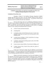
Pursuant to the Team Clean's recommendation in August 2003, Planning<br />
Department was requested to promote better layout of building blocks in the city<br />
through examination of stipulation of air ventilation assessment as one of the<br />
considerations for all major development or redevelopment proposals and in<br />
future planning. Accordingly, the "Feasibility Study for Establishment of Air<br />
Ventilation Assessment System" (the AVA Study) was conducted and completed<br />
in 2005. Air ventilation assessment becomes a protocol to objectively measure<br />
the effects of planning and development proposals on external air movement for<br />
achieving an acceptable macro wind environment.<br />
A technical guide on the performance-based AVA methodology and a set of<br />
qualitative guidelines to achieve better air ventilation objectives recommended in<br />
the AVA Study was promulgated in 2006. The HKPSG has also been revised to<br />
incorporate the guidelines on air ventilation since 2006.<br />
Computational fluid dynamics (CFD) is a branch of fluid mechanics using<br />
numerical methods and algorithms to solve and analyze problems that involve<br />
fluid flows. Computers are used to perform the millions of calculations required<br />
to simulate the interaction of fluids and gases with the complex surfaces used in<br />
engineering.<br />
The total projected length of facade of a building or a group of buildings if any<br />
separation in-between is less than 15m. (See Figures 2 & 3 of Appendix B)<br />
Grass paver Paving block having not less than 50% of floor area for the growth of grass.<br />
Greenery area Area planted with trees, shrubs, annuals, groundcovers, climbers, grasses and<br />
other types of living plants. Other greening features including water features,<br />
grass paver, vertical greening and landscape-treated slopes/retaining structures<br />
with gradient steeper than 45 degree may be accepted as described in Appendix<br />
F.<br />
Pedestrian zone/Greenery<br />
area at pedestrian zone<br />
Permeability (P) of<br />
buildings<br />
To enhance in particular the environmental quality at pedestrian level, greenery<br />
area that:<br />
i. abuts or has visual connection with a street or public pedestrian way/public<br />
open space accessible from a street, and the top soil level, or the top level<br />
of the frame or stack in the case of vertical greening, is within a level upto<br />
15m above such street (see Figure 1 of Appendix E), and/or<br />
ii. is provided at ground level or levels easily accessible to pedestrians which<br />
includes greenery areas at street level and at level above street if such level<br />
is accessible to pedestrians directly from a street.<br />
The percentage area ratio obtained by dividing the sum of the elevational areas of<br />
all accountable intervening space between buildings, intervening space between<br />
buildings and boundary lines, intervening space between buildings and centre<br />
line of adjoining streets and permeable elements within, above, below or between<br />
buildings by the sum of the elevational areas of the buildings and the aforesaid<br />
intervening spaces and permeable elements, when projected onto a chosen<br />
projection plane. (See Figures 9 to 14 of Appendix B)<br />
Site Coverage of Greenery The percentage of total greenery area divided by the area of the site.<br />
Site permeability For better urban air ventilation in a dense, hot-humid city, breezeways and air<br />
paths should be provided in order to allow effective air movements into the urban<br />
area to remove heat, gases and particulates and to improve the micro-climate of<br />
urban environment. Within individual development sites, higher permeability will
help improve air ventilation. The provision for higher permeability of building<br />
masses can be achieved by creating gaps between building blocks, between the<br />
podium and the building blocks built atop (i.e., a void podium deck), set back<br />
from street, and within building blocks at various levels, etc.<br />
Street Street means a street vested in the Government and maintained by the Highways<br />
Department or a private street on land held under the same Government lease as<br />
the site and under the terms of the lease, the lessee has to surrender (when<br />
required to do so) the land on which the street is situated to the Government, as<br />
described under B(P)R18A(3)(a)(i) & (ii).<br />
Street canyon A street canyon is a canyon (a deep narrow valley) formed in a street between<br />
tall buildings on both sides. The important geometrical feature of a street canyon,<br />
aspect ratio (H/W), is the major parameter influencing air ventilation between the<br />
buildings, where H and W are the height of buildings and the width of a street<br />
respectively. For canyons aspect ratio higher than 2, the air flow above building<br />
height will become highly difficult to reach the pedestrian level where the<br />
buildings are tightly packed to form a narrow street, especially when the flow is<br />
perpendicular to the axis of the canyon. (See method of measurement of width of<br />
street canyon (U) Figures 4-7 of Appendix B)<br />
Vertical greening Greenery that grows on a vertical surface abutting a street or public pedestrian<br />
way/public open space accessible from a street, and the top level of the frame or<br />
stack is within a level upto 15m above such street (See Figure 1 of Appendix E).<br />
Climbing and/or weeping plants along a frame mounted on the external walls of a<br />
building, or other suitable plants on a stack of modular planters or panels that are<br />
firmly fixed on permanent structures, or a combination of both are considered as<br />
vertical greening for the purpose of compliance with the site coverage of<br />
greenery requirements.<br />
- 2 -
Measures for Compliance with the Building Set Back Requirement<br />
15m<br />
Building structure above<br />
*Communal podium garden<br />
Min. 7.5m set back<br />
(a)<br />
B.L.<br />
C/<br />
L<br />
street<br />
street<br />
Width<br />
of street (a)<br />
Min. 7.5m set back<br />
Site Site<br />
B.L. B.L.<br />
Fig. 1 Building set back as detailed in paragraph 13(a)<br />
15m<br />
Greenery on communal<br />
podium garden<br />
Inclined plane = 1/1<br />
B.L. of opposite site<br />
- 1 -<br />
≥ Min. 7.5m (w) x 15m (H) sectional area<br />
Appendix D<br />
(PNAP <strong>APP</strong>-<strong>152</strong>)<br />
Fig. 2 Stepped building profile with communal podium garden as detailed in paragraph<br />
13(b)<br />
Note: * Communal podium garden shall comply with height, openness, size and greenery area requirements<br />
stipulated in paragraph 1(d) of Appendix A of JPN1<br />
/Measures …
Measures for Compliance with the Building Set Back Requirement (contd.)<br />
15m<br />
Building structure above<br />
* Communal podium garden<br />
Podium<br />
(a)<br />
B.L. B.L. of opposite site<br />
Note: * Communal podium garden shall comply with height, openness, size and greenery area requirements<br />
stipulated in paragraph 1(d) of Appendix A of JPN1<br />
- 2 -<br />
street<br />
Width<br />
of street (a)<br />
Inclined plane = 1/1<br />
Fig. 3 Stepped building profile with communal podium garden as detailed in<br />
paragraph 13(b)
Greenery Area at Pedestrian Zone<br />
Planter<br />
Fig. 1 Greenery at pedestrian zone may be covered as detailed in paragraph 19(a)<br />
- 1 -<br />
Width of<br />
planter (w)<br />
≥ 8w<br />
≤15m<br />
Street or public<br />
pedestrian way/ public<br />
open space connecting to<br />
a street<br />
Appendix E<br />
(PNAP <strong>APP</strong>-<strong>152</strong>)
Method of Measurement for Compliance with Site Coverage of Greenery<br />
- 1 -<br />
Appendix F<br />
(PNAP <strong>APP</strong>-<strong>152</strong>)<br />
1.1 All greenery areas shall be measured horizontally based on the soil 1 areas as shown<br />
on the plan, except as described in paragraph 1.2 below.<br />
1.2 Other greening features may be accepted to contribute not more than 30% of the<br />
total required greenery areas, subject to its location and application of a reduction<br />
factor where applicable, as detailed below: -<br />
Greening Features Location Reduction<br />
Factor in<br />
Computing<br />
the Greenery<br />
2 Water features Pedestrian zone;<br />
uncovered communal<br />
podium roof<br />
Areas<br />
50%<br />
Grass paver No restriction 50%<br />
3 Vertical greening Pedestrian zone Not applicable<br />
4 Landscape-treated<br />
slopes/retaining<br />
structures with gradient<br />
steeper than 45 o<br />
No restriction Not applicable<br />
Site coverage<br />
of greenery<br />
Not more than<br />
30% of the<br />
total greenery<br />
areas specified<br />
in Table 2<br />
1.3 Greenery in removable pots/planters that are not permanently fixed or built into the<br />
development is not accountable.<br />
Notes<br />
1. For reference, the recommended minimum soil depths for trees, shrubs, grass/ground<br />
covers are 1.2m, 0.6m and 0.3m respectively.<br />
2. Water features shall be measured by the horizontal water surface area. Swimming<br />
pool and jacuzzi are not considered as water features.<br />
3. Vertical greening shall be measured by the elevational area of the vertical frame (for<br />
climbing and/or weeping plants) or the elevational area of the modular planter or<br />
panel where the greenery will grow. For the avoidance of doubt, the horizontal area<br />
of soil in planters under the vertical frame/modular planter/panel already counted for<br />
vertical greening as aforesaid shall be excluded from the greenery area calculation.<br />
Self-clinging climbing plants on hard surfaced walls shall be measured horizontally<br />
based on the soil areas as shown on the plan (not counted as vertical greening and<br />
therefore not subject to the restriction in paragraph 1.2 above).<br />
4. Landscape-treated slopes/retaining structures shall be measured by the elevational<br />
area of the soil where the greenery will grow, and where the gradient of the slope<br />
varies, an averaged gradient may be accepted. For the avoidance of doubt, landscapetreated<br />
slopes/retaining structures with gradient equal or less than 45 degrees is not<br />
subject to the above restriction and will be measured horizontally based on the soil<br />
area as shown on the plan.
Information and Documents to be Submitted<br />
- 1 -<br />
Appendix G<br />
(PNAP <strong>APP</strong>-<strong>152</strong>)<br />
To demonstrate compliance with the building separation, building set back and<br />
site coverage of greenery requirements, the following information shall be provided for<br />
consideration: -<br />
Building Separation<br />
(a) 1:1000 layout plans each showing the site in relation to its adjoining streets<br />
and surrounding buildings and features. The footprint (external walls) of the<br />
proposed buildings within the site, the provided intervening spaces, permeable<br />
elements, the selected orthogonal projection planes, air corridors and air paths<br />
are to be clearly shown to demonstrate compliance with the building<br />
separation requirements for each low, middle and high zones.<br />
(b) 1:500 plans, elevations, sections and calculations showing the street canyon(s)<br />
(U), the maximum continuous projected façade length (Lp) of building(s) and<br />
group(s) of buildings in comparison to the permissible Lp; the separating<br />
distance (S) provided in comparison to the required S; and the permeability (P)<br />
of buildings achieved at each low, middle and high zone, in comparison to the<br />
minimum P.<br />
Building Set Back<br />
(c) A block plan showing the location of the subject site and the width of all<br />
adjoining streets;<br />
(d) Where the width of any street is less than 15m, further details such as level(s)<br />
of the street for computing the amount of required set back.<br />
(e) 1:200 plan(s) and section(s) with calculations demonstrating compliance with<br />
the building set back requirements.<br />
(f) Information showing the compliance of greenery areas requirement under<br />
paragraph 15(b) of this PNAP is detailed in items (g) to (i) below.<br />
Site Coverage of Greenery<br />
(g) 1:500 plan(s) showing the locations of the proposed greenery areas, the<br />
common access thereto and details of relevant street, public pedestrian way,<br />
public open space for compliance with the requirement of greenery areas at<br />
pedestrian zone(s).<br />
(h) A schedule with calculations and illustrated diagrams showing the area of<br />
proposed greenery at each location for compliance with the requirements in<br />
Table 2.<br />
(i) Location of irrigation point(s) and drainage provision.
- 1 -<br />
Appendix H<br />
(PNAP <strong>APP</strong>-<strong>152</strong>)<br />
Format of the AVA Register for Private/Quasi-Government Projects<br />
(Extracted from Annex C of HPLB Technical Circular No. 1/06, Air Ventilation<br />
Assessment)<br />
1. Project Title<br />
2. Project Reference<br />
3. Project Proponent<br />
4. Outline of Project<br />
Details<br />
(attach location plan)<br />
AVA Register for<br />
Private/Quasi-Government Projects<br />
Project Description<br />
Page 1 of Appendix H
5. Select the following category(ries) which would be applicable to the project :<br />
Comprehensive land use restructuring schemes, including schemes that<br />
involve agglomeration of sites together with closure and building over of<br />
existing streets.<br />
Area-wide plot ratio and height control reviews.<br />
Developments on sites over 2 hectares and with an overall plot ratio of 5 or<br />
above.<br />
Development proposals with total Gross Floor Area exceeding 100,000<br />
square metres.<br />
Developments with podium coverage extending over one hectare.<br />
Development above public transport terminus.<br />
Buildings with height exceeding 15 metres within a public space or<br />
breezeway designated on layout plans / outline zoning plans or proposed by<br />
planning studies.<br />
Undeveloped waterfront sites with lot frontage exceeding 100 metres in<br />
length.<br />
Extensive elevated structures of at least 3.5 metres wide, which abut or<br />
partially cover a pedestrian corridor along the entire length of a street block<br />
that has / allows development at plot ratio 5 or above on both sides; or<br />
which covers 30% of a public open space.<br />
Others, please specify<br />
_____________________________________________<br />
- 2 -<br />
Page 2 of Appendix H
6. Details of the AVA conducted for the project<br />
(The AVA report, 3 hard copies and an electronic copy in Acrobat<br />
format, is to be attached for record)<br />
(a) AVA Consultants (if any)<br />
(b) Time (start / finish)<br />
(c) Assessment tool used (CFD or wind<br />
tunnel)<br />
(d) What were the major changes to the<br />
design of the project resulting from the<br />
AVA?<br />
7. Disclosure of information to the public<br />
Does the project proponent consent to<br />
release the AVA report for public<br />
inspection?<br />
Does the project proponent consent to<br />
release information in this AVA proforma<br />
for public inspection?<br />
8. Contact<br />
(a) Name<br />
(b) Designation<br />
(c) Tel.<br />
(d) E-mail<br />
- 3 -<br />
Yes<br />
No<br />
Yes<br />
No<br />
Page 3 of Appendix H
Building Separation Requirement<br />
1. Assessment and Method of Measurement<br />
- 1 -<br />
Appendix B<br />
(PNAP <strong>APP</strong>-<strong>152</strong>)<br />
1.1 The design of building(s) above Level Zero (the mean street level on which the<br />
site abuts or where the site abuts on streets having different levels, the mean level of the<br />
lower or lowest street) of the site shall comply with the Design Requirements (1) and (2)<br />
below. They shall be assessed separately for each of the three assessment zones i.e. the<br />
low, middle and high zones as described in paragraph 7 of this PNAP.<br />
1.2 All measurements are taken from the external walls of the building. Building<br />
features that will not materially affect air ventilation around buildings, including single<br />
storey bridges that are open on both sides and provided with perforated railings, signboards,<br />
minor projecting features, open sided features such as balconies, utility platforms, covered<br />
walkways and trellises and other highly permeable features such as railing (with free area ≥<br />
2/3 or equivalent) may be disregarded in the building separation assessment. Individual<br />
noise barriers that are not extensive in height and designed to permit air flow through or<br />
over the barriers may also be disregarded subject to the provision of appropriate building<br />
features or permeable elements such as communal podium gardens to compensate for the<br />
barrier’s obstruction to free air flow to the satisfaction of the BA. For the avoidance of<br />
doubt, buildings acting as noise barriers cannot be disregarded in the building separation<br />
assessment.<br />
1.3 Effect on air ventilation around buildings due to topographical features within a<br />
site including any slope features and retaining walls may be disregarded. Any parts of a<br />
building that are below the site topography may therefore be disregarded (see Figure 1).<br />
Design Requirement (1) - Continuous Projected Façade Length (Lp) of building(s)<br />
abutting a street<br />
2.1 This requirement controls the maximum (Lp) of a building or a group of<br />
buildings if any part of the building is within 30m from the centreline of the street on<br />
which the building(s) abuts.<br />
2.2 Subject to paragraphs 2.3, 2.4 and 2.5 below, the (Lp) of a building or a<br />
group of buildings along its long side shall not exceed the maximum permissible Lp which<br />
is obtained by multiplying 5 and the mean width of the street canyon(U) on which the<br />
building(s) abuts. The width of such a street canyon is measured perpendicular to the<br />
centreline of the street from the external wall of the building, that is vertically unobstructed<br />
within the assessment zone and within 30m from the centreline of the street, to the lot<br />
boundary of the other site on the opposite side of the street (see Figures 2 to 6). If the<br />
building or group of buildings abuts two or more streets having different (U), the least (U)<br />
shall be adopted.<br />
/2.3 …
2.3 If the width of a street canyon varies (on plan), (U) is the width obtained by<br />
dividing the area of such a street canyon by its length as measured along the centreline of<br />
the street. If only a part of the building is within 30m from the centreline of the street, (U)<br />
is the mean width of the street canyon that abuts such part of the building. If there is more<br />
than one such street canyon along the same street, (U) is the width obtained by dividing<br />
the sum of the areas of such street canyons by the sum of the lengths, as measured along<br />
the centreline of the street, of such street canyons. (see Figure 7)<br />
2.4 For the purpose of measuring individual Lp of a building or a group of<br />
buildings along its long side, the part of the building(s) that is within the low zone and of a<br />
height of not more than 6.67m (1/3 of 20m which is the height of the low zone) may be<br />
disregarded.<br />
2.5 This Design Requirement on the maximum permissible Lp may not be<br />
applicable under the following circumstances:<br />
(a) If the site does not abut a street;<br />
(b) If no building is within 30m from the centreline of any streets on which the site<br />
abuts;<br />
(c) If no parts of the building within an assessment zone is within 30m from the<br />
centreline of any streets on which the site abuts, this Design Requirement may<br />
not be applicable to such parts of the building within the assessment zone only;<br />
or<br />
(d) If there are such other special circumstances rendering the control on the<br />
maximum permissible Lp undesirable or unnecessary, as may be accepted by<br />
the BA.<br />
For the avoidance of doubt, compliance with the following Design<br />
Requirement (2) is still required unless otherwise exempted.<br />
Design Requirement (2) - Separating Distance (S) & Permeability (P) of Buildings<br />
3. Projection Planes for Assessment<br />
3.1 Subject to paragraph 3.3 below, assessment on compliance with the Design<br />
Requirement (2) shall be made through a pair of vertical projection planes (x, y) at an<br />
orthogonal relationship to each other. (see Figure 8) At least one of the projection planes<br />
for the low zone shall be set parallel to a street on which the site abuts. For a site that abuts<br />
on a curvilinear street, the projection plane for the low zone shall be set along any tangent<br />
of the street. For the middle/high zones, such pair of projection planes may be set to suit<br />
the building disposition or the site wind environment.<br />
3.2 To allow more flexibility in building design, the angle between each pair of<br />
projection planes may vary from 75 to 105 degrees.<br />
3.3 For a site that is less than 2 hectares, assessment on compliance with the Design<br />
Requirement (2) may only be required on one projection plane (instead of a pair), if the<br />
total width of all projected building facades as projected onto the other projection plane is<br />
less than 60m.<br />
/4. …<br />
- 2 -
4. Separating Distance (S) & Permeability (P) of Buildings<br />
4.1 Subject to paragraphs 4.6 and 4.7 below, elevation of all buildings within the<br />
site shall be projected onto the chosen projection planes. On each projection plane, the<br />
required permeability (P) of buildings as stipulated in Table 1 of this PNAP shall be<br />
achieved (see Figure 9).<br />
4.2 Not less than 2/3 of the required (P) shall be provided by intervening spaces.<br />
All intervening spaces shall be open to above or of a clear height of not less than 2/3 of the<br />
assessment zone. There shall be intervening space(s) between the ends of the projected<br />
building facades and the adjacent site boundaries or where the site abuts a street or a lane 1 ,<br />
the centreline of such adjoining street or lane. Such intervening space(s) as projected onto<br />
the chosen projection plane shall have a separating distance (S) of not less than 7.5m wide.<br />
If the distance between the end of a projected building facade and the boundary line or the<br />
centreline of the adjoining street / lane varies on plan, the mean (S) shall not be less than<br />
7.5m subject to no part of the building be within 3m from the boundary line. (See Figures<br />
10 to 12) If such intervening spaces are not sufficient to meet 2/3 of the required (P),<br />
buildings shall also be separated by intervening spaces. Intervening space(s) between 2<br />
projected building facades shall have an (S) of not less than 15m wide.<br />
4.3 Not more than 1/3 of the required (P) may be provided by permeable elements.<br />
Permeable elements may be provided within, above, below or between buildings e.g.<br />
refuge floors, communal sky gardens etc. (see Figures 13 & 14)<br />
4.4 The minimum clear width / height of all permeable elements as projected onto<br />
the chosen projection plane is 3m.<br />
4.5 To allow more design flexibility, the projected façade of the intervening space<br />
between buildings and between buildings and the boundary lines within an assessment<br />
zone may follow the path of a notional air corridor that starts at 90 degrees from the<br />
projection plane (on plan). The air corridor may flow between buildings and may change<br />
direction without changing its width, when it meets the boundary line or anywhere within<br />
the site, by not more than 15 degrees provided the direction of the air corridor after the<br />
change of course is always within 15 degrees from its original path before it enters the site.<br />
The minimum width of the air corridor along its path between buildings shall not be less<br />
than 15m. (See Figures 15 to 18).<br />
4.6 When the site is large and / or of irregular shape, the site may be subdivided<br />
into two or more notional sites provided that the line of the sub-divisioning is located along<br />
the centreline of a notional wind path that complies with the following requirements:<br />
(a) the wind path is open to above from the lowest level of the subject assessment<br />
zone;<br />
(b) it is of a width of not less than 15m;<br />
- 3 -<br />
/(c) …<br />
1 Open space outside the site boundary is not accountable for (P). However, where an area is zoned as open<br />
space on the Outline Zoning Plan / Development Permission Area Plan and provided such area is<br />
designated as promenade or non-building area on the relevant town plan, such area may be treated as a<br />
lane for the purpose of assessing (S) and (P).
(c) it is continuous across the site in one direction or it may change in direction by<br />
not more than 15 degrees provided its direction after the change of course is<br />
always within 15 degrees from its original path 2 ;<br />
(d) where it meets the site boundaries, there is a street or lane with a mean width of<br />
not less than 7.5m.<br />
4.7 After subdividing the site, the (P) may be assessed separately for each<br />
subdivided site using the same or a different pair of orthogonal projection planes. (see<br />
Figures 19 & 20)<br />
4.8 A sample case on assessment of building separation provisions is given in<br />
Appendix C.<br />
5. Performance-based Design Alternative on the Provision of (P)<br />
5.1 Subject to compliance with the minimum permeability (P) of buildings as<br />
specified in Table 1 and paragraph 7 of this PNAP and satisfactory demonstration by<br />
applying air ventilation assessment (AVA) that the buildings’ potential impact on the local<br />
wind environment has been duly considered and that by comparing with a baseline case<br />
which complies with the above Design Requirements, the proposed design is equivalent or<br />
better in external air ventilation terms, the BA is prepared to accept alternative designs that<br />
do not comply with the prescriptive requirements specified in Design Requirement (1) and<br />
paragraphs 4.2 and 4.3 of Design Requirement (2) above.<br />
5.2 The air ventilation assessment shall be properly done by referring to the latest<br />
methodology and requirements of Technical Circular No. 1/06 on Air Ventilation<br />
Assessments 3 using wind tunnel modelling or digital representation of the physical and<br />
wind environment using CFD simulations.<br />
5.3 For projects adopting a performance-based design alternative, the following<br />
information with full justifications for deviation from the prescribed requirements shall be<br />
submitted in two stages:<br />
Stage 1 Submission<br />
(a) An expert evaluation on whether the tools and methodologies for AVA<br />
employed are fit for the purpose and are suitably verified and scientifically<br />
validated with practical merits shall be carried out. In this connection,<br />
submission for prior acceptance of all information listed below covering factors<br />
like site configuration, local topography, wind characteristic and sensitive<br />
receivers in the surrounding areas, relevant urban climatic considerations, etc. is<br />
required:<br />
- 4 -<br />
/(i) …<br />
2 The wind path should preferably align with the summer prevailing wind direction or existing street pattern.<br />
3 The Technical Circular No 1/06 issued by the Housing, Planning and Lands Bureau is available from the<br />
website at http://www.devb.gov.hk/filemanager/en/content_679/hplb-etwb-tc-01-06.pdf
(i) a baseline case that fully complies with all the prescriptive Design<br />
Requirements (1) and (2);<br />
(ii) details of scientific bases to assess performance;<br />
(iii) analysis tools and/or design procedures;<br />
(iv) modeling input, settings and parameters for the analysis and/or design;<br />
(v) limitation and applicability of the proposal in context;<br />
(vi) interpretation of results;<br />
(vii) method of verification;<br />
(viii) similar established standard and implementation in other places; and<br />
(ix) documented references of the scientific bases.<br />
Stage 2 Submission<br />
(b) A study report on whether the proposed scheme will be in line with urban<br />
climatic considerations and such similar requirements as imposed through the<br />
town planning approval process or in Government lease; and<br />
(c) An AVA report on whether the proposed scheme will perform better in external<br />
air ventilation terms, demonstrated by the simulation results of the proposed<br />
scheme as compared to the simulation results of the baseline case.<br />
5.4 Upon approval of the proposal, additional three hard copies and an electronic<br />
copy in Acrobat format for each AVA report shall be submitted together with a copy of the<br />
completed AVA register (Appendix G) for uploading to the AVA register as detailed in<br />
paragraph 26 of the PNAP.<br />
- 5 -
Max.<br />
Bldg Ht<br />
60m(H)<br />
20m(H)<br />
Level 0<br />
Site Topography & Sunken Buildings<br />
• Site “Level Zero” is the mean level of the lower or lowest street(s)<br />
• The height of a building shall be measured to the mean height of the roof over the highest usable floor space<br />
• Disregard any building below Level Zero or any sunken part of a building<br />
• Disregard the effect on air ventilation around buildings due to topographical features of the site<br />
CL of adjoining<br />
street/ lane<br />
Tower 1 Tower 2 Tower 3 & 4 Tower 5<br />
B.L.<br />
High Zone<br />
Middle Zone<br />
Low Zone<br />
Elevational Projection (across the entire site)<br />
Appendix B<br />
(PNAP <strong>APP</strong>-<strong>152</strong>)<br />
Common<br />
B.L.<br />
Fig. 1
Individual "Continuous Projected Façade Length (Lp)"<br />
The total projected length of façade of a building or a group of buildings if any separation in-between<br />
is
(Lp) = 80m<br />
Individual (Lp) of a building or group of buildings along its long side<br />
20m<br />
30m<br />
50m<br />
(Lp)=70m<br />
20m 10m 30m<br />
(Lp)=60m<br />
20m<br />
30m<br />
50m<br />
20m 10m 30m<br />
70m<br />
10m<br />
10m<br />
≥15m<br />
20m<br />
10m<br />
20m<br />
10m<br />
20m<br />
(Lp)=50m<br />
L1, (Lp) = L1<br />
• A notional rectangle for measuring (Lp) of a building or a group of buildings along its long side.<br />
• Where the building or group of buildings is irregular in shape, the notional rectangle may be the<br />
smallest rectangle that contains the building or group of buildings<br />
L2<br />
Width of Adjoining Street Canyon (U)<br />
Distance from the external wall of a proposed building to the B.L. of the opposite site(s)<br />
across the street<br />
• street canyon shall be vertically unobstructed. Signboards, minor projecting features,<br />
open sided features e.g. balconies, utility platforms, covered walkways and trellises<br />
may be disregarded.<br />
Opposite Lot B.L.<br />
Fig. 4
Adjoining Street Canyon<br />
Buildings subject to control on<br />
individual (Lp)<br />
• buildings/groups of buildings wholly or<br />
partly within 30m from the centreline<br />
of an adjoining street.<br />
Fig. 5
Mean Width of Adjoining Street Canyon (U) & Max.<br />
Individual (Lp)<br />
Max. (Lp) = 5 x (U)<br />
• If the building abuts two or more<br />
streets, the lesser or least (U)<br />
• Building A<br />
U3 U3<br />
A<br />
A < < U1 U1<br />
A<br />
A ; ; max. max. (Lp)(A) (Lp) A = = 5 5 x x U3 U3A A<br />
• Building B<br />
U1B < U2B ; max (Lp) B = 5 x U1B Fig. 6
Mean Width of Street Canyon (U)<br />
Building A<br />
When width of the adjoining street canyon<br />
varies, the mean width of (U) shall be<br />
determined as:<br />
Street Canyon Area (A1)<br />
U A1 = ------------------------------------------<br />
Length (A1)<br />
• When U A1 < U A2 , max. (Lp) A = 5 x U A1<br />
STREET 1<br />
Adjoining Lot<br />
STREET 2<br />
A1<br />
A2(a)<br />
Building A<br />
Street Canyon Area [A2(a) + A2(b)]<br />
U A2 = ----------------------------------------------------<br />
Length [A2(a) + A2(b)]<br />
A2(b)<br />
S ≥15m<br />
Building B<br />
No part of the building is closer than 30m to the<br />
street centrelines. Building B is not subject to the<br />
Design Requirement on (Lp).<br />
Building C<br />
(Lp) is determined by the width of (U) at Street 2:<br />
• (Lp) C = 5 x U C2<br />
Building<br />
B<br />
B.L.<br />
S ≥15m<br />
Building C<br />
C2<br />
30m<br />
Street Canyon Area (C2)<br />
U C2 = -------------------------------<br />
Length (C2)<br />
C L<br />
30m 30m<br />
C L<br />
Opposite Lot B.L.<br />
Fig. 7
A pair of Projection Planes for (P) assessment<br />
Low Zone Middle/Upper Zone<br />
Adj.<br />
Lot<br />
75-105 o<br />
75-105 o<br />
• Low Zone<br />
- one of the planes parallel to an adjoining street<br />
• Middle/High Zone<br />
- any pair chosen to suit the building disposition or environmental context e.g. prevailing wind direction<br />
• (P) assessment on one plane only if:<br />
(a) site < 2ha, and<br />
(b) the total width of all projected building facades as projected onto the other plane
Max.<br />
Building<br />
Height<br />
60m(H)<br />
20m(H)<br />
Level 0<br />
Permeability (P) of Buildings<br />
(P) is the percentage area ratio of the sum of projected intervening spaces & permeable elements<br />
over individual assessment zone on a projection plane<br />
(P)<br />
Sum of areas of intervening spaces & permeable elements<br />
= ----------------------------------------------------------------------------------- X 100%<br />
Area of the assessment zone<br />
CL of adjoining<br />
Common<br />
street/lane<br />
B.L.<br />
Tower 1 Tower 2 Tower 3 & 4 Tower 5<br />
B.L.<br />
High Zone<br />
Middle Zone<br />
Low Zone<br />
Low Zone<br />
Elevational Projection (across the entire site)<br />
Common B.L.<br />
Fig. 9
Max.<br />
Building<br />
Height<br />
60m(H)<br />
20m(H)<br />
Level 0<br />
Permeability (P) of Buildings – Intervening Spaces<br />
C L<br />
Intervening spaces shall account for min. 2/3 of the required (P)<br />
Sum of areas of intervening spaces<br />
-------------------------------------------------- x 100% ≥ 2/3 x<br />
Area of the assessment zone<br />
of adjoining<br />
street/lane<br />
(P)<br />
Tower 1 Tower 2 Tower 3 & 4 Tower 5<br />
Low Zone<br />
B.L.<br />
High Zone<br />
Middle Zone<br />
≥ 2/3H L<br />
≥ 2/3H L<br />
Intervening Space<br />
Provision of intervening spaces with separating distance (S) between projected facades ≥ 15m, and<br />
between end of a projected façade and adjacent common B.L. or centreline of adj. street/lane ≥ 7.5m<br />
• Height of such intervening space ≥ 2/3H of the Assessment Zone, or<br />
• It is open to above<br />
Centreline of adjoining<br />
street/lane<br />
≥ 7.5m<br />
I.S.<br />
B.L.<br />
I.S./<br />
P.E.<br />
Projected<br />
Building<br />
Façade (A)<br />
Mean Width of Separating Distance<br />
Mean width between projection line at building ends to common B.L. or centreline of street/lane<br />
Projection Plane X<br />
C L<br />
≥7.5m<br />
C L<br />
Assessment Zone (W)<br />
S1<br />
(Lp)AG S2<br />
(Lp)B<br />
S3<br />
Building Group<br />
A G<br />
≥15m<br />
STREET 1<br />
STREET 2<br />
Building<br />
B<br />
≥3m<br />
Area (D)<br />
S3 = ------------------ (≥ 7.5m)<br />
Length (D)<br />
Plan<br />
D<br />
Area (D)<br />
Fig. 12
Max.<br />
Building<br />
Height<br />
60m(H)<br />
20m(H)<br />
Level 0<br />
Permeability (P) of Buildings – Permeable Elements<br />
C L<br />
Permeable elements may contribute to maximum 1/3 of the required (P)<br />
Sum of areas of permeable elements<br />
------------------------------------------------------- x 100% ≤ 1/3 x (P)<br />
Area of the assessment zone<br />
of adjoining<br />
street/lane<br />
Tower 1 Tower 2 Towers 3 & 4 Tower 5<br />
B.L.<br />
High Zone<br />
Middle Zone<br />
Low Zone<br />
Elevational Projection (across the entire site)<br />
Common<br />
B.L.<br />
Common B.L.<br />
Fig. 13
Permeable Elements<br />
Provision of permeable elements within, above, below or between buildings<br />
• clear opening size of such a permeable element is not less than 3m<br />
Centreline of adjoining<br />
street/lane<br />
≥7.5m<br />
B.L.<br />
P.E.<br />
Design Flexibility notional air corridor / wind path<br />
• Change in direction ≤ 15º when it meets the boundary line or anywhere within the site<br />
• Direction deviate ≤ 15º from the original path<br />
• Width of the intervening space / notional air corridor / wind path remains unchanged after<br />
such change in directions<br />
Fig. 15
Notional Air Corridor Separating distance (S) between buildings & at façade ends<br />
Projection Plane X(1)<br />
C L<br />
≥ 7.5m<br />
• When projection plane X is placed on either side of the site, length of a building façade so projected on the planes may vary.<br />
• (P) assessment may be based on the projection on either one of the planes X(1) or X(2) as chosen.<br />
• separating distance (S) between buildings ≥15m.<br />
• mean separating distance between the facade end and adjacent common B.L. or centreline of adj. street/lane ≥7.5m subject<br />
to the condition that no part of the building be closer than 3m from the common B.L. with adjoining lot.<br />
C L<br />
Common B.L.<br />
S1 S2<br />
S3<br />
S1 (Lp) A2<br />
S2<br />
Projection Plane X(2)<br />
(Lp) A1<br />
Opposite Lot B.L.<br />
≤15 o<br />
Assessment Zone (W) 2<br />
Assessment Zone (W) 1<br />
≤15 o<br />
≥15m<br />
(Lp) B1<br />
STREET 1<br />
STREET 2<br />
(Lp) B2<br />
≤15 o<br />
S3<br />
≥ 3m<br />
Common B.L.<br />
Opposite Site B.L.<br />
Area (D)<br />
S3 = ----------------<br />
Length (D)<br />
D<br />
Area (D)<br />
Plan<br />
Fig. 16
Projection Plane Y(1)<br />
Notional Air Corridor Separating distance at façade ends<br />
• When projection plane Y is placed on either side of the site, length of a building façade so projected on the planes may vary.<br />
• (P) assessment may be based on the projection on either one of the planes Y(1) or Y(2) as chosen.<br />
• mean separating distance between the facade end and centreline of the adjoining street/lane ≥ 7.5m subject to the condition<br />
that no part of the building be closer than 3m from the common B.L. with adjoining lot.<br />
S1 S2<br />
Assessment Zone (W) L<br />
(Lp) L<br />
≤15 o<br />
Common B.L.<br />
Opposite Lot B.L.<br />
STREET 2<br />
Opposite Lot B.L.<br />
≤15m<br />
D2<br />
Plan<br />
D1<br />
≤15 o<br />
Area (D)<br />
S = ---------------- (≥ 7.5m)<br />
Length (D)<br />
STREET 1<br />
Common B.L.<br />
Area (D)<br />
≤15 o<br />
S2<br />
(Lp) R<br />
S1<br />
Assessment<br />
Zone (W) R<br />
Projection Plane Y(2)<br />
Fig. 17
Notional Air Corridor Separating distance at façade ends<br />
• Mean separating distance (S) between the facade end and common B.L. or centreline of the<br />
adjoining street/lane ≥ 7.5m subject to the condition that no part of the building shall be closer<br />
than 3m from the common B.L. with adjoining lot.<br />
• When the site abuts two adjoining streets • When the site abuts a street and an adjoining lot<br />
Fig. 18
Wind Path passing through the site<br />
Dividing the site into TWO or more notional sites for (P) assessment<br />
• vertically uncovered and unobstructed above the lowest level of the assessment zone<br />
• width ≥ 15m<br />
• leading to a street or to a lane of mean width ≥ 7.5m at either ends<br />
Common B.L.<br />
“A” “B”<br />
Common B.L.<br />
Fig. 19
Projection Plane Y("A")<br />
Sub-divided Notional Sites for (P) Assessment<br />
• Separating distance (S) at the projected facade end shall be measured to the notional B.L.<br />
at centreline of the wind path.<br />
• Individual pair of projection planes may be chosen for each of the TWO sub-divided sites<br />
for (P) assessment.<br />
• Site "Level Zero" of the original undivided site shall be used for all notional sites.<br />
Notional Site “A” Notional Site “B”<br />
Projection Plane Y ("B")<br />
≥ 7.5m<br />
Projection Plane X ("A")<br />
≥ 7.5m<br />
Projection Plane X("B")<br />
Plan<br />
Fig. 20
Building Separation Assessment<br />
Sample Case<br />
• Site area =1,920m 2 (< 20,000 m 2 )<br />
• Proposed building: one tower above a podium of 15m(H)<br />
• Max. building height = 78m (> 60m)<br />
• The site abuts a street of 15m wide<br />
• (Lp) of a podium with full site coverage = 80m( ≥60m, assessment required)<br />
78m(H)<br />
High Zone<br />
60m(H)<br />
Middle Zone<br />
20m(H)<br />
Low Zone<br />
Level 0<br />
15m<br />
Common B.L.<br />
Tower<br />
18 m 32 m 30 m<br />
Podium<br />
80m<br />
Projected Facade Through Projection Plane X<br />
Common B.L.<br />
Projection Plane X<br />
24m<br />
Street (15m)<br />
4m<br />
Tower<br />
80m<br />
Design Requirement (1)<br />
Max. (Lp) = 5 x U<br />
Appendix C<br />
(PNAP <strong>APP</strong>-<strong>152</strong>)<br />
U T<br />
Podium<br />
Building at Low Zone<br />
• UP = 15m, max. (Lp) P = UP x 5 = 75m<br />
• (Lp) of proposed podium = 80 m (> 75m )<br />
(i.e. NOT OK)<br />
Building at Middle/High Zone<br />
U P<br />
Adjoining<br />
Site<br />
• U T = 19m, max. (Lp) T = U T x 5 = 95m<br />
• (Lp) of proposed tower = 32m (< 95m )<br />
(i.e. OK)<br />
PLAN<br />
Fig. 1
Building Separation Assessment<br />
Design Requirement (2) - Low Zone<br />
• Minimum (P) = 20% (from Table 1)<br />
• Set Projection Plane X parallel to the Street<br />
13.4m<br />
20m<br />
7.5m<br />
29.5m<br />
Podium<br />
80m<br />
13m<br />
22.5m<br />
Podium Garden/Roof<br />
Intervening space Permeable element<br />
7.5m<br />
Projected Facade Through Projection Plane X<br />
Projection Plane X<br />
24m<br />
Street (15m)<br />
7.5m 7.5m<br />
Tower<br />
80m<br />
4m<br />
Podium<br />
Intervening Space & Separating Distance<br />
• min. 7.5m to common B.L.<br />
• open to above, or of height ≥ 2/3 of the Assessment Zone<br />
• (Lp) P = 80m – (7.5m x 2) = 65m (< 75m, i.e. OK)<br />
Total facade area of the intervening spaces<br />
= (7.5x13.4)m 2 + (7.5x13.4 + 22.5x5)m 2 = 313.5m 2<br />
(P) achieved by the intervening spaces<br />
= 313.5m 2 / (20x80)m 2 x 100%<br />
= 19% (< 20%, but not less than (2/3) x 20% = 13.33%)<br />
Facade area of the permeable element<br />
= 13m x 5m = 65m 2<br />
(P) achieved by the permeable element<br />
= 65m 2 / (20x80)m 2 x 100%<br />
= 4% (< (1/3) x 20% = 6.66%, i.e. all accountable)<br />
Overall (P) achieved at low zone<br />
= 19% +4% = 23% (> 20%, i.e. OK)<br />
Adjoining Site<br />
Fig. 2
78m(H)<br />
60m(H)<br />
Building Separation Assessment<br />
Design Requirement (2) - Middle/High Zone<br />
High Zone<br />
Middle Zone<br />
20m(H)<br />
Level 0<br />
18m<br />
Intervening space<br />
Tower<br />
32m<br />
80m<br />
30m<br />
Podium Garden/Roof<br />
Projected Facade Through Projection Plane X<br />
Projection Plane X<br />
24m<br />
Street (15m)<br />
7.5m 7.5m<br />
Tower<br />
80m<br />
4m<br />
Podium<br />
Adjoining Site<br />
Intervening Space & Separating Distance<br />
• min. 7.5m to common B.L.<br />
• open to above or of height ≥ 2/3 of the Assessment Zone<br />
• (Lp) T = 32m(< 95m, i.e. OK)<br />
Total facade area of the intervening spaces<br />
= (18x58)m 2 + (30x58)m 2 = 2784m 2<br />
Overall (P) achieved<br />
= 2784m 2 / (80x58)m 2 x 100%<br />
= 60% (> 20%, i.e. OK)<br />
Fig. 3