

molded fiber prototypes and low-volume production - Fortus
molded fiber prototypes and low-volume production - Fortus
molded fiber prototypes and low-volume production - Fortus

Create successful ePaper yourself
Turn your PDF publications into a flip-book with our unique Google optimized e-Paper software.
MOLDED FIBER PROTOTYPES AND<br />
LOW-VOLUME PRODUCTION<br />
By Michael Mabie <strong>and</strong> Bill Camuel, Stratasys, Inc.<br />
OVERVIEW<br />
Since the 1930s, <strong>molded</strong> paper pulp has been used to make containers, trays <strong>and</strong> caps. Initially,<br />
<strong>molded</strong> pulp, which is also called <strong>molded</strong> fi ber, was only available for large <strong>volume</strong>, commodity<br />
products such as egg cartons, fruit trays <strong>and</strong> drink cup holders. Today, <strong>molded</strong> fi ber is a popular<br />
choice for both high <strong>volume</strong> containers <strong>and</strong> <strong>low</strong> <strong>volume</strong>, interior packaging (Figure 1).<br />
Fol<strong>low</strong>ing a decline that began in the 1970s, <strong>molded</strong> fi ber experienced a resurgence, fueled by<br />
environmental concerns, because it is a sustainable alternative to plastic packaging. Produced<br />
from old newsprint, corrugated boxes <strong>and</strong> a variety of other plant fi bers, <strong>molded</strong> fi ber packaging<br />
is 100 percent recyclable <strong>and</strong> biodegradable. It is also a cost effective packaging solution for<br />
20,000 to over 2,000,000 pieces annually. Other advantages include cost reductions from <strong>molded</strong><br />
fi ber’s <strong>low</strong> cost disposal, ease of packing <strong>and</strong> minimal warehousing requirements<br />
Molded fi ber provides excellent blocking <strong>and</strong> bracing functionality <strong>and</strong> is highly shock absorbent.<br />
For interior protective packaging, the relatively soft fi bers cushion products <strong>and</strong> absorb<br />
impact. An alternative to exp<strong>and</strong>ed polystyrene (EPS) foam, die cut corrugated <strong>and</strong> foam in place<br />
packaging, <strong>molded</strong> fi ber is widely used for electronics, household goods, automotive parts <strong>and</strong><br />
medical products (Figure 2). It is also an excellent choice for shipping <strong>and</strong> h<strong>and</strong>ling applications<br />
when used as an edge protector or pallet tray. Durable, fl exible <strong>and</strong> environmentally friendly,<br />
<strong>molded</strong> fi ber is used in a wide range of confi gurations for a variety of applications, including end<br />
caps, trays, cushions, <strong>and</strong> clamshells.<br />
Forming fi ber into a cap, tray or clamshell requires a mold through which a vacuum is pulled.<br />
While <strong>production</strong> of interior packaging is automated, quick <strong>and</strong> <strong>low</strong> cost, mold making is a timeconsuming<br />
<strong>and</strong> labor-intensive process. Needing cost reductions <strong>and</strong> rapid delivery of evaluation<br />
samples <strong>and</strong> short run custom orders, <strong>molded</strong> fi ber manufacturers are seeking reductions in time,<br />
labor <strong>and</strong> cost for the fabrication of forming molds. As demonstrated by leaders in the <strong>molded</strong><br />
fi ber industry, fused deposition modeling (FDM) provides the solution.<br />
FDM AND MOLDED FIBER<br />
Replacing the design, machining <strong>and</strong> screening processes of<br />
traditional mold build ing, FDM automates <strong>and</strong> accelerates<br />
mold <strong>production</strong>. What would take two to four weeks to<br />
complete can be fi nished in two to four days with only a<br />
few hours of labor (Table 1). Using FDM, fi ber molders can<br />
produce customer samples quickly <strong>and</strong> affordably. Since FDM<br />
fi ber forming molds have produced in excess of 30,000 pieces,<br />
the prototype tool transitions to a bridge to <strong>production</strong> solution<br />
for high <strong>volume</strong> work or the <strong>production</strong> tool for <strong>low</strong> <strong>volume</strong>,<br />
custom jobs.<br />
The International Molded Pulp Environmental Packaging<br />
Association (IMPEPA) classifi es four types of <strong>molded</strong> pulp.<br />
FDM has been successfully applied to the two most common,<br />
Type 1 <strong>and</strong> Type 2.<br />
Type 1—Thick Walled (Figure 4)<br />
• 3/16 to 1/2 inch (4.7 to 12.7 mm) walls.<br />
• Primarily used for support packaging applications.<br />
• Surfaces are moderately smooth on mold side <strong>and</strong> very rough on opposite side.<br />
Type 2—Transfer Molded (Figure 5)<br />
• 1/16 to 3/16 inch (1.6 to 4.7 mm) walls.<br />
• Typically used for packaging electronic equipment, cellular phones <strong>and</strong> household items.<br />
• Surfaces are moderately smooth on mold side <strong>and</strong> fairly smooth on transfer mold side.<br />
Time Required Cost Skill Level<br />
Process Lead-<br />
Time<br />
Traditional<br />
machining<br />
Cost<br />
3 weeks $10,000<br />
FDM 3 days $ 3,000*<br />
SAVINGS 12 days<br />
(80%)<br />
$ 7,000<br />
(70%)<br />
Table 1: Savings of 70% to 80% when<br />
machined tooling was replaced with<br />
FDM for a custom pulp fi ber protective<br />
packaging project. *Outsourced<br />
<strong>production</strong>.<br />
3D PRODUCTION SYSTEMS<br />
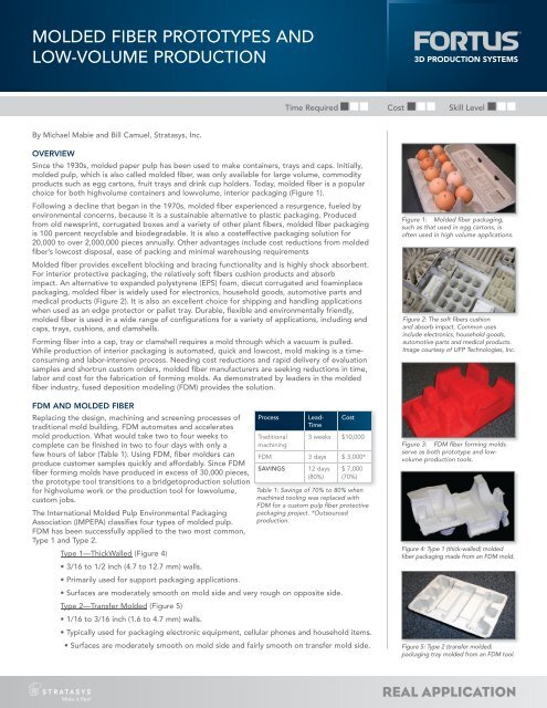
Figure 1: Molded fi ber packaging,<br />
such as that used in egg cartons, is<br />
often used in high <strong>volume</strong> applications.<br />
Figure 2: The soft fi bers cushion<br />
<strong>and</strong> absorb impact. Common uses<br />
include electronics, household goods,<br />
automotive parts <strong>and</strong> medical products.<br />
Image courtesy of UFP Technologies, Inc.<br />
Figure 3: FDM fi ber forming molds<br />
serve as both prototype <strong>and</strong> <strong>low</strong><strong>volume</strong><br />
<strong>production</strong> tools.<br />
Figure 4: Type 1 (thick-walled) <strong>molded</strong><br />
fi ber packaging made from an FDM mold.<br />
Figure 5: Type 2 (transfer <strong>molded</strong>)<br />
packaging tray <strong>molded</strong> from an FDM tool.<br />
REAL APPLICATION
MOLDED FIBER PROTOTYPES AND LOW-VOLUME PRODUCTION PAGE 2<br />
FDM is uniquely positioned to address the requirements of <strong>molded</strong> fi ber tooling. FDM produces<br />
tools in thermoplastics that withst<strong>and</strong> paper fi ber abrasion; are stable in the warm water slurry;<br />
are strong <strong>and</strong> rigid under vacuum; <strong>and</strong> resist cracking from the stress of vacuum <strong>and</strong> b<strong>low</strong>off<br />
cycles. FDM paper fi ber molds are tough enough for <strong>low</strong> <strong>volume</strong> <strong>production</strong> <strong>and</strong> perfect for<br />
prototyping <strong>and</strong> sampling.<br />
With only a few minor adjustments to the construction parameters, FDM molds are made to be<br />
porous. Eliminating the need to manually add a metal screen to a machined mold accelerates the<br />
process, eliminates skilled labor <strong>and</strong> produces an exact duplicate of the design detail (Figure 6).<br />
There is no screen forming, bending, cutting or welding because the FDM tool is both porous<br />
<strong>and</strong> rigid. Another advantage is that the molding process, which is unique to each company,<br />
requires no modifi cation. FDM molds can be run alongside traditional molds with no alteration to<br />
the slurry formula, cycle time, vacuum pressure or other process variables. This means that FDM<br />
is easily integrated into any <strong>molded</strong> fi ber operation.<br />
FDM produces a fi ber forming mold that delivers vacuum fl ow to all molding surfaces while<br />
resisting paper fi ber clogging. Testing has demonstrated that FDM paper fi ber molds are perfect<br />
when time is critical, skilled tradesmen are in short supply <strong>and</strong> cost must be kept <strong>low</strong>. The testing<br />
also shows that ideal applications are those where the <strong>molded</strong> pieces are complex.<br />
PROCESS OVERVIEW<br />
Molded fi ber manufacturing begins with fi ber slurry made from ground newsprint, kraft paper or<br />
other fi bers <strong>and</strong> a high concentration of water. Mounted on a platen, a mold (Figure 7) is dipped<br />
or submerged in the slurry, <strong>and</strong> a vacuum is applied to the backside. The vacuum pulls the slurry<br />
into the mold to form the shape of the piece. While still under vacuum, the mold is removed<br />
from the slurry tank, which al<strong>low</strong>s water to be drawn from the pulp. The <strong>molded</strong> fi ber piece is<br />
then ejected when air is b<strong>low</strong>n through the tool. The part is deposited on a conveyer that moves<br />
through a drying oven.<br />
In Type 2 molding, a transfer mold is added to the process. It mates with the fi ber mold <strong>and</strong> a<br />
vacuum is pulled through it to hold <strong>and</strong> lift the <strong>molded</strong> article. The transfer head then moves the<br />
<strong>molded</strong> article to the drying conveyer.<br />
High-<strong>volume</strong> <strong>production</strong> molds are machined from metal billet, <strong>and</strong> a metal screen is fabricated<br />
to mount on the molding surface. For <strong>low</strong> <strong>volume</strong> work <strong>and</strong> prototyping, a similar process is<br />
used, but easily machined materials are substituted for the metal base. For extremely <strong>low</strong><strong>volume</strong><br />
prototyping, typically less than 30 units, porous foams are machined, which eliminates<br />
the screening operation. Although faster <strong>and</strong> cheaper, the foam material wears <strong>and</strong> clogs quickly.<br />
Additionally, details in the tool begin to degrade with the fi rst <strong>molded</strong> piece. The FDM process<br />
yields equal, or greater, time <strong>and</strong> labor benefi ts to that of machined foam, yet it offers precise<br />
<strong>molded</strong> parts in quantities that range from 1 to 30,0000 pieces (Figure 8).<br />
FDM MOLD PRODUCTION PROCESS<br />
Note that the fol<strong>low</strong>ing information is offered as a general guideline for <strong>production</strong> of fi ber<br />
forming molds. Since each manufacturer has customized molding lines <strong>and</strong> proprietary molding<br />
parameters, such as the slurry’s fi ber to water ratio, these guidelines may need slight alteration to<br />
adapt to a manufacturer’s process.<br />
Mold Design<br />
Fiber forming molds <strong>and</strong> transfer molds are designed as they would be if conventional<br />
techniques were used. This is true for both shell molds—surface profi le backed with a<br />
castable fi ll material—or solid molds—rectangular block with a molding cavity. However, to<br />
maximize performance <strong>and</strong> effi ciency while further reducing time <strong>and</strong> cost, molders may elect<br />
to incorporate design modifi cations. For example, the wall thickness of a shell mold may be<br />
reduced to decrease build time <strong>and</strong> material consumption. To ensure rigidity for the thinner<br />
walls, supporting ribs may be added. Additionally, modifi cation can be made to the vacuum<br />
channels to increase the air fl ow in specifi c areas of the tool. Depending on the size of the tool<br />
<strong>and</strong> the geometry of the <strong>molded</strong> piece, a shell thickness of 1/8 to 5/16 inch (3.2 to 8.0 mm) is<br />
recommended. (Figure 9)<br />
Build Preparation<br />
The CAD model of the mold is exported as an STL fi le. This fi le is then processed in Insight,<br />
FDM pre processing software, to specify build parameters. Within Insight, user defi ned variables<br />
are modifi ed to produce porosity, which al<strong>low</strong>s vacuum fl ow while maintaining surface fi nish <strong>and</strong><br />
mold strength. This is the most important step in mold building because the processing variables<br />
Figure 6: Examples of conventional<br />
fi ber forming molds that require<br />
bending <strong>and</strong> forming of metal<br />
screening to al<strong>low</strong> vacuum draw.<br />
Figure 7: Conventionally made fi <strong>fiber</strong> ber<br />
forming mold with machined metal base<br />
<strong>and</strong> h<strong>and</strong>-worked screening applied.<br />
Figure 8: This mold, mold made from<br />
FDM’s ABSi material, produced more<br />
than 30,000 fi ber containers.<br />
Figure 9: As shown in this cross- crosssection,<br />
shell molds have a wall thickness<br />
of 1/8 to 5/16 inch (3.2 to 8.0 mm).
MOLDED FIBER PROTOTYPES AND LOW-VOLUME PRODUCTION PAGE 3<br />
must maximize air fl ow <strong>and</strong> minimizing clogging from the pulp fi ber. This is achieved by altering<br />
the raster gaps in the FDM deposition tool path to create pathways for air fl ow (Figure 10).<br />
Insight’s custom groups al<strong>low</strong> fi ber molders to pre defi ne ideal build parameters <strong>and</strong> selectively<br />
apply them to the mold (Figure 11). Building on early successes, the recommended custom<br />
group settings have been refi ned to improve surface quality without degrading the vacuum fl ow.<br />
Also, an optional custom group has been created to al<strong>low</strong> surfaces to be sealed where vacuum in<br />
not needed.<br />
There are three customs groups applied to a fi ber forming mold.<br />
Group 1: Apply to even-numbered layers (slices). (Figure 12)<br />
• Settings<br />
o Contour style: None<br />
o Adjacent rasters: 0.010 in. (0.25 mm)<br />
Group 2: Apply to odd-numbered layers. (Figure 13)<br />
• Settings<br />
o Contour style: perimeter/raster<br />
o Adjacent rasters: 0.080 in. (2.00 mm)<br />
Group 3: Apply to up-facing surfaces that use Group 2 settings.<br />
• Settings<br />
o Contour style: perimeter/raster<br />
o Adjacent rasters: 0.015 in. (0.38 mm)<br />
By applying Group 1 <strong>and</strong> Group 2 to alternative layers, vacuum is maximized <strong>and</strong> pore blockage<br />
is minimized (Figure 14). Applying Group 3 to the molding surfaces of the tool that have the<br />
larger adjacent raster setting improves the surface quality of the tool <strong>and</strong> <strong>molded</strong> fi ber part.<br />
As previously noted, these fol<strong>low</strong>ing specifi cations work for many molds, but they may need<br />
refi nement based on tool geometry or molding process st<strong>and</strong>ards.<br />
To seal surfaces <strong>and</strong> block vacuum fl ow, fol<strong>low</strong> these guidelines:<br />
• Create a layer range for the surfaces to be sealed.<br />
• Offset curves, towards the inside of the mold, by 200% of the contour width <strong>and</strong> retain<br />
the original.<br />
• Offset the newly-formed curve to the inside by 0.0001 in. (0.003 mm) <strong>and</strong> retain the<br />
original.<br />
o Now there are two separate closed curves<br />
• Curve 1—outside curve<br />
o Apply default Part Group<br />
• Curve 2 – inside curve<br />
o Apply Groups 1 <strong>and</strong> 2 (above) <strong>and</strong> Group 3 if sealing is necessary.<br />
For Type 2 <strong>molded</strong> fi ber, a transfer mold is also constructed with the FDM process. Since the<br />
transfer mold is not subject to fi ber clogging, <strong>and</strong> the vacuum only needs to hold the <strong>molded</strong><br />
piece, it is constructed using a sparse fi ll build style with default parameters. This style creates<br />
an internal lattice that is covered by a solid surface. In Insight, the contours (outer surfaces) have<br />
a default thickness of 0.020 to 0.040 inch (0.5 to 1.0 mm). In cases where pulp thickness is not<br />
predictable <strong>and</strong> modifi cation is likely, the contour thickness may be increased to 0.100 inch (2.5<br />
mm) to al<strong>low</strong> refi nement of the transfer mold with conventional machining.<br />
The fi nal consideration is build orientation. Ideally, the mold is oriented to minimize the amount<br />
of support structure, material <strong>and</strong> build time. If this orientation has the molding surface facing<br />
downward, support structures will connect to the mold where the air gaps are the smallest. To<br />
minimize pore blockage, the support structure confi guration may need modifi cation.<br />
Material Selection<br />
For fi ber forming molds, ABS-M30 <strong>and</strong> polycarbonate (PC) are the preferred materials. PC is<br />
used when strength <strong>and</strong> stiffness are desired. ABS-M30 is used when strength is needed but a<br />
Figure 10: Modifying raster gaps in<br />
Insight produces a porous mold that<br />
al<strong>low</strong>s vacuum fl ow.<br />
Figure 11: 11: Custom groups, groups which are<br />
user-defi ned, are selectively applied to<br />
alternating layers to adjust air gaps.<br />
Figure 12: Custom Group 1 air gaps.<br />
Figure 13: Custom Group 2 air gaps. gaps<br />
Figure 14: Two closed curves with two<br />
custom groups applied will seal surface<br />
to prevent vacuum.
MOLDED FIBER PROTOTYPES AND LOW-VOLUME PRODUCTION<br />
small degree of fl ex (“give”) is advantageous. However, most FDM materials can be used in fi ber<br />
forming applications. Transfer molds are typically made of ABS-M30.<br />
FDM Building<br />
Fol<strong>low</strong>ing preparation in Insight, the build fi les are transferred to a <strong>Fortus</strong> 360mc, 400mc or<br />
900mc. After the build process is started, the fully automated operation is completed without<br />
operator attendance.<br />
Post processing<br />
Fol<strong>low</strong>ing the build, the mold is removed from the FDM machine, <strong>and</strong> the support structure is<br />
removed from the mold. No other processing is required— the mold is ready to be mounted to<br />
the platen of the molding line, if it is a solid, block mold. If using shell molds, the FDM tool is<br />
backfi lled with the same material used for <strong>production</strong> molds. Since transfer molds have a solid<br />
outer surface, drill 1/8 to 3/16 inch (3 to 5 mm) holes through the faces to al<strong>low</strong> air to pass<br />
through the tool.<br />
Molding<br />
FDM <strong>molded</strong> fi ber molds are installed <strong>and</strong> operated like traditional tools. No process modifi cation<br />
is required. The mold can be run with <strong>production</strong> tools that are conventionally manufactured<br />
(Figure 17).<br />
Mold Maintenance<br />
All forming molds require frequent cleaning to remove fi bers that clog the tool <strong>and</strong> decrease the<br />
vacuum fl ow. FDM molds are no exception. As with machined molds, the FDM tools are cleaned<br />
with a high pressure water jet that b<strong>low</strong>s the paper fi bers out of the vacuum holes. Typically, the<br />
cleaning process is repeated after thirty minutes of molding operation.<br />
CONCLUSION<br />
Whether a project requires 100 samples for testing or thous<strong>and</strong>s of custom parts, the FDM<br />
technology enables manufacturers to economically produce <strong>molded</strong> fi ber packaging in only a<br />
few days. Fast <strong>and</strong> automated, FDM al<strong>low</strong>s manufacturers to respond quickly to their customers’<br />
dem<strong>and</strong>s for prototype <strong>and</strong> <strong>production</strong> <strong>molded</strong> fi ber. Reducing the dem<strong>and</strong> for skilled labor, FDM<br />
also increases plant effi ciency <strong>and</strong> throughput. With no change to st<strong>and</strong>ard molding practices,<br />
<strong>molded</strong> fi ber manufacturers can easily integrate the technology within their operations (Figure 18).<br />
FDM is an innovation in <strong>molded</strong> fi ber <strong>production</strong>. Relatively unchanged from the 1930s, mold<br />
making now benefi ts from the additive fabrication process used by many industries. And yet,<br />
research <strong>and</strong> development continues. Techniques <strong>and</strong> designs that promote fi ber pass through<br />
are being tested. When successful, FDM will also become a solution for high <strong>volume</strong> <strong>molded</strong> fi ber<br />
<strong>production</strong>. As one test site commented, “FDM will replace conventional tooling in our industry.”<br />
FDM PROCESS DESCRIPTION<br />
FDM® (fused deposition modeling) is a direct digital manufacturing process patented by Stratasys, Inc.<br />
The FDM process creates functional <strong>prototypes</strong>,tooling <strong>and</strong> manufactured goods from engineering<br />
thermoplastics, such as ABS, sulfones, <strong>and</strong> polycarbonate, as well as medical versions of these plastics.<br />
FDM machines dispense two materials—one for the model <strong>and</strong> one for a disposable support structure. The<br />
material is supplied from a roll of plastic fi lament on a spool or in a cartridge. To construct the model, the<br />
fi lament is fed into an extrusion head <strong>and</strong> heated to a semi liquid state. The head then extrudes the material <strong>and</strong><br />
deposits it in layers as fi ne as 0.005 inch thick.<br />
Unlike some additive fabrication processes, FDM requires no special facilities or ventilation <strong>and</strong> involves no<br />
harmful chemicals <strong>and</strong> byproducts.<br />
For more information about <strong>Fortus</strong> systems, materials <strong>and</strong> applications, call 888.480.3548 or visit www.fortus.com<br />
<strong>Fortus</strong> 3D Production Systems<br />
Stratasys Incorporated<br />
7665 Commerce Way<br />
Eden Prairie, MN 55344<br />
+1 888 480 3548 (US Toll Free)<br />
+1 952 937 3000<br />
+1 952 937 0070 (Fax)<br />
www.stratasys.com<br />
info@stratasys.com<br />
<strong>Fortus</strong> 3D Production Systems<br />
Stratasys GmbH<br />
Weismüllerstrasse 27<br />
60314 Frankfurt am Main<br />
Germany<br />
+49 69 420 9943 0 (Tel)<br />
+49 69 420 9943 33 (Fax)<br />
www.stratasys.com<br />
europe@stratasys.com<br />
©2010 Stratasys Inc. All rights reserved. Stratasys <strong>and</strong> FDM are registered trademarks <strong>and</strong> <strong>Fortus</strong>, Real Parts, <strong>Fortus</strong> 360mc, <strong>Fortus</strong> 400mc,<br />
<strong>Fortus</strong> 900mc, Insight, Control Center <strong>and</strong> FDM TEAM are trademarks of Stratasys Inc., registered in the United States <strong>and</strong> other countries.<br />
*ULTEM 9085 is a trademark of SABIC Innovative Plastics IP BV. All other trademarks are the property of their respective owners. Product<br />
specifi cations subject to change without notice. Printed in the USA. AG-PAPER PULP 01/10<br />
Two closed curves with two custom<br />
groups applied will seal surface to<br />
prevent vacuum.<br />
PAGE 4<br />
Figure 15: 15: Type 2 mold. Fiber mold on<br />
right, <strong>and</strong> transfer mold with <strong>molded</strong><br />
piece on left.<br />
Figure 16: FDM type 2 molds. Transfer<br />
mold (top) constructed with sparse fi ll.<br />
Shell mold (bottom) constructed with<br />
wide raster gaps to al<strong>low</strong> vacuum fl ow.<br />
Figure 17: 17: FDM molds are operated<br />
without process change, so they may<br />
be run with molds made by other<br />
methods.<br />
Figure 18: FDM al<strong>low</strong>s manufacturers<br />
to respond quickly to their customers’<br />
dem<strong>and</strong>s for prototype <strong>and</strong> <strong>production</strong><br />
<strong>molded</strong> fi ber packaging (center).
