m Revolutionary AAVA volume control m Output stage ... - Accuphase
m Revolutionary AAVA volume control m Output stage ... - Accuphase
m Revolutionary AAVA volume control m Output stage ... - Accuphase

You also want an ePaper? Increase the reach of your titles
YUMPU automatically turns print PDFs into web optimized ePapers that Google loves.
m <strong>Revolutionary</strong> <strong>AAVA</strong> <strong>volume</strong> <strong>control</strong> m <strong>Output</strong> <strong>stage</strong> with triple parallel push-pull<br />
power MOS-FETs m Instrumentation amplifi er principle for power amplifi er input<br />
<strong>stage</strong> allows fully balanced signal transmission and enhances current feedback and<br />
MCS+ topology m Logic-<strong>control</strong> relays for straight and short signal paths m Robust<br />
power supply with large high-effi ciency toroidal transformer and high fi ltering capacity<br />
m EXT PRE button allows separation of preamplifi er and power amplifi er <strong>stage</strong>
The integrated amplifiers from <strong>Accuphase</strong><br />
operating in full class A enjoy an excellent<br />
reputation both in Japan and overseas for<br />
their outstanding musical qualities. The E-560<br />
represents a model change from the popular<br />
E-550. While incorporating the sophisticated<br />
technological know-how gained by <strong>Accuphase</strong><br />
over the years, it features a further refined<br />
<strong>AAVA</strong> <strong>volume</strong> <strong>control</strong> and uses the latest circuit<br />
topology and strictly selected parts of the<br />
utmost quality. The E-560 is destined to become<br />
the new reference model for high-class<br />
integrated amplifiers.<br />
<strong>AAVA</strong> is a revolutionary principle designed for<br />
The Ultimate Pure Class A Integrated Amplifi er – Innovative <strong>AAVA</strong> <strong>volume</strong> <strong>control</strong><br />
and triple parallel push-pull power MOS-FET arrangement in output <strong>stage</strong>. Power<br />
amplifi er <strong>stage</strong> features latest instrumentation amplifi er confi guration for balanced<br />
signal transmission. Current feedback design combined with further improved MCS+<br />
topology results in excellent high-range phase characteristics. Massive power supply<br />
delivers as much as 150 watts per channel (music signal) into loads as low as 1 ohm.<br />
n Volume <strong>control</strong> resolution<br />
<strong>AAVA</strong> adjusts the listening <strong>volume</strong> by means of 16 weighted V-I converter amplifi ers<br />
which are <strong>control</strong>led by current switches. The number of possible <strong>volume</strong> steps set by<br />
the combination of these converter amplifi ers is 2 to the power of 16 = 65,536.<br />
n Input buffer amps use 5-MCS topology<br />
One of the factors that have a bearing on possible noise in an <strong>AAVA</strong> arrangement<br />
is the input buffer design. By connecting fi ve high-performance amps in parallel,<br />
excellent S/N ratio is assured.<br />
n <strong>AAVA</strong> maintains high S/N ratio and uniform frequency response<br />
Unlike with conventional <strong>volume</strong> <strong>control</strong>s, <strong>AAVA</strong> does not introduce a change in<br />
impedance at any <strong>volume</strong> setting. Consequently, there is no deterioration of S/N<br />
ratio, and frequency response remains totally uniform. The benefi ts are especially<br />
apparent at settings that correspond to normal listening levels, because the tonal<br />
quality is not altered in any way.<br />
n No more left/right tracking differences or crosstalk<br />
Because <strong>AAVA</strong> is an electronic circuit employing fi xed-value resistors, there is virtually<br />
no left/right tracking error also at low <strong>volume</strong> levels. Since channels can be kept<br />
separate, crosstalk also does not present a problem.<br />
high performance and ultimate sound. It integrates<br />
the amplification and <strong>volume</strong> <strong>control</strong><br />
tasks in a single electronic entity that uses<br />
analog processing and eliminates all variable<br />
resistors from the signal path. Its performance<br />
and sonic purity do not deteriorate over the<br />
years, providing excellent reliability. The <strong>AAVA</strong><br />
version in the E-560 takes the principle to the<br />
next level, delivering the same peerless performance<br />
in a more compact form factor.<br />
The power amplifier section is built as an advanced<br />
instrumentation amplifier, which enables<br />
fully balanced signal transmission throughout.<br />
Together with the further improved MCS+ cir-<br />
cuit topology and the highly acclaimed current<br />
feedback principle, this makes for even better<br />
electrical characteristics. In the output <strong>stage</strong>,<br />
high-power MOS-FET devices renowned for<br />
their great sound and utter reliability are arranged<br />
in a triple parallel push-pull configuration<br />
per channel. MOS-FETs have excellent<br />
frequency response and high input impedance<br />
which reduces the load on the preceding driver<br />
<strong>stage</strong>. They also have perfect thermal stability.<br />
By driving these devices in class A, the amplifier<br />
becomes capable of reproducing even the<br />
most delicate details in the music source with<br />
intriguing suppleness and utmost fidelity.<br />
<strong>AAVA</strong> (<strong>Accuphase</strong> Analog Vari-gain Amplifi er) Volume Control<br />
<strong>AAVA</strong> is a radically different <strong>volume</strong> <strong>control</strong> principle that eliminates all variable resistors from the signal path and provides top-notch<br />
performance and sound quality. Because the music signal is not affected by changes in impedance, high signal-to-noise ratio and low<br />
distortion are maintained at any <strong>volume</strong> <strong>control</strong> setting.<br />
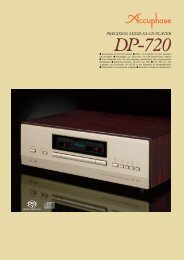
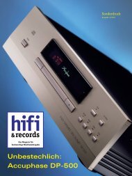
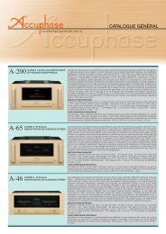
<strong>AAVA</strong> operation principle<br />
The music signal is converted into 16 types<br />
of weighted current by V-I (voltage - current)<br />
converting amplifi ers [1/2, 1/2 2 , ... 1/2 15 , 1/2 16 ].<br />
The 16 currents are turned on or off by 16 current<br />
switches, and the combination of switch<br />
settings determines the overall <strong>volume</strong>. The<br />
switching operation is <strong>control</strong>led by a CPU according<br />
to the position of the <strong>volume</strong> <strong>control</strong><br />
knob. The combined signal current forms a<br />
variable gain circuit that adjusts the <strong>volume</strong>.<br />
Finally, the combined current is converted<br />
back into a voltage by an I-V<br />
(current - voltage) converter.<br />
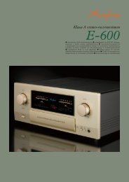
n <strong>AAVA</strong> <strong>volume</strong> <strong>control</strong> assembly<br />
with higher integration density<br />
of components and circuitry.<br />
INPUT<br />
Buffer<br />
5-MCS<br />
Input music signal<br />
n <strong>AAVA</strong> means analog processing<br />
The <strong>AAVA</strong> circuit converts the music signal from a voltage into a current, switches<br />
gain by means of current switches, and then reconverts the current into a voltage.<br />
The entire process is carried out in the analog domain.<br />
n Same operation feel as a conventional high-quality <strong>volume</strong> <strong>control</strong><br />
The <strong>volume</strong> <strong>control</strong> knob position is detected by a dedicated CPU which in turn<br />
selects the current switches for <strong>AAVA</strong> operation. Operating the knob therefore<br />
feels exactly the same as with a conventional <strong>control</strong>, and as before, operation<br />
via the remote commander is also possible.<br />
n Attenuator and balance <strong>control</strong> also implemented by <strong>AAVA</strong><br />
The functions of the attenuator and the left/right balance <strong>control</strong> are covered<br />
by the <strong>AAVA</strong> circuit as well, eliminating the need for additional circuit <strong>stage</strong>s.<br />
Keeping the confi guration simple helps to maintain high performance and<br />
sonic purity.<br />
n Display shows <strong>volume</strong> level as numeric value<br />
The <strong>volume</strong> level (degree of attenuation) as set with <strong>AAVA</strong> is shown as a numeric<br />
indication in the center of the front panel. The indication ranges from MAX (0 dB)<br />
to MIN (lowest setting).<br />
Conversion into current with 16<br />
weighting <strong>stage</strong>s (1/2 - 1/216 V-I Converter<br />
)<br />
16 current switches<br />
(65,536 possible combinations)<br />
CPU<br />
Volume<br />
Balance<br />
Attenuator<br />
CPU detects position of <strong>volume</strong> knob and operates<br />
current on/off switches according to knob position<br />
<strong>AAVA</strong> confi guration in E-560<br />
Current values<br />
are added<br />
I-V Converter<br />
Reconversion of<br />
current into voltage<br />
OUTPUT<br />
Volume knob is turned<br />
and position is detected<br />
n CPU assembly which <strong>control</strong>s <strong>AAVA</strong> and various other<br />
functions.
n Power amplifi er assembly and output<br />
<strong>stage</strong> with triple parallel push-pull power<br />
MOS-FETs directly mounted to large heat sink.<br />
n Power MOS FETs in triple parallel<br />
confi guration operating in pure<br />
class A deliver guaranteed linear<br />
power: 120 watts/channel into 2<br />
ohms, 60 watts/channel into 4 ohms<br />
or 30 watts/channel into 8 ohms.<br />
n Instrumentation amplifi er principle<br />
in power amplifi er section allows<br />
fully balanced signal paths. Current<br />
feedback design ensures outstanding high-range phase characteristics,<br />
together with further improved MCS+ topology.<br />
n Tone <strong>control</strong>s using active fi lters for optimum sound quality.<br />
n Dedicated headphone amplifi er optimized<br />
for sound quality.<br />
n Loudness compensator for enhanced bass<br />
at low listening levels.<br />
n Versatile array of inputs with two balanced inputs<br />
to shut out external noise interference.<br />
n Logic-<strong>control</strong>led relays assure high sound<br />
quality and long-term reliability.<br />
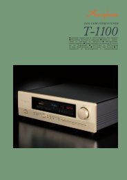
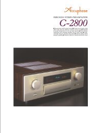
Gold-plated input/output jacks connected directly to relays<br />
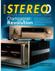
+ INPUT<br />
GAIN CONTROL<br />
CIRCUIT<br />
- INPUT<br />
NFB<br />
NETWORK<br />
NFB<br />
NETWORK<br />
Power MOS-FETs<br />
MCS+<br />
Multiple Circuit<br />
Summing-up<br />
Bias<br />
stabilizer<br />
Bias<br />
stabilizer<br />
Bias<br />
stabilizer<br />
Bias<br />
stabilizer<br />
n Power supply with massive higheffi<br />
ciency toroidal transformer and<br />
large fi ltering capacitors provides<br />
ample reserves.<br />
n Individual phase setting supported<br />
for each input position.<br />
n Analog peak power meters for<br />
monitoring output levels.<br />
n Two sets of large-size speaker<br />
terminals accept also Y lugs.<br />
n Two option board installation<br />
slots provide further versatility.<br />
With AD-20 board, MC/MM<br />
switching on E-560 front panel is<br />
possible.<br />
n EXT PRE switch and power<br />
amplifi er input connectors allow<br />
independent use of power amplifi<br />
er section.<br />
Bias<br />
stabilizer<br />
REGULATOR<br />
REGULATOR<br />
n Supplied remote commander<br />
RC-200<br />
Allows <strong>volume</strong> adjustment<br />
and input<br />
source switching.<br />
OUTPUT<br />
Circuit diagram of E-560 power amplifi er (one channel)<br />
Toroidal power transformer Filtering capacitors<br />
Large speaker terminals
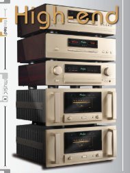
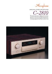
Connection Example For Bi-amping Setup<br />
In a bi-amped setup, the speaker units for the LOW frequency<br />
range and HIGH frequency range are driven by separate<br />
amplifi ers of equal gain, for even better sound quality.<br />
The speakers must<br />
have a built-in crossover<br />
network and separate<br />
inputs for LOW and<br />
HIGH range.<br />
The example shows a<br />
setup with an additional<br />
amplifi er for the high<br />
frequency range.<br />
E-560<br />
Response in dB<br />
Analog<br />
output<br />
n Rear Panel<br />
Option board<br />
installation slots<br />
Left loudspeaker Right loudspeaker<br />
CD player Power amplifi er (A-35 or similar)<br />
n Front Panel<br />
From PRE OUT<br />
LOW HIGH LOW HIGH<br />
To INPUT<br />
J Attenuator button<br />
K Headphone jack<br />
L Line inputs (unbalanced)<br />
TUNER CD LINE 1, 2, 3<br />
M Recorder inputs and outputs<br />
N Preamplifi er outputs<br />
O Power amplifi er inputs<br />
P Left/right speaker output terminals A/B<br />
Q CD/LINE inputs (balanced)<br />
Ground Inverted (–)<br />
Non-inverted (+)<br />
R AC power connector A Input selector<br />
B Function indicator LEDs<br />
C Volume <strong>control</strong><br />
D Power switch<br />
E Function buttons (A)<br />
Speaker selector (A/B/OFF), Phase selector,<br />
Recording selector (ON/PLAY),<br />
Preamplifi er/power amplifi er separator (EXT PRE)<br />
F Bass <strong>control</strong><br />
G Treble <strong>control</strong><br />
H Balance <strong>control</strong><br />
I Function buttons (B)<br />
Tone <strong>control</strong> (ON/OFF), Meter operation (ON/OFF),<br />
MONO/STEREO selector, Volume level display (ON/OFF),<br />
Loudness compensator, MC/MM selector<br />
Option Boards<br />
Three types of option boards can be used in the E-560:<br />
the Digital Input Board DAC-20, Analog Disc Input Board<br />
AD-20, and Line Input Board LINE-10. These boards can<br />
be installed in the rear-panel slots as required.<br />
m It is possible to install two identical boards.<br />
m The Analog Disc Input Board AD-9/AD-10 and the Line Input<br />
Board LINE-9 can also be used.<br />
m When using the AD-9/AD-10, the MC/MM button of the<br />
E-560 has no effect. MC/MM switching must be performed<br />
on the board.<br />
Pressing this button<br />
opens the sub panel.<br />
Photo shows an example for<br />
option board installation.<br />
Remarks<br />
This product is available in versions for 120/230 V AC. Make sure that the voltage shown on the rear panel matches the AC line voltage in your area.<br />
The shape of the AC inlet and plug of the supplied power cord depends on the voltage rating and destination country.<br />
n Supplied accessories:<br />
m AC power cord<br />
m Remote Commander RC-200<br />
<br />
Digital Input Board DAC-20<br />
This board features an MDS (Multiple Delta<br />
Sigma) ++ type D/A converter and allows<br />
direct digital connection of a CD player, MD or<br />
other component with digital output (sampling<br />
frequency up to 96 kHz, 24 bits), for high-quality<br />
music reproduction.<br />
m Inputs for coaxial and optical fi ber connections are provided.<br />
Analog Disc Input Board AD-20<br />
This board serves for playback of analog records.<br />
It contains a high-performance, high-gain phono<br />
equalizer.<br />
m MC/MM switching is possible on the front panel of the<br />
E-560.<br />
m Internal DIP switches <strong>control</strong> MC input impedance and<br />
subsonic fi lter on/off.<br />
Gain : 62 dB<br />
MC Input impedance : 10/30/100 ohms (selectable)<br />
MM<br />
Gain : 36 dB<br />
Input impedance : 47 kilohms<br />
Line Input Board LINE-10<br />
This option board provides an additional set of<br />
unbalanced line inputs.<br />
Guaranteed Specifi cations<br />
[based on the EIA RS-490 test standard]<br />
m Rated Continuous Average <strong>Output</strong> Power (both channels operating simultaneously at 20 - 20,000 Hz)<br />
150 W/ch 1-ohm load ()<br />
120 W/ch 2-ohm load<br />
60 W/ch 4-ohm load<br />
30 W/ch 8-ohm load<br />
() These loads are for music signals only.<br />
m Total Harmonic Distortion (both channels operating simultaneously at 20 - 20,000 Hz)<br />
0.05% 2-ohm load<br />
0.03% 4 to 16 ohm load<br />
m IM Distortion 0.01% or less<br />
m Frequency Characteristics HIGH LEVEL INPUT/POWER IN<br />
20 - 20,000 Hz +0, –0.2 dB (for rated continuous average output)<br />
3 - 150,000 Hz +0, –3.0 dB (for 1 watt output)<br />
m Damping Factor 200 (with 8-ohm load, 50 Hz)<br />
m Input Sensitivity, Input Impedance<br />
Input<br />
Sensitivity<br />
Input<br />
For rated output For 1 W output (EIA) impedance<br />
HIGH LEVEL INPUT 77.7 mV 14.2 mV 20 kΩ<br />
BALANCED INPUT 77.7 mV 14.2 mV 40 kΩ<br />
POWER IN 0.617 V 113 mV 20 kΩ<br />
m <strong>Output</strong> Voltage, <strong>Output</strong> Impedance<br />
PRE OUTPUT: 0.617 V, 50-ohm<br />
(at rated continuous average output)<br />
m Gain HIGH LEVEL INPUT → PRE OUTPUT: 18 dB<br />
POWER IN → OUTPUT: 28 dB<br />
m Tone Controls Turnover frequency and adjustment range<br />
BASS: 300 Hz ±10 dB (50 Hz)<br />
TREBLE: 3 kHz ±10 dB (20 kHz)<br />
m Loudness Compensation +6 dB (100 Hz)<br />
m Attenuator<br />
m Signal-to-Noise Ratio<br />
–20 dB<br />
Input<br />
Input shorted (A weighting)<br />
S/N ratio at rated output<br />
EIA S/N<br />
HIGH LEVEL INPUT 98 dB 93 dB<br />
BALANCED INPUT 93 dB 93 dB<br />
POWER IN 116 dB 98 dB<br />
m Power Level Meters Logarithmic compression, peak reading meters<br />
<strong>Output</strong> dB/% scale<br />
m Load Impedance 2 - 16 ohms<br />
m Stereo Headphones Suitable impedance: 8 - 100 ohms<br />
m Power Source AC 120 V/230 V 50/60 Hz<br />
(Voltage as indicated on rear panel)<br />
m Power Consumption 170 watts idle<br />
270 watts in accordance with IEC 60065<br />
m Maximum Dimensions Width 465 mm (18-5/16”)<br />
Height 191 mm (7-1/2”)<br />
Depth 426 mm (16-3/4”)<br />
m Mass 24.0 kg (52.9 lbs) net<br />
30.0 kg (66.1 lbs) in shipping carton<br />
m Specifi cations and design subject to change without notice for improvements. http://www.accuphase.com K0905Y PRINTED IN JAPAN 851-0188-00 (B1)