MasteringPhysics: Assignment Print View
MasteringPhysics: Assignment Print View
MasteringPhysics: Assignment Print View

You also want an ePaper? Increase the reach of your titles
YUMPU automatically turns print PDFs into web optimized ePapers that Google loves.
<strong>MasteringPhysics</strong>: <strong>Assignment</strong> <strong>Print</strong> <strong>View</strong> http://session.masteringphysics.com/myct/assignment<strong>Print</strong>?assig...<br />
[ <strong>Assignment</strong> <strong>View</strong> ]<br />
Eðlisfræði 2, vor 2007<br />
25. Current, Resistance, and Electromagnetic Force<br />
<strong>Assignment</strong> is due at 2:00am on Wednesday, February 14, 2007<br />
Credit for problems submitted late will decrease to 0% after the deadline has passed.<br />
The wrong answer penalty is 2% per part. Multiple choice questions are penalized as described in the online help.<br />
The unopened hint bonus is 2% per part.<br />
You are allowed 4 attempts per answer.<br />
Current as Charge Flow<br />
Electricity and Water Analogy<br />
Learning Goal: To understand the analogy between water pressure, water flow, voltage, and current<br />
As suggested by the fact that we call both currents, the flow of charged particles through an electrical circuit is<br />
analogous in some ways to the flow of water through a pipe.<br />
When water flows from a small pipe to a large pipe, the flow (measured, for instance, in gallons per minute) is the<br />
same in both pipes, because the amount of water entering one pipe must equal the amount leaving the other. If not,<br />
water would accumulate in the pipes. For the same reason, the total electric current is constant for circuit<br />
elements in series.<br />
Water pressure is analogous to total electric potential (voltage), and a pump is analogous to a battery. Water<br />
flowing through pipes loses pressure, just as current flowing through a resistor falls to lower voltage. A pump<br />
uses mechanical work to raise the water's pressure and thus its potential energy; in a battery, chemical reactions<br />
cause charges to flow against the average local electric field, from low to high voltage, increasing their potential<br />
energy.<br />
Part A<br />
Consider the following water circuit: water is continually pumped to high<br />
pressure by a pump, and then funnelled into a pipe that has lower pressure at<br />
its far end (else the water would not flow through the pipe) and back to the<br />
pump. Two such circuits are identical, except for one difference: the pipes in<br />
one circuit have a larger diameter than the pipes in the other circuit. Through<br />
which circuit is the flow of water greater?<br />
ANSWER: Answer not displayed<br />
Part B<br />
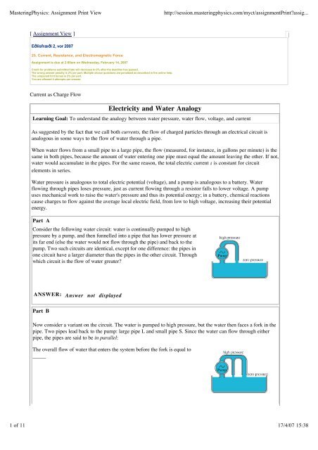
Now consider a variant on the circuit. The water is pumped to high pressure, but the water then faces a fork in the<br />
pipe. Two pipes lead back to the pump: large pipe L and small pipe S. Since the water can flow through either<br />
pipe, the pipes are said to be in parallel:<br />
The overall flow of water that enters the system before the fork is equal to<br />
_____<br />
1 of 11 17/4/07 15:38<br />
[
<strong>MasteringPhysics</strong>: <strong>Assignment</strong> <strong>Print</strong> <strong>View</strong> http://session.masteringphysics.com/myct/assignment<strong>Print</strong>?assig...<br />
Hint B.1 Water conservation<br />
ANSWER: Answer not displayed<br />
Part C<br />
Part D<br />
Hint not displayed<br />
Part not displayed<br />
Consider a new circuit: water is pumped to high pressure and fed into only one pipe. The pipe has two distinct<br />
segments of different diameters; the second half of the pipe has a smaller diameter than the first half:<br />
Which of the following statements about the flow and change in pressure<br />
through each segment is true?<br />
ANSWER: Answer not displayed<br />
Capacitor Supplies Current to Bulb<br />
A large capacitor is charged with on one electrode and on the other. At time , the capacitor is connected in<br />
series to two ammeters and a bulb. The ammeter connected to the positive side of the capacitor reads , and the<br />
ammeter connected to the negative side of the capacitor reads .<br />
Both ammeters will read positive if current flows in a clockwise sense through<br />
the circuit (from the + to the - terminal of the meter).<br />
Part A<br />
Immediately after time , what happens to the charge on the capacitor plates?<br />
a. Electrons flow through the circuit from the positive to the negative side of the capacitor.<br />
b. Electrons flow through the circuit from the negative to the positive side of the capacitor.<br />
c. The positive and negative charges attract each other, so they stay in the capacitor.<br />
d. Current flows clockwise through the circuit.<br />
e. Current flows counterclockwise through the circuit.<br />
Hint A.1 What is meant by current flow?<br />
Hint not displayed<br />
List the letters corresponding to the correct statements in alphabetical order. Do not use<br />
commas. For instance, if you think that only statements a and c are correct, write ac.<br />
2 of 11 17/4/07 15:38
<strong>MasteringPhysics</strong>: <strong>Assignment</strong> <strong>Print</strong> <strong>View</strong> http://session.masteringphysics.com/myct/assignment<strong>Print</strong>?assig...<br />
Part B<br />
At any given instant after , what is the relationship between the current flowing through the two ammeters,<br />
and , and the current through the bulb, ?<br />
ANSWER:<br />
This is a fundamental result that reflects conservation of charge. In a circuit where elements are arranged in<br />
series, the voltage changes as current flows through the circuit, but the current is constant. Otherwise, charge<br />
would accumulate in the circuit.<br />
In a circuit where elements are arranged in parallel, the opposite is true; all parallel branches have the same<br />
voltage, although the current may be different in different branches. This result is formalized in Kirchoff's<br />
junction law -- the algebraic sum of currents entering any junction must be zero. (In this law, a current leaving<br />
a junction is considered negative).<br />
Part C<br />
What is the sign of the quantity ?<br />
ANSWER: Positive Negative<br />
Part D<br />
Light bulbs are often assumed to obey Ohm's law, but this is not strictly true, because their resistance increases as<br />
the filament heats up at higher voltages. A typical flashlight bulb at full brilliance draws a current of<br />
approximately 0.5 while attached to a 3 source. For this problem, assume that the changing resistance causes<br />
the current to be 0.5 for any voltage between 2 and 3 .<br />
Suppose this flashlight bulb is attached to a capacitor as shown in the circuit from the problem introduction. If<br />
the capacitor has a capacitance of 3 (an unusually large but not unrealistic value) and is initially charged to 3 ,<br />
how long will it take for the voltage across the flashlight bulb to drop to 2 (where the bulb will be orange and<br />
dim)? Call this time .<br />
Hint D.1 How to approach this problem<br />
Part D.2 Initial charge on capacitor<br />
Part D.3 Charge on capacitor at 2 V<br />
Hint not displayed<br />
Part not displayed<br />
Part not displayed<br />
Hint D.4 Relationship between charge and current<br />
Hint not displayed<br />
Express numerically, in seconds, to the nearest integer.<br />
ANSWER: = 6 seconds<br />
3 of 11 17/4/07 15:38
<strong>MasteringPhysics</strong>: <strong>Assignment</strong> <strong>Print</strong> <strong>View</strong> http://session.masteringphysics.com/myct/assignment<strong>Print</strong>?assig...<br />
Ohm's Law and Resistance<br />
Resistance from Microscopic Ohm's law<br />
Your task is to calculate the resistance of a simple cylindrical resistor with wires connected to the ends, such as the<br />
carbon composition resistors that are used on electronic circuit boards. Imagine that the resistor is made by<br />
squirting material whose conductivity is into a cylindrical mold with length and cross-sectional area . Assume<br />
that this material satisfies Ohm's law. (It should if the resistor is operated<br />
within its power dissipation limits.)<br />
Part A<br />
What is the resistance of this resistor?<br />
Hint A.1 General approach<br />
Part A.2 Microscopic Ohm's law<br />
Hint not displayed<br />
Part not displayed<br />
Part A.3 Find the voltage from the electric field<br />
Part not displayed<br />
Part A.4 Find the current from the current density<br />
Hint A.5 Ohm's law for the resistor<br />
Part not displayed<br />
Hint not displayed<br />
Express the resistance in terms of variables given in the introduction. Do not use or in<br />
your answer.<br />
ANSWER: = Answer not displayed<br />
Electrical Safety<br />
Most of us have experienced an electrical shock one way or another in our lives. Most electrical shocks we receive<br />
are minor ones from wooly sweaters or from shoes. However, some shocks, especially from outlets or power<br />
mains, can be fatal. This question will show you how to estimate the current through a human body when subject<br />
to an electrical shock.<br />
Imagine a situation in which a person accidentally touches an electrical socket with both hands. By modeling the<br />
arm and the chest to be a cylindrical tube with a total length , cross-sectional area , and resistivity<br />
, you can calculate the current in amperes through the person when a potential difference of is<br />
applied across the two hands. Assume that the current flows only through the modeled cylindrical tube.<br />
Part A<br />
What is the current flow through the body?<br />
Hint A.1 Calculating the resistance<br />
4 of 11 17/4/07 15:38
<strong>MasteringPhysics</strong>: <strong>Assignment</strong> <strong>Print</strong> <strong>View</strong> http://session.masteringphysics.com/myct/assignment<strong>Print</strong>?assig...<br />
Part A.2 Obtaining the expression for current<br />
Hint not displayed<br />
Part not displayed<br />
Express your answer numerically to two significant figures.<br />
ANSWER: = 0.037 A<br />
The following are the effects of current on humans:<br />
1 mA = A or less: barely noticeable;<br />
1 to 8 mA: strong surprise;<br />
8 to 15 mA: unpleasant, victims able to detach from source;<br />
15 to 75mA: painful, dangerous;<br />
75 mA or more: fatal.<br />
These values vary according to sex, age, and weight.<br />
Resistance of a Heater<br />
A 1500-W heater is designed to be plugged into a 120-V outlet.<br />
Part A<br />
What current will flow through the heating coil when the heater is plugged in?<br />
Hint A.1 Setting it up<br />
Part A.2 Power<br />
Part A.3 Finishing up<br />
Hint not displayed<br />
Part not displayed<br />
Part not displayed<br />
Express your answer for the current numerically, to three significant figures.<br />
ANSWER: = 12.5 A<br />
Note that watts/volts has the correct units: Since<br />
and<br />
then<br />
Part B<br />
What is , the resistance of the heater?<br />
Hint B.1 Which equation to use<br />
Hint not displayed<br />
5 of 11 17/4/07 15:38<br />
,<br />
.
<strong>MasteringPhysics</strong>: <strong>Assignment</strong> <strong>Print</strong> <strong>View</strong> http://session.masteringphysics.com/myct/assignment<strong>Print</strong>?assig...<br />
Express your answer numerically, to three significant figures.<br />
ANSWER: = 9.6 ohms<br />
Part C<br />
How long does it take to raise the temperature of the air in a good-sized living room by ?<br />
Note that the heat capacity of air is 1006 and the density of air is .<br />
Part C.1 Mass of the air<br />
Part C.2 How many joules<br />
Part not displayed<br />
Part not displayed<br />
Express your answer numerically in minutes, to three significant figures.<br />
ANSWER: = 16.1 minutes<br />
Actually, the heat capacity of the walls and other material in the room will generally exceed that of the air by<br />
several times, so an hour is a more reasonable time to heat the room by this much.<br />
Current and Current Density at a Junction<br />
Consider the juncion of three wires as shown in the diagram.<br />
The magnitudes of the current density and the diameters for wires 1 and 2 are given in the table. The current<br />
directions are indicated by the arrows.<br />
Wire<br />
Current density<br />
( )<br />
1 3.0 2.0<br />
2 5.0 3.0<br />
Part A<br />
Find the current in wire 3.<br />
Diameter<br />
( )<br />
Hint A.1 How to approach the problem<br />
Find the total current through wires 1 and 2. Then use the Kirchhoff's junction rule to determine the current<br />
through wire 3.<br />
Hint A.2 Kirchhoff's rule<br />
Recall that Kirchhoff's junction rule is merely another way of stating the conservation of charge over time<br />
(charge flowing into a junction must equal charge flowing out). Otherwise, there would be an infinite buildup of<br />
charge over time. Therefore, the current entering a junction is equal to the current leaving a junction.<br />
6 of 11 17/4/07 15:38
<strong>MasteringPhysics</strong>: <strong>Assignment</strong> <strong>Print</strong> <strong>View</strong> http://session.masteringphysics.com/myct/assignment<strong>Print</strong>?assig...<br />
Hint A.3 Current density and current<br />
Recall that current density is just the total current divided by the cross-sectional area of the wire. That is, .<br />
Hint A.4 Area of the wire<br />
The wire cross-section is circular, so the area is just , where is the radius of the wire.<br />
Express your answer in amperes to two significant figures. Call current out of the junction<br />
positive and current into the junction negative.<br />
ANSWER: = -26<br />
Part B<br />
Find the magnitude of the current density in wire 3. The diameter of wire 3 is 1.5 millimeters.<br />
Hint B.1 Current density and current<br />
Hint B.2 Area of the wire<br />
Hint not displayed<br />
Hint not displayed<br />
Express your answer in amperes per square millimeter to two significant figures.<br />
ANSWER: = 15 .<br />
How a Real Voltmeter Works<br />
Unlike the idealized voltmeter, a real voltmeter has a resistance that is not infinitely large.<br />
Part A<br />
A voltmeter with resistance is connected across the terminals of a battery of emf and internal resistance .<br />
Find the potential difference measured by the voltmeter.<br />
Hint A.1 How to approach the problem<br />
Hint not displayed<br />
Hint A.2 How to find the potential between points a and b<br />
Hint A.3 An expression for<br />
Hint A.4 Using Kirchhoff's loop rule<br />
ANSWER: =<br />
Hint not displayed<br />
Hint not displayed<br />
Hint not displayed<br />
With a little algebraic manipulation, the answer can also be written as<br />
In this form it is easier to see why the voltmeter reading differs from the actual emf it is supposed to measure<br />
by only a small amount if . It is a good idea to check that the answer gives the correct result in the limit<br />
that .<br />
7 of 11 17/4/07 15:38<br />
.
<strong>MasteringPhysics</strong>: <strong>Assignment</strong> <strong>Print</strong> <strong>View</strong> http://session.masteringphysics.com/myct/assignment<strong>Print</strong>?assig...<br />
Part B<br />
If = and , find the minimum value of the voltmeter resistance for which the voltmeter reading is<br />
within 1.0% of the emf of the battery.<br />
Hint B.1 What is meant by "within 1.0%"<br />
Examine the expression for the potential difference measured by the voltmeter:<br />
From this expression, you can see that the difference between the potential difference measured by the voltmeter<br />
and the actual emf of the battery is<br />
In our case, the specifications require that this expression be less than 1%.<br />
Express your answer numerically (in ohms) to at least three significant digits.<br />
ANSWER: = 44.6<br />
Typical voltmeters have a range of possible resistances, some of which are much larger than the value you just<br />
obtained (on the order of megaohms). This allows reasonably accurate measurements of much larger resistances<br />
to be made.<br />
Measuring the EMF and Internal Resistance of a Battery<br />
When switch S in the figure is open, the voltmeter V of the battery reads 3.05 . When the switch is closed, the<br />
voltmeter reading drops to 2.91 , and the ammeter A reads 1.65 . Assume that the two meters are ideal, so they<br />
do not affect the circuit.<br />
Part A<br />
Find the emf .<br />
Express your answer in volts to three significant digits.<br />
ANSWER: = 3.05<br />
Part B<br />
Find the internal resistance of the battery.<br />
Hint B.1 How to approach the problem<br />
Hint not displayed<br />
Express your answer in ohms to four significant digits.<br />
ANSWER: = 8.485×10 -2<br />
8 of 11 17/4/07 15:38<br />
.
<strong>MasteringPhysics</strong>: <strong>Assignment</strong> <strong>Print</strong> <strong>View</strong> http://session.masteringphysics.com/myct/assignment<strong>Print</strong>?assig...<br />
Part C<br />
Find the circuit resistance .<br />
Part C.1 Find the voltage drop across the circuit resistor<br />
Part not displayed<br />
Express your answer in ohms to three significant digits.<br />
ANSWER: = 1.76<br />
This is the kind of circuit you would use in real life to measure the emf and internal resistance of a battery.<br />
You need the second resistor to increase the resistance in the circuit so that the current flowing through the<br />
ammeter is not too large. In fact, you would need to figure out roughly how big a resistance to use once you<br />
had determined the emf of the battery, depending on the range of the ammeter you were using.<br />
Power in Resistive Circuits<br />
Power in DC Circuits<br />
A battery does work in moving charge around a circuit i.e. sustaining a current through the circuit. To illustrate<br />
this point, consider a resistor with a voltage across it and a current flowing through it.<br />
Part A<br />
Focus on a single charge, , passing through the resistor. Find the work done on the charge by the electric field<br />
in the resistor.<br />
Hint A.1 How to approach this problem<br />
Hint A.2 Formula for work<br />
Part A.3 Find the force on the charge<br />
Hint not displayed<br />
Hint not displayed<br />
Part not displayed<br />
Express the work done on the charge in terms of , , and/or .<br />
ANSWER: = Answer not displayed<br />
Part B<br />
Part not displayed<br />
Power Delivered to a Resistor<br />
In this problem you will derive two different formulas for the power delivered to a resistor.<br />
Part A<br />
What is the power supplied to a resistor whose resistance is when it is known that it has a voltage across<br />
it?<br />
Part A.1 Find an expression for power<br />
Part not displayed<br />
Part A.2 Find current in terms of voltage and resistance<br />
Part not displayed<br />
9 of 11 17/4/07 15:38
<strong>MasteringPhysics</strong>: <strong>Assignment</strong> <strong>Print</strong> <strong>View</strong> http://session.masteringphysics.com/myct/assignment<strong>Print</strong>?assig...<br />
Express the power in terms of and .<br />
ANSWER: = Answer not displayed<br />
Part B<br />
Part not displayed<br />
Power in Resistive Electric Circuits<br />
Learning Goal: To understand how to compute power dissipation in a resistive circuit.<br />
The circuit in the diagram consists of a battery with EMF , a resistor with<br />
resistance , an ammeter, and a voltmeter. The voltmeter and the ammeter<br />
(labeled V and A) can be considered ideal; that is, their resistances are infinity<br />
and zero, respectively. The current in the resistor is , and the voltage across it<br />
is . The internal resistance of the battery is not zero.<br />
Part A<br />
What is the ammeter reading ?<br />
Express your answer in terms of , , and .<br />
ANSWER: =<br />
Note that the resistances of the ammeter and voltmeter do not appear in the answer. That is because these two<br />
circuit elements are "ideal." The voltmeter has infinite resistance, so no current flows through it (imagine that<br />
there is a short circuit inside the voltmeter). The ammeter has zero resistance, so there is no voltage drop as<br />
current flows through it.<br />
Part B<br />
What is the voltmeter reading ?<br />
Part B.1 Potential difference across the internal resistance<br />
Express your answer in terms of , , and .<br />
ANSWER: =<br />
Part not displayed<br />
In the following parts, you will express the power dissipated in the resistor of resistance using three different<br />
sets of variables.<br />
Part C<br />
What is the power dissipated in the resistor?<br />
Express your answer in terms of and .<br />
ANSWER: =<br />
Part D<br />
10 of 11 17/4/07 15:38
<strong>MasteringPhysics</strong>: <strong>Assignment</strong> <strong>Print</strong> <strong>View</strong> http://session.masteringphysics.com/myct/assignment<strong>Print</strong>?assig...<br />
Again, what is the power dissipated in the resistor?<br />
This time, express your answer in terms of one or more of the following variables: , ,<br />
and .<br />
ANSWER: =<br />
Part E<br />
For the third time, what is the power dissipated in the resistor?<br />
Express your answer in terms of one or more of the following variables: , , and .<br />
ANSWER: =<br />
Part F<br />
What is the power dissipated in the entire circuit?<br />
Hint F.1 How to approach the problem<br />
The total power dissapated in the circuit is the algebraic sum of the power dissipated in all the elements of the<br />
circuit. You have already found the power dissipated in the resistor. Now consider the other circuit elements.<br />
Part F.2 Find the power dissipated in the battery<br />
How much power is dissipated in the battery?<br />
Hint F.2.a How can power be dissipated inside a battery?<br />
Hint not displayed<br />
Express your answer in terms of one or more of the following variables: , , and .<br />
ANSWER: =<br />
Part F.3 Find the power dissipated between points 1 and 2<br />
What is the power dissipated in the part of the circuit between points 1 and 2?<br />
ANSWER:<br />
Express your answer in terms of one or more of the following variables: , , and .<br />
ANSWER: =<br />
Part G<br />
What is the total power dissipated in the entire circuit, in terms of the EMF of the battery and the current in<br />
the circuit?<br />
Express your answer in terms of and the ammeter current .<br />
ANSWER: =<br />
Summary 7 of 11 problems complete (62.24% avg. score)<br />
34.23 of 35 points<br />
11 of 11 17/4/07 15:38