TREATMENT - Environmental Protection Agency
TREATMENT - Environmental Protection Agency
TREATMENT - Environmental Protection Agency

Create successful ePaper yourself
Turn your PDF publications into a flip-book with our unique Google optimized e-Paper software.
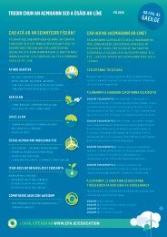
ENVIRONMENTAL PROTECTION AGENCY An Ghniomhaireacht urn Chaornhnü Comhshac<br />
WASTE WATER<br />
<strong>TREATMENT</strong><br />
NL4NUALS<br />
PRIMARY,<br />
SECONDARY ANL<br />
TERTIARY<br />
<strong>TREATMENT</strong><br />
document<br />
contains '3t pages
WASTE WATER <strong>TREATMENT</strong><br />
MANUALS<br />
PRIMARY, SECONDARY and<br />
TERTIARY <strong>TREATMENT</strong><br />
<strong>Environmental</strong> <strong>Protection</strong> <strong>Agency</strong><br />
Ardcavan, Wexford, Ireland.<br />
Telephone: +353-53-47120 Fax: +353-53-47119
© <strong>Environmental</strong> <strong>Protection</strong> <strong>Agency</strong> 1997<br />
Parts of this publication may be reproduced without further permission, provided the<br />
source is acknowledged.<br />
ISBN 1 899965 46 7<br />
WASTE WATER <strong>TREATMENT</strong> MANUALS<br />
PRIMARY, SECONDARY and TERTIARY <strong>TREATMENT</strong><br />
Published by the <strong>Environmental</strong> <strong>Protection</strong> <strong>Agency</strong>, Ireland.<br />
Price Ir15 1/97/400
TABLE OF CONTENTS<br />
CONTENTS i<br />
ACKNOWLEDGEMENTS viii<br />
PREFACE ix<br />
ABBREVIATIONS x<br />
1. <strong>TREATMENT</strong> OF WASTE WATER 1<br />
1.1 <strong>TREATMENT</strong> OF WASTE WATER 1<br />
1.2 LEGISLATION 1<br />
1.3 OVERVIEW OF WASTE WATER <strong>TREATMENT</strong> 2<br />
1.4 ROLE OF THE PLANT OPERATOR 2<br />
2. GENERAL CONSIDERATIONS FOR THE <strong>TREATMENT</strong><br />
OF WASTE WATER<br />
2.1 CHARACTERISTICS OF URBAN WASTE WATER 5<br />
2.2 PARAMETERS BY WHICH WASTE WATER IS MEASURED 5<br />
2.3 LABORATORY ACCREDITATION 7<br />
2.4 PLANT LOADING 7<br />
2.4.1 HYDRAULIC LOADING 8<br />
2.4.2 ORGANIC LOADING 8<br />
2.4.3 RETURN SLUDGE LIQUORS 9<br />
2.5 INSTRUMENTATION 9<br />
2.6 TELEMETRY 10<br />
2.7 SCADA SYSTEMS 10<br />
2.8 INSTRUMENTATION AND CONTROL SYSTEMS 10<br />
3. BIOLOGICAL <strong>TREATMENT</strong> OF WASTE WATERS 13<br />
3.1 WASTE WATER FLORA AND FAUNA 13<br />
3.2 BACTERIAL GROWTH 14<br />
3.3 INHIBITION 16<br />
4. PRIMARY <strong>TREATMENT</strong> OF WASTE WATER 19<br />
4.1 PROCESS DESCRIPTION 19<br />
4.2 PRIMARY SETTLEMENT TANKS 19<br />
4.3 SEPTIC TANKS AND IMHOFF TANKS 20
ii <strong>TREATMENT</strong> OF WASTE WATER<br />
4.4 TUBE AND LAMELLA SETTLERS 22<br />
4.5 DISSOLVED AIR FLOTATION 22<br />
5. ACTIVATED SLUDGE (SUSPENDED GROWTH) PROCESSES 23<br />
5.1 PROCESS DESCRIPTION 23<br />
5.2 MIXED LIQUOR SUSPENDED SOLIDS 24<br />
5.3 OXYGEN REQUIREMENTS AND TRANSFER 24<br />
5.3.1 THEORY 24<br />
5.3.2 TYPES OF EQUIPMENT<br />
25<br />
5.3.3 TRANSFER EFFICIENCY 26<br />
5.3.4 PRACTICAL APPLICATION 27<br />
5.4 CLARIFICATION OF MIXED LIQUOR<br />
5.5 SLUDGE SETTLEABILITY 28<br />
5.6 RETURN ACTIVATED SLUDGE (RAS) 29<br />
5.7 WASTE ACTIVATED SLUDGE (WAS)<br />
5.8 PROCESS CONTROL IN THE ACTIVATED SLUDGE SYSTEM 30<br />
5.9 SOLIDS LOADING RATE (FIM RATIO)<br />
5.10 SLUDGE AGE 31<br />
5.11 COMPARISON BETWEEN FIM RATIO AND SLUDGE AGE 31<br />
5.12 ADVANTAGES OF HIGH AND LOW FIM RATIOS 31<br />
5.13 PROCESS VARIATIONS IN ACTIVATED SLUDGE 33<br />
5.13.1 CONVENTIONAL AERATION 33<br />
5.13.2 EXTENDED AERATION 34<br />
5.13.3 HIGH RATE ACTIVATED SLUDGE 34<br />
5.14 PROCESS CONFIGURATIONS IN ACTIVATED SLUDGE 35<br />
5.14.1 COMPLETELY MIXED 35<br />
5.14.2 PLUG FLOW 35<br />
5.14.3 TAPERED AERATION 36<br />
5.14.4 STEP FEEDING . 36<br />
5.14.5 SLUDGE RE-AERATION 36<br />
5.14.6 OXIDA1ION DITCH 36<br />
5.14.7 SEQUENCING BATCH REACTORS 37<br />
5.14.8 HIGH INTENSITY SYSTEMS 37<br />
5.15 NUISANCE 39<br />
5.16 FOAMING 39<br />
5.17 SOLIDS WASHOUT 41<br />
5.18 SLUDGE TYPES 41<br />
5.18.1 RISING SLUDGE 41<br />
28<br />
30<br />
30
CONTENTS iii<br />
5.18.2ASHING 42<br />
5.18.3 PIN-POINT FLOC 42<br />
5.18.4 FILAMENTOUS BULKING 42<br />
5.18.5 NON-FILAMENTOUS BULKING 43<br />
5.18.6 STRAGGLER FLOC 43<br />
5.19 BIOLOGICAL ACTIVITY 43<br />
5.19.1 MONITORING BIOLOGICAL ACTIVITY 43<br />
5.20 ENERGY 45<br />
5.21 LABORATORY EQUIPMENT 46<br />
6. BIOFILM (A1TACHED GROWTH) PROCESSES 47<br />
6.1 PROCESS DESCRIPTION . 47<br />
6.2 PERCOLATING FILTERS 47<br />
6.2.1 SHAPES AND CONFIGURATIONS 47<br />
6.2.2 BIOLOGICAL SLIME 47<br />
6.2.3 MEDIA 48<br />
6.2.4 MASS TRANSFER ACROSS SLIME INTERFACES 48<br />
6.2.5 DISTRIBUTION OF FEED 49<br />
6.2.6 OUTFLOW COLLECTION (UNDERDRAINS) 49<br />
6.2.7 OXYGEN SUPPLY 50<br />
6.2.8 FINAL OR SECONDARY SETFLING 50<br />
6.2.9 RECIRCULATION 50<br />
6.2.10 COLD TEMPERATURE OPERATION 50<br />
6.2.11 CLASSIFICATION AND CONFIGURATION OF FILTERS 51<br />
6.2.12 COMMON OPERATING PROBLEMS 54<br />
6.3 ROTATING BIOLOGICAL CONTACTORS 55<br />
6.4 SUBMERGED FILTERS 56<br />
6.4.1 PRINCIPLE OF OPERATION 56<br />
6.4.2 UPFLOW OR DOWNFLOW 57<br />
6.4.3 MEDIA SELECTION 57<br />
6.4.4 AERATION SYSTEM 57<br />
6.4.5 LOADING RATES 57<br />
6.4.6 BACKWASH REQUIREMENTS / AIR SCOUR 59<br />
6.4.7 OUTFLOW CHARACTERISTICS 60<br />
6.4.8 RELATIONSHIP WITH OTHER UNIT PROCESSES 60<br />
6.4.9 DISSOLVED OXYGEN CONTROL 60<br />
6.4.10 COMMON OPERATING PROBLEMS 61<br />
6.4.11 NUISANCE 61<br />
7. NUTRIENT REMOVAL PROCESSES 63<br />
7.1 DEFINITION OF NUTRIENT REMOVAL 63<br />
7.2 THE NEED FOR NUTRIENT REMOVAL 63<br />
7.3 MECHANISM AND APPLICATION OF NITROGEN REMOVAL 63<br />
7.3.1 PHYSICO-CHEMICAL NITROGEN REMOVAL 63<br />
7.3.2 BIOLOGICAL NITRIFICATION AND DENTTRIFICATION 64<br />
7.4 MECHANISM AND APPLICATION OF PHOSPHORUS REMOVAL 66
iv <strong>TREATMENT</strong> OF WASTE WATER<br />
7.4.1 CHEMICAL PHOSPHORUS REMOVAL 66<br />
7.4.2 BIOLOGICAL PHOSPHORUS REMOVAL 67<br />
7.5 COMBINED BIOLOGICAL N AND P REMOVAL 68<br />
8. DISINFECTION<br />
8.1 INTRODUCTION<br />
8.2 CHLORINE DISINFECTION 71<br />
8.3 OZONE DISINFECTION 71<br />
8.4 ULTRA-VIOLET DISINFECTION 72<br />
8.5 MEMBRANE TECHNOLOGY<br />
9. HYDRAULICS OF A WASTE WATER <strong>TREATMENT</strong> PLANT 73<br />
9.1 INTRODUCTION 73<br />
9.2 HEAD LOSSES 73<br />
9.3 HYDRAULIC PROFILES 74<br />
9.4 PUMPS 76<br />
10. CONTROL OF NUISANCE 79<br />
10.1 INTRODUCTION 79<br />
10.2 SOURCES OF NUISANCE 79<br />
10.2.1 ODOURS 79<br />
10.2.2 ODOUR CONTROL 80<br />
10.2.3 SHORT TERM ODOUR PREVENTION 81<br />
10.3 NOISE 81<br />
10.3.1 NOISE CONTROL 82<br />
10.4 VISUAL IMPACT 83<br />
10.5 PESTS 83<br />
11. PRE<strong>TREATMENT</strong> OF INDUSTRIAL WASTE 85<br />
11.1 FLOW EQUALISATION<br />
11.2 FATS, OILS AND GREASE (FOG)<br />
11.3 pH NEUTRALISATION 87<br />
11.4 HEAVY METALS . 87<br />
11.5 ORGANIC CONSTITUENTS 87<br />
12. MANAGEMENT AND CONTROL 89<br />
71<br />
71<br />
72<br />
86<br />
87
CONTENTS V<br />
12.1 MANAGEMENT SYSTEM AND AUDIT SCHEME 89<br />
12.2 INITIAL ENVIRONMENTAL REVIEW 89<br />
12.3 ENVIRONMENTAL POLICY AND OBJECTIVES 90<br />
12.4 ORGANISATION AND PERSONNEL 90<br />
12.5 ENVIRONMENTAL EFFECTS REGISTER 90<br />
12.6 OPERATIONAL CONTROL 90<br />
12.7 ENVIRONMENTAL MANAGEMENT DOCUMENTATION AND RECORDS 90<br />
12.8 THE AUDIT 90<br />
12.9 SECTOR REPORTS 90<br />
SUGGESTED FURTHER READING 91<br />
REFERENCES 93<br />
GLOSSARY 95<br />
APPENDICES 101<br />
APPENDIX A: STANDARD FORMS 101<br />
APPENDIX B: INDUSTRIAL WASTE WATER CHARACTERISTICS 106<br />
APPENDIX C: INDUSTRIAL DISCHARGES 107<br />
APPENDIX D: SENSITIVE AREAS 110<br />
APPENDIX E: MICROSCOPY EXAMINATION FORM 111<br />
USER COMMENT FORM 113<br />
SELECTED ENVIRONMENTAL PROTECTION AGENCY PUBLICATIONS 115
vi <strong>TREATMENT</strong> OF WASTE WATER<br />
LiST OF TABLES<br />
Table 2.1 Physical and chemical characteristics of waste water and their sources 6<br />
Table 2.2 Typical characteristics of urban waste water 9<br />
Table 3.1 Reported inhibition threshold levels 17<br />
Table 5.1 Typical performance data for selected aeration devices 26<br />
Table 5.2 Comparison between FIM ratio and sludge age 32<br />
Table 5.3 Operating at a high FIM ratio (low sludge age) 32<br />
Table 5.4 Operating at a low F/M ratio (high sludge age) 32<br />
Table 5.5 Operational relationships between RAS and WAS 33<br />
Table 5.6<br />
Table 5.7<br />
Table 5.8<br />
Loading and operational parameters for activated sludge processes<br />
Applications of activated sludge process variations<br />
White foam<br />
34<br />
39<br />
40<br />
Table 5.9 Excessive brown foams 40<br />
Table 5.10<br />
Table 5.11<br />
Table 5.12<br />
Table 5.13<br />
Black foams<br />
Classification of activated sludges<br />
Size of micro-organisms used in waste water treatment<br />
Operating<br />
40<br />
41<br />
43<br />
costs of Table 6.1<br />
Table 6.2<br />
Table 6.3<br />
Table 7.1<br />
Table 7.2<br />
Table 8.1<br />
Killarney waste water treatment plant during 1995<br />
Classification of percolating filters<br />
Ponding on percolating filters<br />
Upflow or downflow submerged filters<br />
Chemical phosphorus removal performance<br />
Nutrient removal process selection and application<br />
Membrane type and application<br />
45<br />
51<br />
54<br />
59<br />
66<br />
69<br />
72<br />
Table 9.1 Typical headlosses across various treatment units 75<br />
Table 10.1 Odour thresholds of common odourous gases 79<br />
Table 10.2 Odour potential from waste water treatment processes 80<br />
Table 10.3 A-weighting adjustments 81<br />
Table 10.4 Conversion of octave levels to A-weighted levels 82<br />
Table 10.5 Approximate range of noise reduction 83<br />
Table 11.1 Reported inhibition threshold levels 85<br />
Table 11.2 Technologies available for the pretreatment of industrial discharges 86<br />
Table 11.3 Pretreatment options for selected discharges 88
Figure 1.1<br />
Figure 2.1<br />
Figure 2.2<br />
Figure 2.3<br />
Figure 3.1<br />
Figure 3.2<br />
Figure 3.3<br />
Figure 3.4<br />
Figure 4.1<br />
Figure 4.2<br />
Figure 4.3<br />
Figure 4.4<br />
Figure 4.5<br />
Figure 4.6<br />
Figure 5.1<br />
Figure 5.2<br />
Figure 5.3<br />
Figure 5.4<br />
Figure 5.5<br />
Figure 5.6<br />
Figure 5.7<br />
Figure 5.8<br />
Figure 5.9<br />
Figure 5.10<br />
Figure 5.11<br />
Figure 5.12<br />
Figure 5.13<br />
Figure 5.14<br />
Figure 5.15<br />
Figure 5.16<br />
Figure 5.17<br />
Figure 6.1<br />
Figure 6.2<br />
Figure 6.3<br />
Figure 6.4<br />
Figure 6.5<br />
Figure 6.6<br />
Figure 6.7<br />
Figure 6.8<br />
Figure 7.1<br />
Figure 7.2<br />
Figure 7.3<br />
Figure 7.4<br />
Figure 7.5<br />
Figure 7.6<br />
Figure 7.7<br />
Figure 7.8<br />
Figure 9.1<br />
Figure 9.2<br />
Figure 9.3<br />
Figure 9.4<br />
Figure 9.5<br />
Figure 11.1<br />
Figure 12.1<br />
UST OF HGURES<br />
CONTENTS vii<br />
Waste water treatment plant overview<br />
Growth rate of micro-organisms as a function of pH<br />
Typical composition of urban waste water<br />
Diurnal and seasonal flow variations to a treatment plant<br />
Metabolism and transport mechanisms in bacterial cells<br />
Examples of protozoa and rotifera<br />
Relative predominance of organisms used in waste water treatment<br />
Bacterial growth curve<br />
Settling theory<br />
Circular radial flow settlement tank<br />
Rectangular horizontal flow settlement tank<br />
Imhoff tank<br />
Inclined settlement system<br />
Dissolved air flotation<br />
Activated sludge process<br />
Aeration devices<br />
Comparison of aeration efficiency and depth of immersion of aerators<br />
Settling velocity v. time and initial MLSS concentration for good settling mixed liquors<br />
Activated sludge growth curve<br />
A-B activated sludge process<br />
Completely mixed activated sludge system<br />
Plug flow activated sludge system<br />
Tapered aeration<br />
Step feed<br />
Pasveer oxidation ditch<br />
Carousel oxidation ditch<br />
Sequencing batch reactor<br />
Deep shaft activated sludge<br />
Predominance of micro-organisms in relation to operating conditions<br />
Power requirements as a function of mixed liquor DO<br />
Oxygen consumption<br />
Percolating filter<br />
Transport mechanism across the biofilm<br />
Diffusion across the biofilm<br />
Hydraulic effect of recirculation on humus tanks<br />
Configurations of percolating filters<br />
Rotating biological contactor<br />
Sparge pipes for aeration<br />
Submerged biological aerated filters<br />
Biological pre-denitrification and the effect of recirculation ratio<br />
Biological post-denitrification<br />
Simultaneous biological nitrification and denitrification<br />
Dosing points for the chemical precipitation of phosphorus<br />
Illustration of cell mechanism for P release and luxury uptake<br />
Phostrip process<br />
Modified Phoredox, A2/O, 3-stage Bardenpho process<br />
UCT, VIP process<br />
Source of pumping head losses<br />
Pump system head curve<br />
Hydraulic profile for a secondary waste water treatment plant<br />
Types of pumps and applications<br />
Centrifugal pump performance curves<br />
Methods of flow balancing<br />
Management system of a waste water treatment plant<br />
3<br />
6<br />
7<br />
8<br />
14<br />
14<br />
15<br />
15<br />
19<br />
20<br />
21<br />
21<br />
22<br />
22<br />
23<br />
25<br />
26<br />
28<br />
34<br />
35<br />
35<br />
36<br />
36<br />
36<br />
37<br />
37<br />
38<br />
38<br />
44<br />
45<br />
45<br />
48<br />
49<br />
49<br />
50<br />
52<br />
56<br />
57<br />
58<br />
65<br />
65<br />
65<br />
67<br />
67<br />
68<br />
69<br />
69<br />
73<br />
74<br />
75<br />
77<br />
77<br />
87<br />
89
viii <strong>TREATMENT</strong> OF WASTE WATER<br />
ACKNOWLEDGEMENTS<br />
The <strong>Agency</strong> wishes to acknowledge those who contributed to and reviewed this manual. The <strong>Agency</strong><br />
personnel involved in the preparation and production of this manual were Gerry Carty, Gerard O'Leary and<br />
Brian Meaney.<br />
A review panel was established by the <strong>Agency</strong> to assist in the finalisation of the manual and we acknowledge<br />
below those persons who took the time to offer valuable information, advice and in many cases comments<br />
and constructive criticism on the draft manual.<br />
Mr. Chris Bateman, Jones <strong>Environmental</strong> (IRL) Ltd.<br />
Mr. Martin Beirne, <strong>Environmental</strong> Health Officers' Association<br />
Mr. Owen Boyle, Department of the Environment<br />
Dr. Billy Fitzgerald, Sligo Regional Technical College<br />
Dr. Richard Foley, Forbairt<br />
Mr. Jerry Grant, M.C. O'Sullivan & Co. Ltd.<br />
Prof. Nick Gray, University of Dublin<br />
Mr. Michael Hand, P.H. McCarthy & Partners<br />
Mr. John Kilgallon, Forbairt<br />
Mr. Fintan McGivem, E.G. Pettit and Company<br />
Mr. Denis McGuire, Tipperary S.R. Co. Council<br />
Mr. Ken McIntyre, J.B. Barry & Partners<br />
Mr. John O'Nynn, (representing the County and City Managers Association), Waterford Co.Co.<br />
Mr. Eanna O'Kelly, Quaestor Analytic Ltd.<br />
Mr. Daniel O'Sullivan, Kilkenny Co. Council<br />
Mr. Paul Ridge, Galway Co. Council<br />
Dr. Michael Rodgers, University College Galway<br />
The <strong>Agency</strong> also wishes to acknowledge the assistance of Engineering Inspectors of the Department of the<br />
Environment and the Sanitary Services Sub-committee of the Regional Laboratory, Kilkenny, both of whom<br />
commented on the draft manual.
PREFACE<br />
PREFACE ix<br />
The <strong>Environmental</strong> <strong>Protection</strong> <strong>Agency</strong> was established in 1993 to license, regulate and control activities for<br />
the purposes of environmental protection. In Section 60 of the <strong>Environmental</strong> <strong>Protection</strong> <strong>Agency</strong> Act, 1992,<br />
it is stated that "the <strong>Agency</strong> may, and shall if so directed by the Minister, specfy and publish criteria and<br />
procedures, which in the opinion of the <strong>Agency</strong> are reasonable and desirable for the purposes of<br />
environmental protection, in relation to the management, maintenance, supervision, operation or use of all<br />
or specified classes of plant, sewers or drainage pipes vested in or controlled or used by a sanitary authority<br />
for the treatment or disposal of any sewage or other effluent to any waters ". Criteria and procedures in<br />
relation to the treatment and disposal of sewage are being published by the <strong>Agency</strong> in a number of manuals<br />
under the general heading: 'Waste Water Treatment Manuals'. Where criteria and procedures are published<br />
by the <strong>Agency</strong>, a sanitary authority shall, in the performance of its functions, have regard to them.<br />
This manual on Primary, Secondary and Tertiary Treatment sets out the general principles and practices<br />
which should be followed by those involved in the treatment of urban waste water. It provides criteria and<br />
procedures for the proper management, maintenance, supervision, operation and use of the processes and<br />
equipment required for the secondary treatment of wastewater. The <strong>Agency</strong> hopes that it will provide<br />
practical guidance to those involved in plant operation, use, management, maintenance and supervision.<br />
Where reference in the document is made to proprietary equipment, this is intended as indicating equipment<br />
type and is not to be interpreted as endorsing or excluding any particular manufacturer or system.<br />
The <strong>Agency</strong> welcomes any suggestions which users of the manual wish to make. These should be returned to<br />
the <strong>Environmental</strong> Management and Planning Division at the <strong>Agency</strong> headquarters on the enclosed User<br />
Comment Form.
x <strong>TREATMENT</strong> OF WASTE WATER<br />
[..]<br />
<strong>Agency</strong><br />
ABBREVIATIONS<br />
concentration of.. parameter<br />
<strong>Environmental</strong> <strong>Protection</strong> <strong>Agency</strong><br />
BOD biochemical oxygen demand<br />
BOD5 five-day biochemical oxygen demand<br />
cm centimetre<br />
COD chemical oxygen demand<br />
°C degrees Celsius<br />
d day<br />
DAF dissolved ar flotation<br />
dB(A)<br />
DO dissolved oxygen<br />
DWF dry weather flow<br />
EC50<br />
decibels (A-weighting filter that simulates the subjective response of the<br />
human ear)<br />
concentration of toxin required to cause a specified effect on 50% of the<br />
test organisms<br />
EPA <strong>Environmental</strong> <strong>Protection</strong> <strong>Agency</strong><br />
FIM food to micro-organism ratio<br />
FOG fats, oils and grease<br />
g gram<br />
h hour<br />
Hz hertz<br />
IPC Integrated Pollution Control<br />
ISO International Standards Organisation<br />
kg kilogram<br />
K, oxygen transfer coefficient<br />
km kilometre<br />
kP kilopascal<br />
litre<br />
m metre<br />
mg milligram<br />
MLSS mixed liquor suspended solids<br />
MLVSS mixed liquor volatile suspended solids<br />
mm millimetre<br />
rn/s metres per second<br />
N Newton<br />
NAB National Accreditation Board<br />
OC oxygenation capacity
Pa Pascal<br />
p.e. population equivalent<br />
PHB polyhydroxyl butyrates<br />
ppm parts per million<br />
RAS return activated sludge<br />
RBC rotating biological contactors<br />
s second<br />
SCFA short chain fatty acids<br />
S.I. statutory instrument<br />
SSA specific surface area<br />
SS suspended solids<br />
SSVI specific sludge volume index<br />
SVI sludge volume index<br />
TOC total organic carbon<br />
TSS total suspended solids<br />
UWWT urban waste water treatment<br />
WAS waste activated sludge<br />
ABBREVIATIONS xi
xii <strong>TREATMENT</strong> OF WASTE WATER
1. <strong>TREATMENT</strong> OF WASTE WATER<br />
1.1 <strong>TREATMENT</strong> OF WASTE WATER<br />
Section 60 of the <strong>Environmental</strong> <strong>Protection</strong><br />
<strong>Agency</strong> Act, 1992 permits the <strong>Agency</strong> to specify<br />
and publish criteria and procedures, which in the<br />
opinion of the <strong>Agency</strong> are reasonable and<br />
desirable for the purposes of environmental<br />
protection. This manual is prepared in<br />
accordance with the foregoing, in respect of<br />
waste water treatment and should be read in<br />
conjunction with the manual prepared on<br />
preliminary treatment.<br />
The purpose of this manual is to:<br />
ensure that waste water treatment plants are<br />
operated to the highest possible standards,<br />
• improve maintenance practices,<br />
• ensure that assets provided are maintained,<br />
• educate operators and equip them with the<br />
essential skills,<br />
• develop management skills,<br />
• provide operators with essential process<br />
theory,<br />
provide operators with a knowledge of<br />
treatment standards, and<br />
• create an awareness of the extent and uses of<br />
the equipment provided.<br />
Note that safety procedures (acceptable to the<br />
Health and Safety Authority) must be adopted in<br />
operating urban waste water treatment plants and<br />
nothing in this manual should be construed as<br />
advice to the contrary.<br />
1.2 LEGISLATION<br />
The <strong>Environmental</strong> <strong>Protection</strong> <strong>Agency</strong> Act, 1992<br />
(Urban Waste Water Treatment) Regulations,<br />
1994 (S.I. 419 of 1994) were enacted on 14<br />
December, 1994 to transpose into Irish law EU<br />
Directive 91/271/EEC; these provide a<br />
framework for action to deal with the pollution<br />
threat from urban waste water. Specific<br />
requirements apply in relation to:<br />
• collecting systems,<br />
• treatment plants and<br />
1 <strong>TREATMENT</strong> OF WASTE WATER 1<br />
• monitoring of discharges.<br />
Traditionally, secondary urban waste water<br />
treatment plants were designed to a 20/30<br />
standard (i.e. 20 mg/l BOD and 30 mg/i SS)<br />
which was set by the UK Royal Commission on<br />
Sewage Disposal in 1912. This standard has now<br />
been superseded and the current quality<br />
requirements of secondary treatment plant<br />
outflows are outlined in the Urban Waste Water<br />
Treatment (UWWT) Regulations, which has set<br />
the following limits:<br />
BOD<br />
COD<br />
SS<br />
25mg/i<br />
125mg/i<br />
35mg/i<br />
The Regulations allow for a limited number of<br />
samples to fail provided that in the case of BOD,<br />
COD and SS respectively, the limits of 50 mg/i<br />
02, 250 mg/i 02 and 87.5 mg/i are not exceeded.<br />
For discharges to sensitive waters the Regulations<br />
prescribe annual mean limits for total phosphorus<br />
(2 mg/i P) and total nitrogen (15 mg/i N) where<br />
the agglomeration population equivalent is<br />
between 10,000 and 100,000. Larger<br />
agglomerations must comply with standards of 1<br />
mg/i P and 10 mg/i N. The limits can apply to<br />
one or both parameters.<br />
Discharges of industrial waste water io sewers are<br />
licensed under Section 16 of the Local<br />
Government (Water Pollution Acts) 1977 and<br />
1990 or Section 85 of the <strong>Environmental</strong><br />
<strong>Protection</strong> <strong>Agency</strong> Act, 1992. It is essential to<br />
ensure that the characteristics of waste water<br />
entering a treatment plant do not affect the<br />
performance of the plant.<br />
It is important that the costs incurred by sanitary<br />
authorities in treating industrial waste water are<br />
recouped under the "Polluter Pays" principle,<br />
which inter alia encourages industry to reduce the<br />
load entering the sewer system. This also places<br />
a responsibility on sanitary authorities to operate<br />
treatment plants efficiently.
2 <strong>TREATMENT</strong> OF WASTE WATER<br />
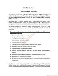
1.3 OVERVIEW OF WASTE WATER<br />
<strong>TREATMENT</strong><br />
Waste water treatment can involve physical,<br />
chemical or biological processes or combinations<br />
of these processes depending on the required<br />
outflow standards. A generalised layout of a<br />
waste water treatment plant is shown in Figure<br />
1.1.<br />
The first stage of waste water treatment takes<br />
place in the preliminary treatment plant where<br />
material such as oils, fats, grease, grit, rags and<br />
large solids are removed. These processes are<br />
described in greater detail in the preliminary<br />
treatment manual (EPA, 1995).<br />
Primary settlement is sometimes used prior to<br />
biological treatment. Radial or horizontal flow<br />
tanks are normally employed to reduce the<br />
velocity of flow of the waste water such that a<br />
proportion of suspended matter settles out.<br />
Biological treatment of waste waters takes place<br />
in fixed media or suspended growth reactors<br />
using activated sludge, biofiltration, rotating<br />
biological contactors, constructed wetlands or<br />
variants of these processes.<br />
Nitrification/denitrification and biological<br />
phosphorus removal can be incorporated at this<br />
stage and will reduce nutrient concentrations in<br />
the outflow.<br />
Chemical treatment is used to improve the settling<br />
abilities of suspended solids prior to a solids<br />
removal stage or to adjust the properties or<br />
components of waste water prior to biological<br />
treatment (e.g. pH adjustment, reduction of heavy<br />
metals or nutrient adjustment). It may also be<br />
used for precipitating phosphorus in conjunction<br />
with biological phosphorus treatment.<br />
Secondary settlement separates the sludge solids<br />
from the outflow of the biological stage.<br />
Tertiary treatment refers to processes which are<br />
used to further reduce parameter values below the<br />
standards set out in national regulations. The<br />
term is often used in reference to nutrient<br />
removal.<br />
Sludge treatment can be a significant part of a<br />
waste water treatment plant and involves the<br />
stabilisation and/or thickening and dewatering of<br />
sludge prior to reuse or disposal.<br />
1.4 ROLE OF THE PLANT OPERATOR<br />
Individual sections of this manual outline the role<br />
of the plant operator in the management,<br />
maintenance and operation of each process.<br />
The plant operator should manage the plant with<br />
the following objectives:<br />
where required, meeting the emission limits<br />
set in the UWWT Regulations for secondary<br />
treatment systems;<br />
meeting the standards for sensitive waters<br />
where prescribed;<br />
minimising odours and thus<br />
nuisance complaints;<br />
avoiding<br />
operating the waste water treatment plant<br />
efficiently;<br />
minimising energy consumption; and<br />
implementing an effective preventative<br />
maintenance programme.<br />
For additional advice on the operation and<br />
maintenance of plants, reference should be made<br />
to:<br />
the manufacturers' and suppliers' manuals of<br />
operation; and<br />
the training programmes implemented by the<br />
Tipperary (N.R.) County Council/FAS<br />
training group.
Stormwater<br />
balancing/storage<br />
Receiving water<br />
Storm Water Return<br />
Process<br />
recycle<br />
Collection network<br />
Pretreatment works<br />
and stormwater overflow<br />
1 <strong>TREATMENT</strong> OF WASTE WATER 3<br />
Processes described<br />
in this manual<br />
FIGuRE 1.1 WASTE WATER <strong>TREATMENT</strong> PLANT OVERVIEW<br />
r<br />
+<br />
Primary sedimentation<br />
Biological treatment<br />
*___<br />
Sludge Liquors Return<br />
RAS<br />
%<br />
— —<br />
J Sludge • Secondary settlement<br />
or clarification<br />
treatment/storage<br />
4<br />
— i<br />
r--+<br />
Nutrient removal Sludge re-use/disposal<br />
— — — — Sludge<br />
Waste water<br />
I
4 <strong>TREATMENT</strong> OF WASTE WATER
2 GENERAL CONSIDERATIONS 5<br />
2. GENERAL CONSIDERATIONS FOR THE <strong>TREATMENT</strong><br />
OF WASTE WATER<br />
2.1 CHARACTERISTICS OF URBAN<br />
WASTE WATER<br />
Urban waste water is characterised in terms of its<br />
physical, chemical and biological constituents.<br />
These characteristics and their sources are listed<br />
in Table 2.1.<br />
The strength of waste water is normally measured<br />
using accurate analytical techniques. The more<br />
common analyses used to characterise waste<br />
water entering and leaving a plant are:<br />
• BOD5<br />
• COD<br />
• TSS<br />
• pH<br />
• total phosphorus<br />
• total nitrogen<br />
2.2 PARAMETERS BY WHICH WASTE<br />
WATER IS MEASURED<br />
Biochemical oxygen demand (BOD): BOD is<br />
the amount of oxygen used by organisms while<br />
consuming organic matter in a waste water<br />
sample. It is possible to assess the performance<br />
of a waste water treatment plant by measuring the<br />
BOD5 of the inflow and the outflow. Many<br />
factors can influence this test, such as temperature<br />
of incubation, dilution rate, nitrification, toxic<br />
substances, nature of bacterial seed and presence<br />
of anaerobic organisms.<br />
The method of measurement for the BOD5 test in<br />
the UWWT Regulations requires:<br />
• that the sample is homogenised, unfiltered<br />
and undecanted; and<br />
• that a nitrification inhibitor is added.<br />
The UWWT Regulations allow for the BOD5 test<br />
to be replaced by another parameter, total organic<br />
carbon (TOC) or total oxygen demand (TOD) if a<br />
relationship can be established between BOD5<br />
and the substitute parameter.<br />
Chemical oxygen demand (COD): The COD<br />
test uses the oxidising agent potassium<br />
dichromate (specified in the UWWT Regulations)<br />
to oxidise organic matter in the sample. The test<br />
is extensively used because it takes less time<br />
(about 3 hours) than other tests such as the BOD5,<br />
which takes 5 days. The COD test does not,<br />
however, differentiate between biodegradable and<br />
non-biodegradable organic matter.<br />
For municipal waste water it is generally possible<br />
to establish a relationship between COD and<br />
BOD. Once a correlation has been established,<br />
the COD test can be a very useful indicator for<br />
the operation and control of the plant.<br />
Total suspended solids (TSS): This is the sum<br />
of the organic and inorganic solids concentrations<br />
and can be subdivided into:<br />
suspended which represent the solids that are<br />
solids: in suspension in the water.<br />
Generally comprised of 70%<br />
organic and 30% inorganic solids<br />
and can be removed by physical or<br />
mechanical means.<br />
organic about 50% of solids present in<br />
solids: urban waste water derive from the<br />
waste products of animal and<br />
vegetable life. Sometimes called<br />
the combustible fraction or volatile<br />
solids as these can be driven off by<br />
high temperature.<br />
inorganic these substances are inert and are<br />
solids: not subject to decay. Include sand,<br />
gravel and silt.<br />
settleable this is a subset of suspended solids<br />
solids: and represents that fraction of<br />
suspended solids that will settle in a<br />
given period.<br />
colloidal<br />
suspended<br />
solids:<br />
these refer to solids that are not<br />
truly dissolved and yet do not settle<br />
readily. They tend to refer to<br />
organic and inorganic solids that<br />
rapidly decay.<br />
Dissolved solids refers to that fraction of solids<br />
that pass through a 0.45 jim filter paper.
6 <strong>TREATMENT</strong> OF WASTE WATER<br />
TABLE 2.1 PHYSICAL AND CHEMICAL CHARACTERISTICS OF WASTE WATER AND THEIR SOURCES<br />
Colour<br />
CHARACTERISTIC<br />
Physical properties<br />
(Mod. Metcalf& Eddy, 1991)<br />
SOURCES<br />
Odour Decomposing waste water, industrial waste water<br />
Solids Domestic water supply, domestic and industrial<br />
waste water, soil erosion, inflow/infiltration<br />
Chemical constituents<br />
Organic:<br />
Carbohydrates, fats, oils and grease,<br />
proteins, surfactants, volatile organics<br />
Pesticides<br />
Phenols<br />
Other<br />
Inorganic:<br />
Alkalinity, chlorides<br />
Temperature<br />
Heavy metals<br />
Nitrogen<br />
pH<br />
Phosphorus<br />
Gases<br />
Hydrogen sulphides, methane<br />
Oxygen<br />
pH: This is the concentration of hydrogen ions in<br />
solution and indicates the level of acidity or<br />
alkalinity of an aqueous solution. If the pH of the<br />
waste water is outside the range 5-10, there may<br />
be considerable interference with biological<br />
processes. Figure 2.1 illustrates the effect of pH<br />
on bacterial growth.<br />
5 6<br />
7<br />
pH<br />
8 9<br />
FIGURE 2.1 GROWTH RATE OF MICRO-<br />
ORGANISMS AS A FUNCTION OF pH<br />
Domestic and industrial waste water, natural decay<br />
of organic materials<br />
Domestic and industrial waste water<br />
Domestic, commercial and industrial waste water<br />
Agricultural waste water<br />
Industrial waste water<br />
Natural decay of organic materials<br />
Domestic waste water, domestic water supply,<br />
groundwater infiltration<br />
Industrial waste water<br />
Domestic and agricultural waste water<br />
Domestic, commercial and industrial waste water<br />
Domestic, commercial and industrial waste water<br />
natural runoff<br />
Decomposition of urban waste water<br />
Domestic water supply, surface-water infiltration<br />
Total phosphorus: This parameter is normally<br />
divided into three fractions, namely:<br />
orthophosphate:<br />
dissolved inorganic<br />
phosphate (P043)<br />
polyphosphates: complex compounds<br />
generally derived from<br />
detergents<br />
organically<br />
bound phosphate:<br />
dissolved and suspended<br />
organic phosphates<br />
Total phosphorus analysis requires two steps:<br />
conversion of polyphosphates and<br />
organically bound phosphorus to dissolved<br />
orthophosphate, and<br />
colonmetric determination of the dissolved<br />
orthophosphate.<br />
-
100%<br />
99.9%<br />
1000mg/i<br />
4<br />
800 mg/I<br />
4 70mg/I<br />
200 mg/i<br />
130 mg/I<br />
FIGURE 2.2 TYPICAL COMPOSITION OF URBAN WASTE WATER<br />
(U.S.EPA, volume 1, 1992.)<br />
In instances where phosphorus is a growth<br />
limiting nutrient the discharge of waste water<br />
containing phosphorus may stimulate the growth<br />
of vegetation in the water body. The third<br />
schedule of the UWWT Regulations specifies a<br />
total phosphorus limit for discharges to sensitive<br />
water bodies.<br />
Total Nitrogen: This refers to the sum of<br />
measurements of total oxidised nitrogen (nitrate<br />
and nitrite) and total Kjeldahl nitrogen (ammonia<br />
and organic nitrogen). This parameter is a growth<br />
limiting nutrient in marine environments and a<br />
limit is specified in the UWWT Regulations for<br />
discharges to sensitive water bodies.<br />
BOD(C) : Nitrogen(N) : Phosphorus(P) ratio:<br />
In order to operate satisfactorily, micro-organisms<br />
require a balanced diet. This is normally<br />
achieved by niaintaining the level of BOD:N:P in<br />
the waste water at about the ratio 100:5:1.<br />
Domestic sewage is not normally deficient in<br />
these elements but industrial effluents may be and<br />
this can lead to a nutrient deficiency in the inflow<br />
to a plant. To monitor the BOD:N:P ratio the<br />
BOD, total nitrogen and total phosphorus<br />
analytical results are used.<br />
Water<br />
Dissolved<br />
solids<br />
Non-settleable<br />
solids (colloidal)<br />
2 GENERAL CONSIDERATIONS 7<br />
2.3 LABORATORY ACCREDITATION<br />
It is desirable that laboratories undertaking<br />
analyses be certified by a third party accreditation<br />
scheme such as that administered by the National<br />
Accreditation Board.<br />
As a step towards formal accreditation, the<br />
<strong>Agency</strong> has established a laboratory inter-<br />
calibration programme. This programme is<br />
designed to measure the performance and<br />
proficiency of each participating laboratory on a<br />
regular basis by objectively reviewing the<br />
analytical results produced. Identical samples are<br />
sent to participating laboratories and the results<br />
compared to each other. Duplicate analyses are<br />
also undertaken by the participating laboratories<br />
to estimate the precision of the results within each<br />
laboratory.<br />
Appendix A provides examples of forms which<br />
operators are encouraged to use in order to<br />
standardise analyses and reporting.<br />
2.4 PLANT LOADING<br />
Measurement of the inflow and composition of<br />
waste water is of critical importance to the design
8 <strong>TREATMENT</strong> OF WASTE WATER<br />
and operation of both the collection system and<br />
the treatment plant.<br />
For large scale treatment plants, it is common to<br />
design the plant for a maximum 3 times Dry<br />
Weather Flow (DWF). On smaller plants, the<br />
scale of plant and the cost implications of a<br />
higher design coefficient are less significant and<br />
the figure is normally taken as 4 to 6 times DWF<br />
depending on whether the sewerage system is<br />
combined or partially separate. This approach is<br />
generally followed for treatment plants up to<br />
2,000 p.e. and may well be desirable up to at least<br />
5,000 p.e.<br />
2.4.1 HYDRAULIC LOADING<br />
The flow entering an urban waste water treatment<br />
plant includes:<br />
domestic waste water;<br />
industrial waste water discharges: data can be<br />
obtained from discharge licences issued in<br />
accordance with the Local Government<br />
120<br />
100<br />
80<br />
60<br />
40<br />
20<br />
nteter<br />
(Water Pollution) Acts 1977 and 1990 or the<br />
IPC licence issued under the EPA Act, 1992.<br />
Alternatively, an industry's metered water<br />
consumption figures can be used:<br />
infiltration:<br />
surface water and storm water (except in<br />
separate systems).<br />
The flow entering a plant can vary from hour to<br />
hour. day to day, week to week and season to<br />
season. Figure 2.3 illustrates an example of<br />
diurnal flow variation.<br />
Appendix B contains a summary table of the<br />
characteristics of some common industrial<br />
discharges.<br />
2.4.2 ORGANIC LOADING<br />
The organic loading entering the waste water<br />
treatment plant will be determined by the volume<br />
and strength of the industrial waste water in<br />
addition to the population served.<br />
0 I I I I I I I I I I I<br />
00:00 02:00 (1)4:00 06:00 08:00 10:00 12:00 14:00 16:00 18:00 20:00 22:00<br />
Hours<br />
FIGURE 2.3 DIURNAL AND SEASONAL FLOW VARIATIONS TO A <strong>TREATMENT</strong> PLANT
,<br />
The UWWT Regulations define one population<br />
equivalent (p.e.) as the load resulting from 60g of<br />
BOD5. The Regulations prescribe that the<br />
population equivalent of a plant (organic load) is<br />
to be "calculated on the basis of the maximum<br />
average weekly load entering the treatment plant<br />
during the year, excluding unusual situations such<br />
as those due to heavy rain".<br />
Industrial and domestic loads may be seasonal<br />
and hence it is important that the organic load<br />
entering the plant is accurately measured. The<br />
COD test in particular is a fast and reliable<br />
method of establishing the organic load<br />
contributed from an industrial premises. The<br />
COD test results should always be used in<br />
addition to the BOD5 test results.<br />
Typical values of the principal constituents of<br />
urban waste water are given in Table 2.2<br />
TABLE 2.2 TYPICAL CHARACTERISTICS OF<br />
URBAN WASTE WATER<br />
Parameter<br />
Concentration<br />
mg/I<br />
BOD 100-300<br />
COD 250 - 800<br />
Suspended solids 100 - 350<br />
Total nitrogen (as N)<br />
20 - 85<br />
Ammonia (NH3 as N) 10 - 30<br />
Organic phosphorus (as P)<br />
1 - 2<br />
Inorganic phosphorus (as P) 3 - 10<br />
Oils, fats and grease<br />
Total inorganic constituents<br />
(Na, Cl, Mg, S, Ca, K, Si, Fe)<br />
Heavy metals (Cd, Cr, Cu,<br />
Pb, Hg, Ni, Ag, Zn)<br />
50 - 100<br />
100 •<br />
10 <strong>TREATMENT</strong> OF WASTE WATER<br />
• the need to take a sample at the probe for<br />
calibration purposes;<br />
•<br />
servicing and maintenance;<br />
stray light causing erroneous results; and<br />
air bubbles in the sample.<br />
Dissolved oxygen (DO) meters are used to<br />
monitor levels of oxygen available in the aeration<br />
tank to sustain biological activity. Suspended and<br />
dissolved solids and some gases such as chlorine,<br />
hydrogen sulphide, carbon dioxide and sulphur<br />
dioxide can interfere with the measurement of<br />
dissolved oxygen.<br />
The following basic information should be<br />
retained at the plant for each instrument being<br />
used:<br />
a the manufacturer;<br />
a the type, model and serial number;<br />
the date of installation; and<br />
• the maintenance and calibration manual.<br />
The accuracy of a probe should be obtained from<br />
the manufacturer's literature. Accuracy expresses<br />
how close a probe reading is to the true value of<br />
the parameter being measured.<br />
For optimum performance, probes should be<br />
regularly cleaned.<br />
2.6 TELEMETRY<br />
Telemetry is the remote interrogation of a process<br />
plant for the control of equipment and the<br />
monitoring of parameters. For small treatment<br />
plants where the cost of continuous human<br />
presence for control and monitoring purposes<br />
would be excessive, consideration should be<br />
given to its use. Telemetry links are important as<br />
incidents arising at small treatment plants may<br />
have severe repercussions if not corrected<br />
quickly. Examples include the breakdown of<br />
aeration equipment or the escape of sludges over<br />
secondary settlement tank weirs.<br />
Techniques available for the transmission of data<br />
include:<br />
• private telephone lines;<br />
• leased telephone lines;<br />
modems via standard telecommunication<br />
line; and<br />
VHF radio.<br />
Such systems (or combination of systems) are<br />
highly practical for short duration transmissions<br />
such as calling out personnel after a specified<br />
incident has occurred. In remote situations where<br />
telephone links are not practical, radio based<br />
systems should be considered.<br />
2.7 SCADA SYSTEMS<br />
There are a number of variables that can be<br />
measured and controlled on a waste water<br />
treatment plant. These include:<br />
physical parameters (e.g. flow, pressure,<br />
temperature);<br />
chemical parameters (e.g. pH, turbidity, DO);<br />
and<br />
biological parameters (e.g. sludge growth<br />
rate).<br />
Process control systems like 'Supervisory Control<br />
and Data Acquisition' (SCADA) monitor these<br />
variables and implement actions in response. The<br />
systems typically include:<br />
a measurement instrument for the variable(s);<br />
a signal transmitting device;<br />
a computer display;<br />
a control loop; and<br />
a controller.<br />
The system can be designed to meet requirements<br />
unique to a plant. SCADA systems typically<br />
monitor and control all streams through the plant<br />
and archive the data received.<br />
2.8 INSTRUMENTATION AND CONTROL<br />
SYSTEMS<br />
The level of instrumentation and computer<br />
control required at a waste water treatment plant<br />
will essentially depend on:<br />
the size and complexity of the plant;<br />
the number of operators required and their<br />
skills;<br />
any process data needed for problem solving;<br />
the costs involved;<br />
the hours of manned operation;<br />
the qualifications of personnel available<br />
(including instrumentation people); and
the type of control: manual, supervisory,<br />
automatic or computer control.<br />
If automatic controls are selected, decisions<br />
should be made concerning the number of control<br />
elements and loops, the accuracy needed, the<br />
operating range, the response time of process<br />
variables and the frequency of operator input.<br />
The economics of instrumentation and controls<br />
should be compared with the savings achieved by<br />
plant automation.<br />
2 GENERAL CONSIDERATIONS 11
12 <strong>TREATMENT</strong> OF WASTE WATER
3 BioioGicL <strong>TREATMENT</strong> 13<br />
3. BIOLOGICAL <strong>TREATMENT</strong> OF WASTE WATERS<br />
3.1 WASTE WATER FLORA AND FAUNA<br />
The biology of waste water treatment is based on<br />
the consumption of organic matter by micro-<br />
organisms which include bacteria, viruses, algae<br />
and protozoa. An operator's job is to regulate<br />
these micro-organisms so that they perform in an<br />
efficient and economic way. Therefore, a<br />
knowledge of their metabolism is necessary in<br />
order to control the process effectively.<br />
Bacteria are the most populous of the micro-<br />
organisms used in waste water treatment; these<br />
single-celled organisms directly break down the<br />
polluting matter in waste waters. Bacteria are<br />
lower life forms and occupy the bottom of the<br />
waste water treatment food chain. Bacteria can be<br />
sub-divided into different groups but in all cases<br />
their metabolism is based on the mechanism<br />
illustrated in Figure 3.1. Enzymes, both internal<br />
and external, are used to break down the substrate<br />
(food) into a form which can be more readily used<br />
by the bacteria for the maintenance and<br />
propagation of life. For aerobic bacteria, oxygen<br />
is required in breaking down the substrate.<br />
Anaerobic bacteria operate in the absence of<br />
oxygen. Facultative micro-organisms have the<br />
ability to operate aerobically or anaerobically.<br />
Heterotrophic bacteria break down organic<br />
material like carbohydrates, fats and proteins;<br />
these are characterised by the BOD and COD of a<br />
waste water. These compounds are generally<br />
easily biodegradable and so the bacteria thrive<br />
and enjoy high growth rates; their doubling time<br />
can be measured in hours (and sometimes<br />
minutes). The two basic reactions for<br />
carbonaceous oxidation can be represented as<br />
follows:<br />
(i) Organic matter + 02<br />
bacteria + CO2 + H2O + Energy<br />
enzyme<br />
(ii) Organic matter + P + NH3 + 02 + Energy<br />
bacter, New cell material<br />
enzyme<br />
Autotrophic bacteria derive their cell carbon from<br />
CO2 and use a non-organic source of energy for<br />
growth. Nitrifying bacteria oxidise ammonia<br />
(which is either present in the waste water or is<br />
produced from the breakdown of proteins and<br />
other nitrogen rich organic compounds) to nitrite<br />
and nitrate under aerobic conditions. These<br />
bacteria tend to be slower growing than the<br />
heterotrophs. They are sensitive to environmental<br />
changes such as toxic shock loads.<br />
H + Nitrosomonas<br />
1N 4+5 2<br />
2N02 + 2H2O + 4H + Energy<br />
2NO2 + 02 Nttro barter > 2NO3 + Energy<br />
Under anoxic conditions, many heterotrophic<br />
bacteria have the ability in the absence of<br />
dissolved molecular oxygen to utilise the oxygen<br />
contained in nitrate molecules. Nitrate is reduced<br />
to nitrogen gas during these denitrification<br />
reactions and the gas bubbles away to<br />
atmosphere.<br />
Anaerobic bacteria thrive in the absence of<br />
oxygen and, in urban waste water treatment<br />
plants, are most often encountered under septic<br />
conditions where oxygen is not available or has<br />
become depleted, for example in long sewers or<br />
in sludge storage tanks. Foul odours are<br />
generally associated with septic conditions.<br />
Anaerobic processes are most commonly used for<br />
the pretreatment of high strength industrial wastes<br />
and for the digestion of sludges.<br />
Higher life forms in the waste water treatment<br />
food chain include protozoa and rotifers. These<br />
are illustrated in Figure 3.2. These animals<br />
require time to become established in a treatment<br />
facility and will appear and predominate in the<br />
order of flagellates, free swimming ciliates,<br />
stalked ciliates and rotifers. Their function is to<br />
prey on bacteria and on larger solid particles that<br />
have not been consumed by bacteria. They<br />
consume any loose suspended material thus<br />
ensuring a clear outflow. The relative quantity of<br />
these animals when viewed through a microscope<br />
is an excellent indicator of the state of health of a<br />
biological treatment system and in the hands of an<br />
experienced operator can be as indicative as<br />
chemical analyses.
14 <strong>TREATMENT</strong> OF WASTE WATER<br />
New cells -<br />
Bacterial and protozoan populations do not exist<br />
in isolation; they interact, causing modifications<br />
to each other's population and activities.<br />
Although protozoa remove bacteria by predation,<br />
treatment of waste water occurs at a faster rate<br />
when both classes of micro-organism are k<br />
present.<br />
Stalked<br />
ciliates<br />
Amoeba<br />
FIGuRE 3.2 EXAMPLES OF PROTOZOA AND<br />
ROTIFERA<br />
organics<br />
Still higher in the food chain are nematodes and<br />
higher worms, snails and insects. Figure 3.3<br />
illustrates the inter-relationship between the<br />
ftO jProductsof<br />
respiration<br />
animals important to waste water treatment and<br />
their relative abundance.<br />
3.2 BACTERIAL GROWTH<br />
Under batch conditions bacterial growth can be<br />
predicted using the growth curve illustrated in<br />
Figure 3.4. At time zero, the bacteria begin to<br />
absorb substrate. As energy becomes available<br />
for reproduction, the bacterial population will<br />
increase at an exponential rate. The substrate is<br />
consumed at high rates until it becomes limiting,<br />
i.e. it is in short supply. The metabolism of the<br />
bacteria then slows down to a conventional rate<br />
and will eventually become stationary. In this<br />
mode sufficient substrate exists only to maintain<br />
life, not to promote growth. As the shortage of<br />
substrate becomes more critical, bacteria die off<br />
and other bacteria feed on the dead cells. This<br />
process is called endogenous respiration or<br />
cryptic growth<br />
Free<br />
particle<br />
FIGURE 3.1 METABOLISM AND TRANSPORT MECHANISMS IN BACTERIAL CELLS<br />
(CRS Group, 1978)<br />
Free<br />
swimming<br />
Flagellate ciliate<br />
Rotifer<br />
and results in a decrease in the<br />
mass of bacteria. At this point, if a bacterial mass<br />
is returned to a food rich environment, the cycle<br />
will begin again.<br />
Many bacterial processes are continuous and<br />
operate, theoretically, at a constant food loading<br />
rate at a particular point on the curve. Every<br />
effort should be made to control a process at the<br />
desired point in order to maintain the bacterial<br />
population in an unstressed condition.
1<br />
Higher life forms<br />
Lower life forms<br />
Percolating filter<br />
process<br />
E<br />
I-<br />
C<br />
sects and worms<br />
3 BIOLOGICAL <strong>TREATMENT</strong> 15<br />
FIGURE 3.3 RELATIVE PREDOMINANCE OF ORGANISMS USED IN WASTE WATER <strong>TREATMENT</strong><br />
(Wheatley, 1985)<br />
Lag Exponential Declining growth<br />
phase or log growth and stationary<br />
Conventional<br />
aeration zone<br />
Contact time<br />
Endogenous respiration<br />
Extended<br />
aeration zone<br />
FIGuRE 3.4 BACTERIAL GROWFH CURVE<br />
)trophlc bacteria, fungi<br />
uspended & dissolved<br />
Tganic matter
16 <strong>TREATMENT</strong> OF WASTE WATER<br />
3.3 INHIBITION<br />
The performance of the waste water treatment<br />
plant is dependent upon the activity of micro-<br />
organisms and their metabolism which can be<br />
dramatically affected by the presence of toxic<br />
material in the raw waste water. The extent to<br />
which inhibition may cause a problem in waste<br />
water treatment plant depends, to a large extent.<br />
on the constituents of the waste water undergoing<br />
treatment. Many materials such as organic and<br />
inorganic solvents, heavy metals and biocides can<br />
inhibit the biological activity in the treatment<br />
plant.<br />
Table 3.1 lists the inhibitory levels reported for<br />
some metals, inorganic and organic substances.<br />
The discharge of these materials from industrial<br />
activities should be controlled under the licensing<br />
provisions of the Local Government (Water<br />
Pollution) Acts, 1977 and 1990, and the<br />
<strong>Environmental</strong> <strong>Protection</strong> <strong>Agency</strong> Act, 1992.<br />
There are two forms of toxicity: acute and<br />
chronic.<br />
Acute toxicity occurs when the level of toxic<br />
material in the waste water is high enough to<br />
inactivate the biological activity. This happens<br />
rapidly. Chronic toxicity occurs slowly (over<br />
days or weeks) and results in process failure due<br />
to a gradual accumulation of toxic material in the<br />
biomass.<br />
Toxic materials in the waste water can selectively<br />
inhibit single species of micro-organism. For<br />
example, inhibition of one species of bacteria in<br />
the two species chain responsible for nitrification<br />
can lead to nitrite rather than nitrate being present<br />
in the outflow. Damage to protozoa in the<br />
activated sludge process can lead to a turbid<br />
outflow which may persist for days while damage<br />
to grazing micro-organisms in a percolating filter<br />
(e.g. protozoa, rotifers) will take time to exhibit<br />
itself but may eventually result in clogging of the<br />
filter media.<br />
The net effect of inhibition is an increase in the<br />
plant loading. A toxin with an EC50 (Effective<br />
Concentration which causes 50% toxicity) of<br />
6.7% means that a 6.7% solution of the toxin in<br />
the waste water would cause 50% inhibition. A<br />
(6.7150%=) 0.134% solution would cause 1%<br />
inhibition, thereby adding 1% to the effective<br />
BOD load to the plant.<br />
The toxicity of industrial discharges to micro-<br />
organisms is measured by respiration inhibition (a<br />
reduction in the 02 consumption rate) and its<br />
measurement should be considered where the<br />
treatment plant may be subject to shock loads of<br />
toxic material. The composition of waste water<br />
entering the treatment plant should be monitored<br />
on a daily basis. Industrial outflows and domestic<br />
waste waters may react with one another in the<br />
collection system and enhance or reduce the<br />
overall toxicity in an unpredictable way.<br />
Temperature and pH can also, individually or in<br />
combination, affect the biological activity in the<br />
plant. Other materials such as oils, fats, grease<br />
and hair can affect the operation of mechanical<br />
plant. Where significant levels of such materials<br />
are present in an industrial discharge,<br />
consideration should be given to the installation<br />
of pretreatment devices (such as screens, oil<br />
separators or dissolved air flotation) or<br />
monitoring equipment (in the case of temperature<br />
and pH) in order to control their discharge to the<br />
foul sewer.<br />
Appendix C lists some of the toxic and non-toxic<br />
parameters that are commonly associated with<br />
various industrial sectors. Where significant<br />
levels of toxicity are suspected in an industrial<br />
discharge entering the sewer, data on the<br />
respiration rate and microbial inhibition potential<br />
should be obtained.
18 <strong>TREATMENT</strong> OF WASTE WATER
4. PRIMARY <strong>TREATMENT</strong> OF WASTE WATER<br />
4.1 PROCESS DESCRIPTION<br />
Conventional activated sludge units and<br />
percolating filters are normally preceded by<br />
treatment units commonly called primary<br />
sedimentation or settlement tanks or primary<br />
clarifiers.<br />
Settlement tanks that follow biological treatment<br />
are called secondary settlement tanks or final<br />
clanfiers and these units separate solids that have<br />
been generated through biological activity.<br />
Primary and secondary settlement tanks operate in<br />
almost exactly the same way; the main difference<br />
is the density of the sludge they handle. Primary<br />
sludges are usually more dense (and more<br />
unstable) than secondary sludges. The<br />
supernatant from the secondary settlement tank is<br />
clearer than that from the primary settlement tank.<br />
The manner in which solids settle out in a<br />
settlement tank is of vital importance to the<br />
operation of the waste water treatment plant.<br />
There are four types of settlement which are<br />
dependent on the type of solids present in the<br />
liquid. These are:<br />
• discrete<br />
settling:<br />
this applies to sand and grit,<br />
where the particles' physical<br />
properties such as specific<br />
gravity, shape<br />
and size<br />
remain constant during<br />
settlement;<br />
• flocculent settling particles join<br />
settling: together increasing their<br />
density and settling ability.<br />
This type of settlement is<br />
associated with primary<br />
settlement tanks;<br />
• hindered<br />
settling:<br />
this is associated with the<br />
settlement of activated<br />
sludge, where particles form<br />
a blanket which then settles<br />
and consolidates as a mass;<br />
• compression<br />
settling:<br />
4 PRIMARY <strong>TREATMENT</strong> 19<br />
€ompression of particles is<br />
very slow and is only made<br />
possible by the weight of<br />
new particles pressing down<br />
on the sludge layer.<br />
Figure 4.1 illustrates the settling pattern that<br />
occurs when a uniform but concentrated<br />
suspension is placed in a graduated cylinder.<br />
FIGURE 4.1 SErFLING THEORY<br />
In practice, it is common for all four types of<br />
settlement to occur in a settlement tank<br />
simultaneously. The settlement of solids is<br />
concentration dependent and in situations where<br />
high suspended solids are present, both hindered<br />
and compression settling can occur in addition to<br />
discrete and flocculent settling.<br />
4.2 PRIMARY SETTLEMENT TANKS<br />
Primary settlement tanks are generally circular or<br />
rectangular in shape and are illustrated in Figure<br />
4.2 and Figure 4.3 respectively. Their purpose is<br />
to reduce the velocity of the incoming waste<br />
water stream thereby allowing the settleable<br />
solids to fall to the bottom of the tank.<br />
Typically, 50-70% of suspended solids are<br />
removed in primary settlement tanks. In addition,<br />
BOD is reduced by 20-50% and the bacterial<br />
count by 25-75%. The pH is generally unaffected<br />
by primary settlement.
20 <strong>TREATMENT</strong> OF WASTE WATER<br />
Rotary sludge<br />
scraper<br />
Part H<br />
Stilling box Reduces the velocity and distributes flow radially through the tank.<br />
Outflow weir Ensures equal flow along the periphery of the outflow channel.<br />
Outflow channel<br />
Rotary sludge scraper<br />
Collects the outflow and carries it to the next treatment stage.<br />
Moves the sludge down the floor slope to the collection hopper.<br />
Scum baffle Extends above the water surface and prevents floating material from reaching the<br />
outflow channel. The collected scum is directed by a surface skimmer to a scum<br />
box from where it is typically discharged with the excess sludge.<br />
The efficiency of the primary settlement tank is<br />
dependent on a number of factors, including:<br />
FIGURE 4.2 CIRCULAR RADIAL FLOW SETTLEMENT TANK<br />
• the type of solids present inthe waste water:<br />
this will typically be influenced by the type<br />
and quantity of industrial waste entering the<br />
plant;<br />
• the length of time the waste water is in the<br />
collecting system: degradation of the waste<br />
water can generate gas bubbles (H2S) as a<br />
result of anaerobic conditions and this can<br />
affect the settlement of solids;<br />
• design criteria being exceeded: the most<br />
important criteria being the retention time in<br />
the tank which is usually about 2 hours at<br />
maximum flow, the overflow (surface<br />
loading) rate which is typically 28.8-36<br />
m3/m2/day (at peak flow) and the weir<br />
overflow rate measured in m3/mlday;<br />
• sludge withdrawal: sludge should be<br />
removed regularly to prevent septicity which<br />
can cause floating sludge: and<br />
return liquors from other treatment stages<br />
(e.g. sludge dewatering) which may contain<br />
suspended solids with varying settlement<br />
qualities.<br />
Notwithstanding the above, primary sludge lends<br />
itself well to anaerobic digestion and resource<br />
recovery as well as to the production of well<br />
stabilised sludges. Resource recovery (i.e.<br />
methane gas) is economically viable because of<br />
the high level of substrate available as opposed to<br />
waste activated sludge where the substrate has<br />
already been substantially digested.<br />
4.3 SEPTIC TANKS AND IMHOFF TANKS<br />
The oldest type of primary treatment is the septic<br />
tank which has been often used to provide waste<br />
water treatment for single houses and small<br />
communities. The conventional system consists<br />
of a septic tank and a percolation area.<br />
Percolation areas are also known as seepage<br />
fields or beds, subsurface areas or soil absorption<br />
systems.
Sludge<br />
outlet<br />
Part<br />
Influent<br />
Purpose<br />
4 PRIMARY <strong>TREATMENT</strong> 21<br />
Inlet baffle Distributes the inflow evenly and prevents short-circuiting along the tank<br />
surface.<br />
Outflow weir Ensures equal flow along the length of the outflow channel.<br />
Outflow channel Collects the outflow and carries it to the next treatment stage.<br />
Sludge scraper<br />
Inlet baffle<br />
Sludge<br />
- hopper—<br />
A<br />
Moves the sludge along the floor to collection hopper.<br />
Scum baffle Extends above the water surface and prevents floating material from reaching<br />
the outflow channel. The collected scum is directed by a surface skimmer to a<br />
scum box from where it is typically discharged with the excess sludge.<br />
FIGURE 4.3 RECTANGULAR HORIZONTAL FLOW SETTLEMENT TANK<br />
The main function of a septic tank is to act as a<br />
primary settlement tank removing some of the<br />
BOD and the majority of the suspended solids<br />
from the waste water; the removal of suspended<br />
solids significantly reduces the extent of clogging<br />
in the subsurface percolation area.<br />
The extra chamber of an Imhoff tank prevents the<br />
re-suspension of settled solids and allows for their<br />
decomposition in the same unit.<br />
Figure 4.4 shows a typical cross section of an<br />
Imhoff tank. Waste water flows through the<br />
upper compartment and the settled solids are<br />
allowed to digest in the lower compartment. The<br />
compartments are partially separated from each<br />
other thus preventing digestion gases or digesting<br />
sludge particles in the lower section from<br />
entering/returning to the upper section. Any gas<br />
or sOlids rising are routed to the gas vent or scum<br />
outlet.<br />
Chemical treatment can be used to enhance<br />
settlement in the these tanks. Chemicals such as<br />
I<br />
Scum baffle<br />
__ J<br />
direction flow<br />
— HD H<br />
Sludge scraper mechanism<br />
aluminium sulphate (alum), ferric chloride, lime<br />
and polymer can be added to the incoming waste<br />
water to produce a floc, which will form an<br />
insoluble compound that adsorbs colloidal matter,<br />
attracts non-settleable suspended solids and<br />
encourages settlement.<br />
FIGURE 4.4 IMHOFF TANK<br />
Outflow<br />
weir<br />
Outflow<br />
i jnei<br />
Sludge<br />
draw off
22 <strong>TREATMENT</strong> OF WASTE WATER<br />
4.4 TUBE AND LAMELLA SETTLERS<br />
Inclined surfaces in a settlement tank increase the<br />
effective surface area available for settlement and<br />
also increase efficiency by more closely<br />
approximating to ideal settlement theory. The<br />
increased surface area is provided by a series of<br />
inclined plates (lamellae) or tubes (which may be<br />
circular, square, hexagonal or other) occupying<br />
up to 70% of the tank depth and lying less than 30<br />
cm beneath the water surface. Typical tube size<br />
or diameter is 25-50 mm. They are set at an angle<br />
greater than 40° so that settled sludge falls to the<br />
base of the tank from where it may be removed by<br />
conventional methods of desludging. Providing<br />
an increased available surface area can result in:<br />
the use of a smaller tank thereby saving<br />
capital costs; and<br />
an increased capacity in an overloaded tank by<br />
retrofitting.<br />
Lmdi ttk, Oprtoo ol nebooi o.bo<br />
FIGURE 4.5 INCLINED SETTLEMENT SYSTEM<br />
Ettlertt<br />
Some drawbacks of tube and lamella settlers<br />
include:<br />
• a tendency to clog due to an accumulation of<br />
fats and grease. These materials should be<br />
removed upstream;<br />
growth of plants and biofilms on the plates or<br />
tubes; and<br />
• the accumulation of sludge on the plate or<br />
tube surfaces which may cause septicity and<br />
the outflow quality to deteriorate.<br />
Tube and lamella settlement tanks should be<br />
frequently drained down and the plates or tubes<br />
cleaned to remove any accumulated material.<br />
Tube and lamella settlers are commonly used with<br />
package plants on a small scale in order to<br />
economise on space and costs. Due to a lack of<br />
storage capacity they may require more frequent<br />
desludging than other systems. They may be<br />
installed in circular settlement tanks but are more<br />
frequently used in new rectangular units.<br />
4.5 DISSOLVED AIR FLOTATION<br />
Dissolved air flotation (DAF) involves the<br />
dissOlution of air in waste water by pressurising it<br />
in a pressure vessel. When the air saturated waste<br />
water is released to the flotation tank, the sudden<br />
decrease in pressure causes the air to come out of<br />
solution as micro-bubbles which will attach<br />
themselves to solid particles in the waste water<br />
and make them float. The result is a floating mat<br />
of sludge on the surface which is skimmed off.<br />
Clarified waste water exits under a solids<br />
retention baffle. DAF tanks can be circular or<br />
rectangular in shape. As in a gravity settlement<br />
tank, the retention period must be long enough to<br />
allow for adequate separation of the solid and<br />
liquid fractions.<br />
A variation on the process called dispersed air<br />
flotation does not use expensive pressure vessels<br />
and pumps to entrain air in the waste water.<br />
Instead, mechanical devices such as rapidly<br />
rotating impellers incorporating air sparges<br />
provide small bubbles which will attach<br />
themselves to solid particles. This method is<br />
cheaper to purchase and operate and is generally<br />
available on a smaller scale for use in package<br />
plants.<br />
DAF is not commonly applied for the routine<br />
separation of solids and liquids in urban waste<br />
water but is more frequently<br />
used on difficult<br />
wastes or for the pretreatment of effluents, for<br />
example. in the removal of fats, oil and grease.<br />
Other applications have included the thickening<br />
of mixed liquor wasted directly from the activated<br />
sludge aeration basin.<br />
drretron el belt<br />
thickened<br />
nlndge<br />
FIGURE 4.6 DISSOLVED AIR FLOTATION
5. ACTIVATED SLUDGE (SUSPENDED GROWTH)<br />
PROCESSES<br />
5.1 PROCESS DESCRIPTION<br />
The activated sludge process was developed in<br />
1914 by Arden and Lockett. It was so called<br />
because it involved the produciion of an activated<br />
mass of micro-organisms capable of aerobically<br />
stabilising the organic content of a waste.<br />
Though many configurations of this process now<br />
exist, the basic units (Figure 5.1) have remained<br />
the same.<br />
Waste water is introduced into an aerated tank of<br />
micro-organisms which are collectively referred<br />
to as activated sludge or mixed liquor. Aeration is<br />
achieved by the use of submerged diffused or<br />
surface mechanical aeration or combinatidns<br />
thereof, which maintain the activated sludge in<br />
suspension. Following a period of contact<br />
between the waste water and the activated sludge,<br />
the outflow is separated from the sludge in a<br />
secondary settlement tank. To maintain the<br />
desired micro-biological mass in the aeration<br />
Q<br />
QR = return activated sludge, m3/day<br />
Qw = waste activated sludge, m3/day<br />
= aeration tank volume, m3<br />
Aeration tank<br />
V = secondary settlement tank volume, m3<br />
5 ACTIVATED SLUDGE 23<br />
tank, sludge is returned to the aeration tank<br />
(RAS) while an excess due to biological growth<br />
is periodically or continuously wasted (WAS).<br />
The concentration at which the mixed liquor is<br />
maintained in the aeration tank affects the<br />
efficiency of treatment.<br />
The basic unit of operation of the activated sludge<br />
process is the floe. The floe is suspended in the<br />
aeration tank and consists of millions of aerobic<br />
micro-organisms (bacteria, fungi, yeast, protozoa,<br />
and Worms), particles, coagulants and impurities<br />
that have come together and formed a mass. This<br />
mass is irregular in shape and helps to collect<br />
pollutants, both organic and inorganic, in the<br />
waste water by adsorption, absorption or<br />
entrapment. To operate the process on a<br />
continuous basis, the floe must be separated in the<br />
secondary settlement tank and returned to the<br />
aeration tank.<br />
Secondary<br />
settling tank<br />
Si Se<br />
Q = inflow, m3/day<br />
SR<br />
S, = inflow suspended solids, mg/I<br />
SR = return activated sludge suspended solids,<br />
mg/I<br />
S = waste activated sludge suspended solids,<br />
mg/I<br />
MLSS = mixed liquor suspended solids in the<br />
aeration tank, mg/I<br />
S = outflow suspended solids, mg/I<br />
FIGu1 5.1 ACTIVATED SLUDGE PROCESS
24 <strong>TREATMENT</strong> OF WASTE WATER<br />
Although all flocs have a specific gravity of<br />
approximately 1.0, only well developed flocs<br />
settle out in the secondary settlement tank, the<br />
remainder being carried over to the outflow (or to<br />
a tertiary treatment stage).<br />
Hydraulic retention time is critical in the aeration<br />
tank as the waste water needs adequate contact<br />
time with the floc to be "consumed" by what ever<br />
means.<br />
Well developed flocs consist of filamentous and<br />
non-filamentous organisms with the latter being<br />
the dominant species as these are better floc<br />
formers. A good mixed liquor will consist of<br />
light brown masses which tend to clump together<br />
and settle at a uniform rate. Microscopic<br />
examination will reveal very few flagellates and<br />
amoebae and a large number of free swimming<br />
ciliates and some stalked ciliates.<br />
To achieve the desired outflow quality objectives,<br />
the operator is required to react to several<br />
dynamic situations. These situations have inter-<br />
related factors some of which are:<br />
the characteristics of the inflow - including<br />
the hydraulic and organic loading rates;<br />
the amount of solids in the aeration tank;<br />
• the amount of oxygen needed to satisfy the<br />
respiratory requirements of the organisms<br />
present;<br />
• ensuring a suitable environment exists for the<br />
micro-organisms;<br />
• the volume of the aeration tanks and<br />
secondary settlement tanks required to<br />
accommodate seasonal variations; and<br />
the control and disposal of scum and<br />
supernatants.<br />
5.2 MIXED LIQUOR SUSPENDED SOLIDS<br />
The solids present in the aeration tank of an<br />
activated sludge process are termed mixed liquor<br />
suspended solids (MLSS) while the liquid<br />
suspension is called mixed liquor. MLSS<br />
concentrations are measured and used by<br />
operators to monitor the biomass levels present in<br />
the aeration tank. Different activated sludge<br />
processes operate at different MLSS values for<br />
different process objectives.<br />
The MLSS concentration is usually measured by<br />
filtering a small sample of mixed liquor through<br />
fibre glass filter paper. This is a crude method of<br />
monitoring the micro-organisms present in the<br />
system. However, the test does not distinguish<br />
between the organic and inorganic fraction of the<br />
solids. The convenience of the test, however.<br />
generally outweighs this disadvantage. The<br />
organic fraction can be analysed by subsequently<br />
burning off the organic fraction of the filtered<br />
sample at 500 ± 50°C.. This fraction is called the<br />
mixed liquor volatile suspended solids (MLVSS)<br />
and, like MLSS, is expressed as mg/I. For day to<br />
day monitoring of the waste water treatment plant<br />
the use of MLSS is sufficient.<br />
5.3 OXYGEN REQUIREMENTS AND<br />
TRANSFER<br />
Oxygen (dissolved in the mixed liquor) is<br />
required for respiration by the micro-organisms in<br />
the aeration tank. The activated sludge process<br />
depends on the activity of these aerobic micro-<br />
organisms and consequently, accurate control of<br />
oxygen in the aeration tank is vital.<br />
Too much or too little oxygen in the aeration tank<br />
is undesirable for different reasons. Too much<br />
oxygen adds unnecessary cost due to increased<br />
power consumption and too little can decrease the<br />
metabolism of the micro-organisms and the<br />
efficiency of the process.<br />
The oxygen added must:<br />
satisfy the inflow biological oxygen demand;<br />
and<br />
maintain a concentration of between I and 2<br />
mg/I dissolved oxygen in the mixed liquor.<br />
5.3.1 THEORY<br />
The theoretical oxygen requirement can be<br />
calculated by assuming that the biodegradable<br />
matter is converted to carbon dioxide, water and<br />
energy.<br />
If the simple sugar glucose is the only compound<br />
in the waste water, it is possible to estimate the<br />
exact oxygen requirement by writing down a<br />
balanced equation:<br />
C6H1206 + 6O — 6C02 + 6H20<br />
To completely oxidise one glucose molecule, 6<br />
molecules of oxygen are required. In reality<br />
however, such theoretical calculations become
5 ACTIVAtED SLUDGE 25<br />
complex because of the diversity of the chemical<br />
compounds found in waste water. Mechanical surface aerator with<br />
(or without) draft tube<br />
If nitrification is required, then the oxygen<br />
demand for the conversion of ammonia to nitrate<br />
must be taken into account.<br />
2NH4 + 302+ nitrifying bacteria — 2N02 + 4H+ 2H20 : •<br />
2N02 + 02 + nitrifying bacteria —* 2N0<br />
I<br />
,J 1\<br />
5.3.2 TYPES OF EQUIPMENT .4<br />
Most aeration equipment is of proprietary<br />
manufacture and is constantly being upgraded and Submerged air diffusion<br />
refined. Oxygen is supplied by three basic - side view and end view of laterals<br />
methods as illustrated in Figure 5.2:<br />
• mechanical agitation of the waste water • • - . promoting the entrapment of air from the .-. :<br />
atmosphere; : .. •: •'.<br />
• • .<br />
• submerged diffusion using air blowers; and . ..• . •<br />
______ —<br />
• combinations of mechanical and diffused<br />
systems.<br />
5.3.2.1 Diffusers Combined surface mixing and<br />
submerged diffuse aeration<br />
Diffused air systems use diffusers which break up<br />
liii<br />
the air stream into bubbles.<br />
Diffusers are traditionally divided into coarse and<br />
fine bubble systems; theoretically, the finer the<br />
bubble the greater is the oxygen mass transfer.<br />
These units are divided into three categories: :-. •<br />
- •0 0 •• •<br />
• porous or fine pore diffusers; V<br />
• non-porous diffusers; and ________________________________________<br />
• other devices such as jet aerators, aspirating<br />
aerators and u-tubes. 5.3.2.2 Mechanical aeration<br />
•<br />
:.' :<br />
air<br />
FIGURE 5.2 AERATION DEVICES<br />
The transfer of oxygen to the waste water Mechanical aerators use paddle wheels, mixers or<br />
depends on factors such as:<br />
rotating brushes to induce drafts (either upwards<br />
or downwards) or violent agitation to achieve<br />
• the type, size and shape of the diffuser; oxygen transfer. They are broadly classified into<br />
vertically or horizontally mounted equipment and<br />
• the air flowrate; into submerged or surface aeration equipment.<br />
• the depth of submergence; and Surface mechanical aeration equipment with a<br />
vertical axis consists of different impeller types,<br />
• the geometry of the tank. namely centrifugal, radial-axial or axial.<br />
The amount of oxygen supplied to the waste<br />
water and the power consumed by the aerator is<br />
dependent on the depth of submergence of the
26 <strong>TREATMENT</strong> OF WASTE WATER<br />
aerator. This is controlled by raising or lowering<br />
the aerator or the liquid surface level.<br />
To alter the liquid surface level, the outlet weir<br />
may be adjusted either manually or automatically<br />
(in response to a signal from a dissolved oxygen<br />
probe). Power consumption typically increases<br />
with the depth of immersion of the aerator.<br />
However, as Figure 5.3 shows, a point will be<br />
reached where the oxygen transfer will not always<br />
increase in tandem with an increase in power. In<br />
the example, after two thirds immersion no<br />
appreciable increase in oxygen transfer occurred<br />
but the power consumption increased by a further<br />
30%. Aeration equipment is a significant energy<br />
user, therefore the aerator should be checked to<br />
ensure that the depth of immersion does not<br />
exceed the required oxygen transfer capacity.<br />
-<br />
Vertical aerato<br />
5 ACTIVATED SLUDGE 27<br />
EQUATION 5.2 concentrations higher than those measured at<br />
atmospheric pressure.<br />
cz= KLa(wastewater)<br />
K (tapwater)<br />
.<br />
-<br />
5.3.4 PRACTICAL APPLICATION<br />
Operating rules of thumb are:<br />
Typical a-values for diffused and surface aerators<br />
are in the range of 0.4-0.8 and 0.6-1.2 • that the aeration equipment is capable of<br />
respectively. These values are related to the<br />
supplying twice the average oxygen demand;<br />
design of the tank used during the test procedure. and<br />
This can lead to discrepancies when applied to<br />
other'tank shapes.<br />
3-values are used to account for the differences in<br />
the solubility of oxygen due to constituents in the<br />
waste water. The presence of salts, particulates<br />
and detergents may affect the oxygen transfer<br />
rate. The factor is computed as:<br />
• that dissolved oxygen concentrations of 1 to 2<br />
mg/l and 0.5 mgfl are maintained at average<br />
and peak loads respectively.<br />
A typical design equation to determine the total<br />
oxygen demand in an activated sludge system is<br />
as follows:<br />
EQUATION 5.3 EQUATION 5.5<br />
_____ ____<br />
OD = 0.75 Q (BOD - BODe)<br />
__________________ C20(waste water)<br />
C520(tap water)<br />
• total demand carbonaceous oxygen demand<br />
. -<br />
+2 VA. MLSS<br />
where C20 is the saturation concentration of endogenous oxygen demand<br />
oxygen at 20°C. Values may vary from 0.7 to<br />
0.98 with a value of 0.95 being commonly used.<br />
+4.3Q(Ammi-Amme)<br />
nitrification oxygen demand<br />
To predict the oxygen transfer rates for - 2.83 Q [(Amm, - Amm) - Nel<br />
mechanical surface aerators based on field<br />
measurements the following relationship is used: oxygen derived from denitrifiation in<br />
an anoxic zone<br />
EQUATION 5.4 where: OD = mass of oxygen required(g/h)<br />
BOD = inflow BOD (mg/I)<br />
OTRf = C 0T- 20.a<br />
BOD, = outflow BOD<br />
SOTR[CS C520<br />
(mg/I)<br />
)<br />
Amm, = inflow ammoniacal nitrogen (mg/I)<br />
where: Amen. = outflow ammoniacal nitrogen (mg/I)<br />
OTR = actual oxygen transfer rate under field<br />
N5 = outflow nitrate nitrogen (mg/I)<br />
operating conditions in a respiring<br />
system, kgO2/kWh<br />
SOTR = standard oxygen transfer rate under test<br />
conditions at 20°C and zero dissolved<br />
oxygen, kgO2/kWh<br />
C = oxygen saturation concentration for tap<br />
water at field operating conditions, mg/I<br />
= operating oxygen concentration in waste<br />
water, mg/I<br />
C520 = oxygen saturation concentration for tap<br />
water at 20°C, mg/I<br />
0 = temperature correction factor, typically<br />
1.024<br />
For diffused aeration systems the C value is<br />
corrected to account for oxygen saturation<br />
In a non-nitrifying plant, the anoxic zone term is<br />
not included. The value of N5 depends on the<br />
recycle ratio of nitrified effluent. When treating<br />
crude unsettled sewage, the first term (0.75)<br />
becomes 1.0. The difference accounts for BOD<br />
removej in primary settlement.<br />
The aeration device must be capable of<br />
maintaining the activated sludge in suspension in<br />
the aeration tank. The power required for<br />
complete mixing varies from 10 to 30 W/m3<br />
depending on the tank volume and on the<br />
hydraulic pumping efficiency of the aeration<br />
equipment. In calculating the aeration or mixing<br />
power requirements of a system, the motor and<br />
shaft efficiencies and other losses must be taken<br />
into account.
28 <strong>TREATMENT</strong> OF WASTE WATER<br />
5.4 CLARIFICATION OF MIXED LIQUOR<br />
The purpose of a secondary settlement tank is to:<br />
• remove suspended solids; and<br />
• return settled sludge to the aeration tank.<br />
Success in meeting the outflow quality objectives<br />
of the treatment system depends on the<br />
settleability of the mixed liquor. While<br />
settlement of solids is prevented from occurring<br />
in the aeration tank by the action of the aeration<br />
equipment, the secondary settlement tank is<br />
designed to promote settlement.<br />
Design overflow rates are lower in a secondary<br />
settlement tank than in a primary settlement tank.<br />
Overflow rates are typically 2 1-28.8 m3/m2/day.<br />
Adequate retention time must be allowed in the<br />
settlement tank to allow good separation of the<br />
mixed liquor. Other design parameters to be<br />
considered include tank depth. weir placement<br />
and shape, MLSS, sludge settleability and<br />
drawoff rate and solids flux. Solids (or sludge)<br />
mass flux, expressed as kg/m2h, bases the design<br />
of the settlement tank on the solids loading rate,<br />
the settleability of the sludge (SSVI) and the<br />
return sludge flowrate.<br />
Figure 5.4 shows how the settling velocity is<br />
related to varying concentrations of mixed liquor.<br />
The diagrams show how the settling velocity<br />
varies with MLSS concentration and that the<br />
maximum settling velocity decreases as the<br />
MLSS concentration increases.<br />
5.5 SLUDGE SE1TLEABILITY<br />
The sludge volume index (SVI) is used to assess<br />
the settling qualities of sludges. The SVI is<br />
measured by filling an Imhoff cone (or 1 litre<br />
graduated cylinder) with mixed liquor from the<br />
aeration tank and allowing the mixture to settle<br />
for 30 minutes. The volume of settled sludge (in<br />
1 litre) is read after this period and the SVI is<br />
computed using the following formula:<br />
EQUATION 5.6<br />
SVI Volume of settled sludge (mI/I) x 1000<br />
MLSS (mg/I)<br />
where SVI (mllg) is the volume in millilitres<br />
occupied by lg of settled sludge and MLSS is<br />
expressed in mg/I. A sludge which settles well<br />
has a value of 80 mug or less. Values as low as<br />
50 ml/g indicate a very good settling sludge and<br />
values greater than 120 ml/g indicate poor settling<br />
characteristics.<br />
6<br />
4<br />
18<br />
U<br />
><br />
U<br />
10 -<br />
E<br />
j4<br />
0<br />
/<br />
MISS 1518) mg/i<br />
I<br />
I,!<br />
'1<br />
LS220(I mg/I<br />
\ss<br />
I I ___________<br />
35181 m<br />
/ _______________________<br />
I I<br />
2 3 4 5 6 7 8 9 10 Ii 12 13 14<br />
Time mins)<br />
0 2000 4000 6000<br />
MLSS. mg/I<br />
FIGURE 5.4 SETTLING VELOCITY V. TIME AND<br />
INITIAL MLSS CONCENTRATION FOR GOOD<br />
SETTLING MIXED LIQUORS<br />
(IWPC. Activated Sludge, 1987)<br />
For routine monitoring of sludge settleability, the<br />
SVI test is adequate; however, there are<br />
disadvantages to the test. The SVI test is carried
out under quiescent conditions and therefore does<br />
not mirror the hydraulic conditions in the<br />
settlement tank where there is always some<br />
degree<br />
of turbulence and flocculation- of the<br />
sludge solids. At MLSS concentrations in excess<br />
of 2500 mg/I, wall effects may occur in the<br />
measuring cylinder, resulting in interference in<br />
the rate of settlement. Other problems with the<br />
test include denitrification of the sludge and<br />
flotation of the sludge solids. To overcome these<br />
problems the stirred specific volume index<br />
(SSVI), traditionally used in design studies,<br />
should be used. Settlement is measured in a<br />
special settling column where wall effects are<br />
reduced by a stirrer rotating at one revolution per<br />
minute. The mixed liquor is maintained at a<br />
constant temperature. The test gives a better<br />
simulation of the settling pattern in the<br />
settlement tank due to reduced wall effects at high<br />
MLSS.<br />
Depending on the density of a settled sludge<br />
(which is indicated by the SVI or SSVI), the<br />
volume of return activated sludge will need to be<br />
altered in order to maintain the desired mass of<br />
sludge solids in the aeration tank.<br />
The visibility depth is a useful guide in assessing<br />
the performance of a secondary settlement tank.<br />
It measures the turbidity of the liquid by dipping<br />
a graduated disc to a depth at which it is no<br />
longer visible.<br />
Many process problems are caused by secondary<br />
settlement tanks not performing efficiently.<br />
Instrumentation has been developed to monitor<br />
their performance. These instruments measure:<br />
• the level of the sludge blanket;<br />
• the concentration of suspended solids;<br />
• the return activated sludge flowrate;<br />
• the turbidity of the supernatant; and<br />
• the concentration of dissolved oxygen.<br />
5.6 RETURN ACTIVATED SLUDGE (RAS)<br />
The purpose of RAS is to maintain an adequate<br />
number of micro-organisms in the aeration tank to<br />
deal with the load (food) entering the plant. The<br />
sludge returned contains micro-organisms that<br />
have the ability to feed on organic matter in the<br />
waste water. -<br />
If settled sludge is not returned quickly to the<br />
aeration tank or if it becomes septic, the treatment<br />
efficiency will be affected. The ability to respond<br />
5 ACTIVATED SLUD(]E 29<br />
to changes in inflow loading rates by adjusting<br />
RAS flowrates is vital to good plant performance.<br />
Typically, RAS flow rates are 50 to 100% of the<br />
waste water flow rate (DWF) for large plants and<br />
up to 150% of DWF for smaller plants. All RAS<br />
flowrates should be adjustable either manually or<br />
by using inverter drives on variable speed pumps.<br />
Having up to 150% of DWF in RAS pumping<br />
capacity will improve the flexibility of a plant in<br />
responding to varying operating conditions.<br />
Many techniques are employed to determine the<br />
return sludge rate. The control strategies are<br />
based on either maintaining a target MLSS<br />
concentration in the aeration tank or a target<br />
sludge blanket level in the secondary settlement<br />
tank. The more common control techniques are:<br />
• observation of the sludge blanket height;<br />
• the sludge settleability test;<br />
• maintaining a solids balance across the<br />
aeration tank; and<br />
• maintaining a solids balance across the<br />
secondary settlement tank.<br />
If the sludge blanket level is used as a control, the<br />
operator will be required to adjust the RAS rate to<br />
maintain a target level in the secondary settlement<br />
tank. To successfully use this control the<br />
operator will have to be aware of the variations in<br />
diurnal flow, sludge production variations and<br />
changes in the settling characteristics of the<br />
sludge.<br />
Using the sludge settleability test, the return flow<br />
rate is based on the sludge volume index (SVI).<br />
The RAS flow rate (QR), in m3/day, may be<br />
calculated from the following equation:<br />
R<br />
EQUATION 5.7<br />
= Settled sludge volume(ml / I) x Q(m3 / day)<br />
l000ml / I—Settled sludge volume(ml /1)<br />
A solids balance across the aeration tank may be<br />
used to determine the sludge return rate:<br />
Solids entering<br />
the aeration<br />
tank<br />
EQUATION 5.8<br />
= Solids leaving<br />
the aeration<br />
tank
30 <strong>TREATMENT</strong> OF WASTE WATER<br />
or, referring to Figure 5.1':<br />
Q . Si + QR. SR = MLSS (Q + QR)<br />
Assuming that the inflow suspended solids term,<br />
S1. is small in relation to SR and can therefore be<br />
neglected, this equation can be rearranged to<br />
determine the RAS flow rate (QR) in m3/day:<br />
EQUATION 5.9<br />
- MLSS.Q<br />
QR —<br />
SR — MLSS<br />
A solids balance across the secondary settlement<br />
tank may also be used to determine the sludge<br />
return rate. In other words:<br />
Solids entering<br />
the secondary<br />
settlement tank<br />
EQUATION 5.10<br />
or, referring to Figure 5.1:<br />
MLSS (Q + QR) = QR .SR+ Qw Sw + (Q - Qw) S<br />
Assuming that the effluent suspended solids term,<br />
S, is small in relation to SR and S and can<br />
therefore be neglected, this equation can be<br />
rearranged to determine the RAS flow rate (QR)<br />
in m3/day:<br />
EQUATION 5.11<br />
Solids leaving<br />
the secondary<br />
settlement tank<br />
MLSS.Q-Qw.Sw<br />
QR =<br />
SR — MLSS<br />
5.7 WASTE ACTIVATED SLUDGE (WAS)<br />
Excess activated sludge generated as a result of<br />
biological activity has to be removed from the<br />
system to maintain the desired MLSS in the<br />
aeration tank. Concentrated sludge is generally<br />
removed from the secondary settlement tank or<br />
from the return sludge line. Mixed liquor can<br />
also be extracted directly from the aeration tank.<br />
Typically, 1AS and WAS pumps are located in<br />
the same chamber.<br />
:<br />
Aeraon rnnk Seondr<br />
_______________ tIiog rnnk<br />
FrJ::J<br />
5.8 PROCESS CONTROL IN THE<br />
ACTIVATED SLUDGE SYSTEM<br />
The activated sludge system is controlled by the<br />
removal of WAS. This is necessary to maintain<br />
the critical balance between the inflow (food<br />
supply), the biological population and the oxygen<br />
input. Since the operator has no direct control<br />
over what is received at the plant, the most<br />
critical parameter here is the maintenance of the<br />
microbiological population. Control over the<br />
microbiological population is achieved by:<br />
maintaining a constant Food to Micro-<br />
organisms ratio (FIM): or<br />
maintaining a constant sludge age.<br />
5.9 SOLIDS LOADING RATE (F/M RATIO)<br />
The solids loading rate or the food to micro-<br />
organism ratio is defined as the ratio between the<br />
mass of food entering the treatment plant and the<br />
mass of micro-organisms in the aeration tank.<br />
EQUATION 5.12<br />
F/M= kgBOD/day<br />
kgMLSS<br />
where: BOD(mg/1)xQ<br />
kgBOD / day =<br />
1000<br />
and kgMLSS= MLSSVA<br />
1000<br />
The F/M ratio is an important control parameter<br />
as the quantity of biomass present will influence<br />
the removal efficiency. The F/M ratio relates to<br />
the biological state of the plant and is<br />
independent of the size of the aeration tank.<br />
Hence, two different activated sludge processes<br />
can have the same process efficiency by operating<br />
at the same FIM ratio. If the operator is aware<br />
of the load entering the plant he can ensure that<br />
sufficient biomass (micro-organisms) is present in<br />
the aeration tank to react with the load.<br />
Where the optimum FIM ratio has been<br />
determined, the optimum or desired mass of<br />
MLSS may be calculated by re-arranging<br />
Equation 5.12:<br />
EQUATION 5.13<br />
kgMLSS = kgBOD/day<br />
F/M<br />
If the actual mass of MLSS is less than the<br />
desired mass of MLSS then the concentration of<br />
MLSS must be allowed to increase by reducing
the amount of sludge wasted from the system. If<br />
the actual mass of MLSS is greater than the<br />
desired mass of MLSS then a proportion of the<br />
mixed liquor must be wasted from the system.<br />
The wastage rate may be calculated from the<br />
following mass balance:<br />
EQUATION 5.14<br />
Actual — Desired = mass of sludge<br />
kgMLSS kgMLSS solids to be<br />
wasted, kg<br />
The WAS flow rate (Qw) is then computed using<br />
the following relationship:<br />
Q<br />
EQUATION 5.15<br />
mass of sludgesolids wasted x 1000<br />
SW<br />
where mass of sludge solids wasted is in kg/day,<br />
S is in mgIl and Qw is in m3/day.<br />
5.10 SLUDGE AGE<br />
Sludge age is defined as the total mass of sludge<br />
contained in the aeration tank divided by the total<br />
mass of sludge wasted daily, including suspended<br />
solids discharged with the outflow. Sludge age<br />
and mean cell residence time are taken to mean<br />
the same and relate to the length of time the<br />
bacterial celllfloc remains in the activated sludge<br />
system. It is calculated from the quantity of<br />
active solids in the system divided by the daily<br />
loss of active solids from the system:<br />
EQUATION 5.16<br />
( MLSS(VA+Vc)<br />
Sludge age = w 5w + (Q_QW)Se J<br />
The concentration of suspended solids in the<br />
outflow is normally small compared to the<br />
concentration in the WAS and so the term (Q-<br />
Qw)Se can be ignored, i.e.<br />
EQUATION 5.17<br />
(MLss(vA+VC)<br />
Sludgeage=I w5w ]<br />
The sludge age is influenced by the volume of<br />
aeration, the volume of final settlement, the<br />
sludge wasting rate and the mass of suspended<br />
solids in the system.<br />
Where the optimum or desired sludge age has<br />
been determined, the amount of sludge which<br />
5 ACTIVATED SLUDGE 31<br />
needs to be wasted on a daily basis in order to<br />
maintain this can be quantified using the formula:<br />
EQUATION 5.18<br />
MLSS(VA + Vc)<br />
= Sludge age x<br />
Sludge age measures the length of time (in days)<br />
that the sludge solids are held within the system.<br />
Sufficient time must be allowed for the micro-<br />
organisms in the system to react with the waste<br />
water, otherwise the quality of the outflow will be<br />
affected. Conversely, if too much time is allowed<br />
the micro-organisms tend to die off and the<br />
outflow will contain "fine" solids because large<br />
portions of the floc will be inactive.<br />
5.11 COMPARISON BETWEEN F/M<br />
RATIO AND SLUDGE AGE<br />
Waste water treatment plants can be operated<br />
using either the FIM ratio or the sludge age. Both<br />
methods rely on regulating the rate of growth and<br />
metabolism of the microbial population.<br />
Maintaining a constant F/M ratio requires fewer<br />
analytical results at the treatment plant in<br />
comparison to• use of the sludge age technique.<br />
However, both methods are interrelated and<br />
changing one control affects the other control.<br />
Table 5.2 sets out a comparison of FIM ratio and<br />
sludge age.<br />
5.12 ADVANTAGES OF HIGH ANDLOW<br />
F/M RATIOS<br />
Table 5.6 outlines the operating parameters<br />
associated with various modes of operating an<br />
activated sludge plant and should be referred to in<br />
determining what is a high or low F/M ratio.<br />
A plant operating at the high end of the F/M ratio<br />
spectrum is characterised by a low concentration<br />
of MLSS and a low sludge age. The advantages<br />
and possible problems of operating in this mode<br />
are outlined in Table 5.3.<br />
A plant operating at the low end of the F/M ratio<br />
spectrum is characterised by a high concentration<br />
of MLSS and a high sludge age. The advantages<br />
and possible problems of operating in this mode<br />
are outlined in Table 5.4.<br />
Between these two extremes a satisfactory<br />
operating FIM and sludge age should be chosen.<br />
The plant operating manual should be consulted<br />
to determine the initial operating conditions but<br />
this may need to be adjusted in time to cater for
32 <strong>TREATMENT</strong> OF WASTE WATER<br />
changes in the process or the inflow to the plant.<br />
The operating F/M of a plant is influenced by:<br />
the desired mode of operatiom<br />
the characteristics of the inflow;<br />
Parameter<br />
Sludge production<br />
Connection<br />
Control<br />
Measurements required<br />
Sludge return<br />
the BUD load (including variability) and<br />
temperature (ambient and waste water) and<br />
seasonal changes.<br />
TABLE 5.2 COMPARISON BETWEEN F/M RATIO AND SLUDGE AGE<br />
F/M ratio<br />
Operation at low FIM produces less<br />
sludge than a high FIM.<br />
A low F/M equates to a high sludge<br />
age.<br />
Constant load: select the desired<br />
MLSS and maintain it by wasting<br />
the correct amount of solids.<br />
Variable load: maintain a constant<br />
ratio by adjusting MLSS as inflow<br />
changes.<br />
kg of MLSS, inflow BOD.<br />
concentration and daily flowrate.<br />
The return ratio is dependent on the<br />
MLSS and the RAS concentrations.<br />
TABLE 5.3 OPERATING AT A HIGH F/M RATIO<br />
(LOW SLUDGE AGE)<br />
Advantages<br />
Reduced power<br />
consumption because<br />
less oxygen is required<br />
by the system.<br />
With constant loading<br />
to the plant a good<br />
quality outflow is<br />
produced.<br />
Possible problems<br />
There are fewer<br />
micro-organisms in<br />
the system so the<br />
ability to deal with<br />
shock loads of BOD,<br />
pH or toxicity is<br />
reduced.<br />
Deterioration in the<br />
quality of the final<br />
outflow.<br />
Poor sludge quality.<br />
Sludge age<br />
Operation at a high sludge age<br />
produces less sludge than a low<br />
sludge age.<br />
A low sludge age equates to a high<br />
E/M.<br />
Waste a percentage of total solids<br />
regularly.<br />
e.g. to control sludge age to 5 days,<br />
20% of the solids will have to be<br />
removed daily.<br />
kg of MLSS and kg of sludge<br />
wasted.<br />
The return ratio is the same as in<br />
the F/M Ratio.<br />
TABLE 5.4 OPERATING AT A LOW FIM RATIO<br />
(HIGH SLUDGE AGE)<br />
Advantages<br />
The high MLSS will<br />
help to buffer changes in<br />
BOD, pH, waste water<br />
composition or<br />
temperature.<br />
Reduced foaming<br />
problems.<br />
Operates well when<br />
BUD is variable or high.<br />
Possible problems<br />
Inadequate food for the<br />
population of micro-<br />
organisms.<br />
Enhanced growth of<br />
filamentous organisms.<br />
Design solids flux for<br />
the secondary<br />
settlement tank may be<br />
exceeded resulting in<br />
suspended solids in the<br />
outflow.<br />
Maintaining the<br />
required dissolved<br />
oxygen concentration<br />
can be difficult.
Alter RAS,<br />
constant WAS<br />
Alter WAS,<br />
constant RAS<br />
Key: I Increase Decrease<br />
TABLE 5.5 OPERATIONAL RELATIONSHIPS BETWEEN RAS AND WAS<br />
As a general rule of thumb, a higher MLSS<br />
should be maintained in the aeration tank during<br />
the winter than during the summer. This is<br />
because of decreased biological activity due to<br />
lower temperatures.<br />
Operation at a desired F/M ratio or sludge age is<br />
dependent on the control of mixed liquor solids in<br />
the system. By adjusting the solids concentration,<br />
the desired F/M or sludge age can be achieved.<br />
The solids concentration can be modified by more<br />
than one method. How&ier, the operator should<br />
be aware that by changing the solids<br />
concentration other aspects of the process may be<br />
affected.<br />
Table 5.5 outlines changes in the operational<br />
procedures which will affect the process<br />
operation. The operator has various options open<br />
to the modify the sludge age and the MLSS:<br />
To increase the sludge age and the FIM ratio the<br />
operator can:<br />
• increase RAS flow rate and leave WAS<br />
constant; or<br />
• decrease WAS flow rate and leave RAS<br />
constant; or<br />
• increase RAS and decrease WAS.<br />
To decrease the MLSS concentration, the<br />
operator can:<br />
• decrease RAS flow rate and hold WAS<br />
constant; or<br />
RAS<br />
cone.<br />
Waste<br />
Solids<br />
5 ACTIVATED SLUDGE 33<br />
Changes in<br />
F/M ratio<br />
Sludge<br />
age<br />
Increase RAS .J L 1' .1 'I' I<br />
Decrease RAS I I L i . T<br />
Increase WAS L ,l, L<br />
Decrease WAS I I I I<br />
Change Increase RASlDecrease WAS I I J I<br />
Decrease RAS! Increase WAS L<br />
•<br />
• increase WAS and hold RAS constant; or<br />
• decrease RAS and increase WAS.<br />
5.13 PROCESS VARIATIONS IN<br />
ACTIVATED SLUDGE<br />
The activated sludge process is classified into<br />
three broad categories: low rate, conventional and<br />
high rate. The divisions are based on the organic<br />
and hydraulic loading rates and retention times.<br />
Subdivisions within these categories are based<br />
mainly on flow and method of aeration.<br />
Table 5.6 gives a summary of the operating<br />
parameters for each of the processes described.<br />
5.13.1 CONVENTIONAL AERATION<br />
I<br />
Settling<br />
rate<br />
Conventional aeration is preceded by a primary<br />
settlement stage and operates at loading rates<br />
greater than 0.2 kgBOD/kgMLSS.day. A high<br />
quality outflow is produced and nitrification is<br />
possible. Greater nitrification is achieved at<br />
lower loading rates and longer sludge ages.<br />
Sludge production is 0.5-1.0 kg dry solids/kg<br />
BOD removed and the RAS has a concentration<br />
of 8,000-12,000 mg/I MLSS. This is equivalent<br />
to 0.8-1.2% dry solids and requires thickening or<br />
dewatering prior to recovery or disposal.<br />
Conventional aeration sludge digests reasonably<br />
well as there will be some unoxidised organic<br />
matter remaining. It digests best however when<br />
mixed with primary sludge.
34 <strong>TREATMENT</strong> OF WASTE WATER<br />
TABLE 5.6 LOADING AND OPERATIONAL PARAMETERS FOR ACTIVATED SLUDGE PROCESSES<br />
Process FIM BOD<br />
Sludge MLSS BOD Sludge<br />
loading<br />
age<br />
removal production<br />
Conventional<br />
aeration<br />
kgBOD/d kgBOD/<br />
kgMLSS m3.d<br />
5.13.2 EXTENDED AERATION<br />
Extended aeration is a low rate activated sludge<br />
process operating at low organic loading rates and<br />
FIM ratios with long hydraulic retention times<br />
and sludge ages. As a result, there is little food in<br />
the system to support the micro-organisms<br />
present. Competition is active and high quality<br />
outflows are produced. It is usually used without<br />
primary settlement and nitrification is normally<br />
achieved. Extended aeration plants are often used<br />
as package plants for small communities.<br />
Because extended aeration is operated to the right<br />
of the bacterial growth curve (Figure 5.5), much<br />
of the sludge produced by cell multiplication is<br />
consumed by endogenous respiration (the<br />
consumption of dead cellular material by other<br />
micro-organisms). As a consequence, the quantity<br />
of sludge produced can be as low as 0.5-0.6 kg<br />
dry solids/kg BOD removed. The sludge is well<br />
stabilised because of the low concentrations of<br />
organic matter remaining. However, the sludge<br />
may be putrescible and must be kept aerobic if<br />
stored.<br />
5.13.3 HIGH RATE ACTIVATED SLUDGE<br />
Hydraulic<br />
retention<br />
time<br />
hours<br />
High rate activated sludge processes are generally<br />
applied to strong industrial wastes (e.g. dairy or<br />
brewery) which require partial treatment in a<br />
days mg/I<br />
0.2-0.5 0.5 - 1.5 5 - 14 3 - 10 2000-<br />
3000<br />
efficiency<br />
%<br />
kgDS/kgBOD<br />
removed<br />
90-95 0.5 - 1.0<br />
Extended 0.05 -0.15 0.25 -0.3 20- 30 20- 30 2000- 90- 95 0.5 -0.6<br />
aeration 6000<br />
High rate 1.0-2.5 1.6- 16 2.5 -3.5 0.5 - 10 5000- 60-70 0.8- 1.2<br />
activated 8000<br />
sludge<br />
Pure 02 0.25 - 1.0 1.6 -4.0 1.0- 10 3 - 10 3000- 90 - 95<br />
8000<br />
Deep shaft 0.5 - 5.0 3.7 - 6.6 0.5 - 5.0 4 - 5 2000-<br />
6000<br />
roughing<br />
process,<br />
biofiltration. It is operated at a high loading rate<br />
and short retention time for the purpose of<br />
removing the stage prior to another biological<br />
for example extended aeration or<br />
more easily oxidised organic matter,<br />
typically 60-70% of applied BOD. Downstream<br />
unit processes are operated at low to conventional<br />
rates to achieve satisfactory emission limit values.<br />
High rate Conventional Extended<br />
aeration aeration aeration<br />
Contact time —<br />
0.5 - 0.85<br />
FIGURE 5.5 ACTIVATED SLUDGE GROWTH<br />
CURVE<br />
A practical application of high rate activated<br />
sludge is the A-B (Absorption-Biooxidation)<br />
process developed in Germany. This is a two<br />
stage activated sludge process with the first<br />
highly loaded A-stage buffering the second more<br />
conventionally loaded B-stage. The loading rates<br />
are in the ranges of 3-6 kgBODIkgMLSS.d and<br />
0.15-0.30 kgBOD/kgMLSS.d respectively (Gray.
1990). There is no primary treatment of inflow so<br />
the load to the A-stage can be highly variable.<br />
High floc loading (FIM) to the A-stage<br />
contributes to good sludge settling and<br />
dewatenng characteristics. The lower loading<br />
rates to the B-stage result in good BOD removal<br />
and nitrification at sludge ages of up to 25 days.<br />
Overall, the organic loading rate to an A-B<br />
system may be 50% greater than that to a<br />
comparably sized single stage activated sludge<br />
plant. Absorption (A) stages can be retro-fitted to<br />
existing plants; in new plants, the omission of<br />
primary settlement tanks can save capital costs.<br />
A-stage Settlement B-stage Settlement<br />
aeration tank aeeation tank<br />
Waste sludge<br />
5.14 PROCESS CONFIGURATIONS IN<br />
ACTIVATED SLUDGE<br />
The design of aeration basins encompasses a<br />
broad range of tank and operating configurations<br />
which can be broadly divided into the following<br />
categories;<br />
• completely mixed;<br />
• plug flow;<br />
• tapered aeration;<br />
• step feeding;<br />
• sludge re-aeration;<br />
a oxidation ditch;<br />
a sequencing batch reactors; and<br />
high intensity.<br />
5.14.1 COMPLETELY MIXED<br />
Waste sludge<br />
FIGURE 5.6 A-B ACTIVATED SLUDGE PROCESS<br />
Completely mixed activated sludge systems are<br />
the simplest; the concentration of available<br />
substrate and MLSS are the same throughout the<br />
tank. In this mode, the inflow is rapidly mixed<br />
throughout the whole tank so that DO, MLSS and<br />
5 ACTIVATED SLUDGE 35<br />
soluble BOD are uniform throughout. Uniform<br />
distribution ensures that the outflow mixed liquor<br />
is identical to the mixed liquor in the aeration<br />
tank. An advantage of a completely mixed tank is<br />
that shock loads are rapidly dispersed and diluted.<br />
Completely mixed tanks are generally square or<br />
rectangular in shape with a length to width ratio<br />
less than 5:1.<br />
Even oxygen demand<br />
Uniform concentration of substrate and MLSS<br />
FIGURE 5.7 COMPLETELY MIXED ACTIVATED<br />
SLUDGE SYSTEM<br />
5.142 PLUG FLOW<br />
In plug flow systems (Figure 5.8) the tank shape<br />
is long and narrow with a length to width ratio of<br />
at least 12:1 (or the equivalent of at least 8<br />
completely mixed tanks in series). Both the feed<br />
and return activated sludge are added at the<br />
beginning of the tank. The main characteristic of<br />
a plug flow configuration is a high ratio of<br />
organic loading (i.e. FIM) to the mixed liquor at<br />
the beginning of the tank. There is little<br />
longitudinal mixing in a plug flow tank except for<br />
that which is caused by diffused aeration;<br />
therefore, as the liquor flows through its length,<br />
substrate is used up and the mass of micro-<br />
organisms increases due to cell reproduction. If<br />
the FIM is sufficiently low in the latter stages of<br />
the tank, much of the oxygen is consumed by<br />
nitrification and endogenous respiration. The<br />
lack of longitudinal mixing reduces the ability to<br />
handle shock loads; there is little dilution of the<br />
inflow so micro-organisms may be affected by<br />
toxic material. Plug flow has the advantage of<br />
discouraging the excessive growth of filamentous<br />
organisms which can cause settlement problems<br />
in the secondary settlement tank.<br />
Plug flow activated sludge plants allow for easy<br />
modification to provide contact, anoxic and<br />
anaerobic tanks for control of filamentous<br />
bulking, denitrification and biological phosphorus<br />
removal respectively.
36 <strong>TREATMENT</strong> OF WASTE WATER<br />
5.14.3 TAPERED AERATION<br />
As the organic load is consumed along a plug<br />
flow tank, the oxygen demand decreases. In<br />
order to avoid providing excess oxygen where it<br />
is not needed, tapered aeration is used to<br />
modulate the air supply to meet the individual<br />
oxygen requirements of each section. At the<br />
beginning of the tank where the FIM ratio is high,<br />
up to three times as many diffusers may be<br />
required (in order to satisfy the oxygen<br />
requirement) compared with the end of a tank<br />
where food is scarce and hence oxygen demand is<br />
low.<br />
5.14.4 STEP FEEDING<br />
High FIM<br />
High oxygen demand Low oxygen demand<br />
FIGURE 5.9 TAPERED AERATION<br />
length:wid<br />
The use of step or incremental feeding can avoid<br />
the need for tapered aeration by providing two or<br />
more inflow points along the first 50-70% of the<br />
length of the tank. This has the effect of evening<br />
out the BUD load and oxygen requirements as in<br />
a completely mixed system and also increases the<br />
ability to handle shock loads. It negates the<br />
benefits of having a plug flow tank in the first<br />
place and is not commonly applied.<br />
5.14.5 SLUDGE RE-AERATION<br />
Sludge re-aeration (Figure 5.8) involves aerating<br />
the RAS while it flows between the secondary<br />
settlement tank and the aeration tank with the<br />
Decreasing substrate concentration<br />
Increasing MLSS<br />
Sludge re-aeration (if required) RAS<br />
FIGURE 5.8 PLUG FLOW ACTIVATED SLUDGE SYSTEM<br />
object of ensuring complete oxidation of any<br />
stored substrate by providing extra oxygen. This<br />
ensures that the bacteria are "hungry" on<br />
introduction to the inflow and will absorb the<br />
maximum amount of substrate for stabilisation.<br />
This also has the beneficial effect of discouraging<br />
the growth of filamentous micro-organisms.<br />
[4<br />
5.14.6 OXIDATION DITCH<br />
-<br />
WAS<br />
FIGu1u 5.10 STEP FEED<br />
A specialised configuration of activated sludge<br />
known as the oxidation ditch is commonly used.<br />
The original oxidation ditch was developed by<br />
Pasveer in 1953. Since then it has undergone<br />
numerous modifications and improvements and<br />
nowadays provides the same range of treatment<br />
objectives as plug flow reactors, i.e. nitrification,<br />
denitrification and biological phosphorus<br />
removal. The oxidation ditch operates as a closed<br />
loop channel with aeration supplied by<br />
mechanical surface aerators and/or diffusers<br />
located on the floor of the ditch which provide<br />
both oxygenation and horizontal movement to<br />
keep the mixed liquor in suspension. Figure 5.11<br />
shows the basic oxidation ditch configuration. To<br />
increase the circuit length, the carousel<br />
configuration shown in Figure 5.12 is commonly<br />
used.
An oxidation ditch possesses properties<br />
attributable to both completely mixed and plug<br />
flow reactors. In one respect, due to its closed<br />
loop circulation, it acts as a completely mixed<br />
system.<br />
On the other hand, due to poor<br />
longitudinal mixing, DO and substrate gradients<br />
are evident downstream from surface aerators, as<br />
in a plug flow tank; as the flow progresses from<br />
one aerator to another, dissolved oxygen and<br />
substrate are consumed. These gradients allow<br />
for the incorporation of naturally occurring<br />
anoxic or low DO zones in nitnfying plants at the<br />
design stage. With the addition of separate<br />
anaerobic tanks, an oxidation ditch can be<br />
modified for biological phosphorus removal.<br />
5.14.7 SEQUENCING BATCH REACTORS<br />
Most activated sludge plants perform the two<br />
fundamental aspects of the activated sludge<br />
process in two tanks, one for aeration and one for<br />
solids separation. Sequencing batch reactors<br />
allow for both processes to be carried out in one<br />
tank (Figure 5.13). The tank is firstly charged<br />
FIGURE 5.11 PASVEER OXIDATION DITCH<br />
Overflow weir<br />
FIGURE 5.12 CAROUSEL OXIDATION DITCH<br />
5 ACTIVATED SLUDGE 37<br />
and seeded with new waste water and RAS and is<br />
aerated until the BUD is satisfied. Aeration is<br />
stopped to allow the mixed liquor to settle and the<br />
clear supernatant is decanted off. New waste<br />
water and seed (if necessary) is added and the<br />
cycle repeats itself. Hydraulic and organic<br />
loading rates and sludge ages can be controlled in<br />
SBRs so a full range of treatment objectives can<br />
be achieved. Biological or physico-chemical<br />
nutrient removal are possible.<br />
5.14.8 HIGH INTENSITY SYSTEMS<br />
In treatment plants with a constant or periodic<br />
high loading, there may be deficiencies of DO<br />
where the potential rate of reaction by the microorganisms<br />
cannot be achieved because of a lack<br />
of oxygen. High intensity systems such as pure<br />
oxygen and deep shaft increase the amount of<br />
available oxygen so that this demand can be<br />
satisfied. These systems are generally used on<br />
high strength industrial wastes and tend to be of<br />
high capital and/or operating cost.
38 <strong>TREATMENT</strong> OF WASTE WATER<br />
High intensity systems can be operated, like<br />
conventional aeration, at various points on the<br />
bacterial growth curve and sludge production<br />
depends on how they are operated.<br />
Fill<br />
Aeration<br />
Settlement[t<br />
inflow waste water<br />
FIGURE 5.13 SEQUENCING BATCH REACTOR<br />
5.14.8.1 Pure Oxygen<br />
At constant temperature and pressure, oxygen has<br />
a fixed saturation concentration in water. Using<br />
air to oxygenate water, saturation concentration<br />
may not be reached because air contains only<br />
21% oxygen. If 100% oxygen is used, the<br />
available oxygen is increased five-fold thus<br />
increasing the gradient and decreasing the gap<br />
between the saturation concentration and the<br />
actual concentration. An increased gradient<br />
increases the force driving the oxygen into<br />
solution. This increased transport across the<br />
gasfliquid interface helps satisfy the elevated<br />
oxygen demands of micro-organisms under high<br />
loading rates.<br />
Pure oxygen systems operate as open or closed<br />
systems. Closed systems have the advantage of<br />
minimal loss of expensive oxygen to atmosphere<br />
11<br />
1<br />
Event<br />
sequence<br />
ste [I_ø.ciarified<br />
-<br />
I<br />
WAS<br />
whereas open systems must have an efficient gas<br />
transfer mechanism to ensure maximum<br />
dissolution of gas prior to dispersal to the<br />
atmosphere. Pure oxygen has found application<br />
as permanent or partial systems. Permanent<br />
systems operate using pure oxygen constantly.<br />
Partial systems are where the pure oxygen may be<br />
switched on on demand during periods of high<br />
loading.<br />
5.14.8.2 Deep shaft<br />
The deep shaft process operates at depths of up to<br />
l5Om for the purpose of increasing the rate of<br />
oxygen transfer by increasing the pressure (and<br />
hence the saturation concentration of DO) in the<br />
liquid at the bottom of the shaft. As the depth and<br />
pressure of a liquid increases, so does its<br />
saturation concentration of air. By increasing the<br />
saturation concentration of oxygen, more<br />
dissolved oxygen becomes available to the microorganisms<br />
thus ensuring that DO is non-limiting<br />
for metabolism.<br />
Inflow<br />
Process<br />
air<br />
Return<br />
Outflow<br />
FIGURE 5.14 DEEP SHAFT ACTIVATED SLUDGE<br />
The process is carried out in a shaft drilled into<br />
the ground, lined and divided by a partition into<br />
downflow and upflow sections. At the top of the<br />
shaft is a header tank where inflow and RAS are<br />
added. Circulation of the mixed liquor (up to 30<br />
times) down the shaft ensures maximum<br />
stabilisation of the waste water. Sludge<br />
settlement is poor due to attached micro-bubbles<br />
on the bacterial floes and flotation has on<br />
occasion been used successfully instead of<br />
settlement. Alternatively, a degassing stage could<br />
air
e used prior to secondary settlement.<br />
Nitnfication and denitrification are possible.<br />
5.15 NUISANCE<br />
The main sources of nuisance from an activated<br />
sludge plant are odours from waste activated<br />
sludge storage and aeration blower noise.<br />
Because of its more highly stabilised condition,<br />
the waste sludge from an extended aeration<br />
process is less likely to putrefy and cause an<br />
odour nuisance. High rate processes have a<br />
significant odour potential. Due to the high rate<br />
of absorption of organic matter, a lot of<br />
biodegradable/putrescible material remains which<br />
can generate odours if the waste activated sludge<br />
is allowed to become anaerobic.<br />
5.16 FOAMING<br />
5 ACTIVATED SLUDGE 39<br />
Many well operated activated sludge plants have<br />
a small layer of light chocolate coloured foam<br />
covering up to 30% of the aeration tank.<br />
However, if the foam becomes excessive, the<br />
operation of the plant will be affected.<br />
Excessive build-up of foam can result in<br />
walkways and plant equipment being covered by<br />
foam during windy conditions. As well as<br />
creating an unsightly appearance in the plant this<br />
can lead to odours and wind blown foam.<br />
Problem foams can be divided into white, brown<br />
and black foams.<br />
Table 5.8, Table 5.9 and Table 5.10 illustrate the<br />
potential causes for each type of problem and<br />
suggest corrective actions.<br />
TABLE 5.7 APPLICATIONS OF ACTIVATED SLUDGE PROCESS VARIATIONS<br />
(modified from Gray, 1990)<br />
Process type Used for.. 1<br />
Conventional or extended<br />
aeration, completely mixed<br />
Conventional or extended<br />
aeration, plug flow<br />
Conventional or extended<br />
aeration, plug flow, anoxic zone<br />
Conventional or extended<br />
aeration, plug flow, anoxic<br />
zone, anaerobic zone<br />
BOD<br />
removal<br />
NitrificationDenitrification<br />
Biological<br />
P removal<br />
Chemical<br />
P removal<br />
V V<br />
V<br />
fr'<br />
1 "<br />
V V V V<br />
V V V V V<br />
High rate activated sludge V V<br />
Pure oxygen systems V V<br />
1
40 <strong>TREATMENT</strong> OF WASTE WATER<br />
Associated with New plant<br />
Low sludge age<br />
Overloaded plants<br />
Low MLSS<br />
TABLE 5.8 WHITE FOAM<br />
High FIM<br />
Caused by Inadequate return of sludge from secondary settlement tank to aeration basin<br />
Low MLSS<br />
Excessive wasting of activated sludge<br />
High organic loading after a prolonged period of low loading (e.g. weekends)<br />
Toxic material<br />
Low or high pH<br />
Change in temperature<br />
Low dissolved oxygen<br />
P or N deficiency<br />
Shock hydraulic loading or solids washout<br />
Poor distribution of flow and solids to secondary settlement tanks<br />
Corrective action Check return sludge rate<br />
Maintain the sludge blanket at 0.3-l.Om from the bottom of the secondary<br />
settlement tank<br />
Increase the MLSS in the aeration tank by not wasting sludge<br />
Seed the aeration plant and take steps to prevent the entry of toxic material<br />
Monitor/inspect the discharge of significant industrial discharges<br />
Balance the distribution of flow to the secondary settlement tanks<br />
TABLE 5.9 ExcEssivE BROWN FOAMS<br />
Associated with Plants operating at low loading rates<br />
Plants capable of nitrification<br />
Significant presence of Nocardia spp. (filamentous micro-organism)<br />
Plants with sludge re-aeration<br />
Hihsludgeae<br />
Caused by Low F/M<br />
Greater than normal sludge production because of seasonal changes. This can<br />
occur during the transition from winter to summer which can promote increased<br />
microbiological activity due to higher temperatures<br />
Unplanned sludge wasting event<br />
Corrective action If nitrification is not required, increase the FIM ratio and decrease the sludge age<br />
Remove scum at the RAS pumping area<br />
Examine the sludge wasting schedule<br />
Associated with Low dissolved oxygen<br />
Anaerobic conditions<br />
Dyes from industrial sources<br />
Corrective action Increase aeration<br />
Decrease MLSS<br />
TABLE 5.10 BLACK FOAMS<br />
Investigat.e industrial sources
5.17 SOLIDS WASHOUT<br />
Solids washout occurs when large amounts of<br />
sludge solids are present in the secondary<br />
settlement tank. This phenomenon can occur<br />
despite the settleability test indicating satisfactory<br />
settling characteristics. The cause of solids<br />
washout is normally attributable to one or more of<br />
the following:<br />
• equipment malfunction;<br />
• hydraulic overload; or<br />
solids overload.<br />
The operator should check all flow meters, pumps<br />
(particularly RAS), baffles and weir levels.<br />
When two or more secondary settlement tanks are<br />
in use it is important to ensure that all weirs are<br />
set to equal heights. To check for hydraulic<br />
overload, inflow data should be examined for the<br />
possibility of abnormal flows and infiltration. To<br />
check whether there is sufficient secondary<br />
settlement tank capacity, the upward flow<br />
5 ACTIVATED SLUDGE 41<br />
velocity should be checked and compared with<br />
the design value.<br />
To prevent suspended solids from overloading<br />
secondary settlement tanks, sludge wastage rates<br />
should be increased.<br />
5.18 SLUDGE TYPES<br />
Before attempting to deal with specific problems<br />
at the plant the operator must identify the various<br />
types of sludges that can be encountered at a<br />
plant.<br />
Table 5.11 classifies sludges into a number of<br />
categories.<br />
5.18.1 RISING SLUDGE<br />
TABLE 5.11 CLASSIFICATION OF ACTIVATED SLUDGES<br />
Type of sludge Description<br />
Denitrification occurs in secondary settlement<br />
tanks when oxidised nitrogen is reduced to<br />
molecular nitrogen in the absence of dissolved<br />
oxygen. Bubbles of N2 adsorb to solid particles,<br />
causing them to rise. A number of conditions<br />
contribute:<br />
Normal Brown with a musty odour. SVI of 90-120 mlIg indicating<br />
good settling characteristics.<br />
Rising sludge<br />
(denitrification)<br />
Ashing<br />
Due to the entrapment of nitrogen gas bubbles produced during<br />
denitrification, the sludge becomes lighter than water and rises<br />
to the surface.<br />
The presence of dead cells, sludge particles and grease on the<br />
surface of the secondary settlement tank. If the 30 minute cone<br />
test releases bubbles after it has been stirred, denitrification, not<br />
ashing, is occurring.<br />
Pin point floc Small dense sludge particles suspended in the secondary<br />
settlement tank; often seen in plants operating between<br />
conventional and extended aeration.<br />
Bulking sludge Filamentous hulking: light brown, grey or white in colour with<br />
poor settling characteristics (SVI >150 mug).<br />
Non-filamentous or dispersed growth hulking: sludge floc has a<br />
large area and usually contains bound water.<br />
Straggler floe This can occur during periods of low MLSS and appears as<br />
small, transparent, fluffy sludge particles in the secondary<br />
settlement tank.
42 <strong>TREATMENT</strong> OF WASTE WATER<br />
• nitrif'ication: this will require a long sludge<br />
age to enable the slow growing nitrifying<br />
bacteria (which oxidise ammonia to nitrate) to<br />
be present in significant concentrations. High<br />
nitrate concentrations may also occur in<br />
effluents from industrial sources;<br />
• high temperature: rising sludges are often a<br />
summer phenomenon;<br />
* the sludge blanket in the secondary<br />
settlement tank will have a low dissolved<br />
oxygen (
Thiotrix spp. may indicate that septic conditions<br />
are prevalent in the collecting system.<br />
Where low F/M bulking has been a problem,<br />
selector or contact zones have been used to<br />
restrict the growth of filamentous bacteria by<br />
providing floc forming bacteria with a<br />
competitive edge that makes them more<br />
ctominant. An extra zone is provided before an<br />
aeration tank where the RAS and inflow are<br />
mixed for a short hydraulic retention period (15-<br />
30 minutes based on the average flowrate). A<br />
high FIM ratio results which favours the floe<br />
formers. The high FIM ratio at the start of a plug<br />
flow tank is the reason that this configuration is<br />
more successful than completely mixed systems<br />
in preventing the development of filamentous<br />
bacteria. Anoxic selector zones have been<br />
applied to certain bulking/foaming conditions.<br />
5.18.5 NON-FILAMENTOUS BULKING<br />
Bulking can occur without filamentous organisms<br />
being present. This can occur in certain high F/M<br />
situations. If such a situation exists the operator<br />
should decrease sludge wasting.<br />
5.18.6 STRAGGLER FLOC<br />
Straggler floe is characterised by small,<br />
transparent and fluffy sludge particles in the<br />
settlement tank. The causes of straggler floc are:<br />
• over aeration, particularly during process<br />
start-up;<br />
• low MLSS, which may result from too high a<br />
sludge wasting rate; and<br />
• batch sludge wasting.<br />
The problem may be resolved by:<br />
• decreasing the sludge wasting rate, thereby<br />
increasing the MLSS and the sludge age; and<br />
• not wasting sludge during periods of high<br />
organic loading.<br />
5.19 BIOLOGICAL ACTIVITY<br />
The factors which affect the performance of the<br />
activated sludge process include:<br />
• micro-organisms;<br />
• oxygen; and<br />
• food.<br />
5 ACTIVATED SLUDGE 43<br />
It is difficult to isolate a particular species of<br />
micro-organism as being responsible for a<br />
particular function in waste water treatment.<br />
However, as a group, the identification of the<br />
types of micro-organisms present, the<br />
predominance of each type, the diversity of the<br />
communities and the mobility of the micro-<br />
organisms are invaluable guide to the health and<br />
status of a plant and to predicting operational<br />
problems in the early stages. The micro-organism<br />
population will reflect their environment and be<br />
influenced by the contents of the mixed liquor<br />
and thus the incoming waste water. This can be<br />
used by the operator to provide the optimum<br />
conditions for growth.<br />
The micro-organisms can be observed using a<br />
microscope with a magnification between 100X<br />
and 400X. Figure 5.15 illustrates the relative<br />
predominance of micro-organisms versus FIM,<br />
sludge age and SVI. It can be seen that<br />
flagellates (lower life forms) predominate at high<br />
FIM or low sludge age when the floes are light or<br />
dispersed. At longer sludge ages, the rotifers and<br />
worms (higher life forms) become more<br />
predominant and this can sometimes indicate a<br />
poorer effluent quality and an over-oxidised<br />
sludge.<br />
5.19.1 MONITORING BIOLOGICAL<br />
ACTIVITY<br />
An experienced operator can assess an activated<br />
sludge plant by examining daily the microbial<br />
population of the mixed liquor. Each plant will<br />
operate under different conditions and individual<br />
characteristics will be empirically established<br />
with time. For example, an examination of the<br />
mixed liquor may yield 47% rotifers, 26% stalked<br />
ciliates and 23% free swimming ciliates; this can<br />
indicate a long sludge age.<br />
The identification of the micro-organisms present<br />
in a sample of mixed liquor and the beneficial use<br />
of this information requires a lot of experience<br />
and reference should be made to standard texts.<br />
TABLE 5.12 SIzE OF MICRO-ORGANISMS USED<br />
IN WASTE WATER <strong>TREATMENT</strong><br />
(Standard Methods, APHA, 1992)<br />
Micro-organism group J Size, inn<br />
Rotifers 400<br />
Free swimming ciliates .100-300<br />
Stalked ciliates ______ 40-175<br />
Flagellates 5-60<br />
Amoeboids 10-30
44 <strong>TREATMENT</strong> OF WASTE WATER<br />
0<br />
0<br />
Free swimming<br />
ciliates<br />
Flagellates<br />
Stragglers<br />
Rotifers<br />
Stalked<br />
ciliates<br />
Free<br />
swimming<br />
ciliates<br />
Flagellates<br />
Amoeboids Amoeboids<br />
High<br />
Good settling<br />
FIGuiu 5.15 PREDOMINANCE OF MICRO-ORGANISMS IN RELATION TO OPERATING CONDITIONS<br />
(New York SDEC, 1988).<br />
Nematodes<br />
Rotifers<br />
Stalked<br />
ciliates<br />
Free<br />
swimming<br />
ciliates<br />
Flagellates<br />
Amoeboids<br />
Pin floc<br />
Nematodes<br />
Rotifers<br />
Stalked ciliates<br />
Free swimming<br />
ciliates<br />
Flagellates<br />
Amoeboids<br />
Low Sludge age High<br />
FIM<br />
SvI<br />
Low
5.20 ENERGY<br />
Table 5.13 gives the breakdown of costs<br />
associated with the operation of Killarney waste<br />
water treatment plant for 1995. The operation of a<br />
treatment plant requires -power and this accounts<br />
for a significant portion (22% in 1995) of the<br />
annual operating costs.<br />
By identifying the various units which contribute<br />
to power costs, operating costs may be reduced<br />
without compromising the quality of the final<br />
discharge.<br />
Adjustments may be made to the activated sludge<br />
process in order to reduce the power demand.<br />
The process controls which can be optimised<br />
include:<br />
• the number of units in operation;<br />
• dissolved oxygen concentrations;<br />
sludge age; and<br />
• return activated sludge flowrates<br />
concentrations.<br />
Urban waste water treatment plants are normally<br />
designed to take account of future growth and<br />
seasonal factors.<br />
TABLE 5.13 OPERATING COSTS OF KILLARNEY<br />
WASTE WATER <strong>TREATMENT</strong> PLANT DURING 1995<br />
Unit Cost, £ % of total<br />
Power 48,432 22<br />
Labour 66,000 30<br />
Chemicals 25,127 11.5<br />
[Maintenance 25,287 11.6<br />
Sludge disposal 43,677 20<br />
Laboratory 2,788 1.3<br />
Other 7,689<br />
TOTALS 219,000 100<br />
Loading rates to Killarney WWTP in 1995<br />
Average load: 21.000 p.e.<br />
Winter load: 12,000 P.C.<br />
Late summer load: 40,000 P.C.<br />
and<br />
5 ACTIVATED SLUDGE 45<br />
For design purposes, it was stated earlier that<br />
aeration equipment should be selected to provide<br />
1 to 2 mg/I and 0.5 mg/I based on the average<br />
weekly and peak load respectively. Adjusting<br />
aerator performance to match the oxygen<br />
requirement of the mixed liquor can result in<br />
significant energy savings. Figure 5.16 shows<br />
that twice as much energy is required to transfer a<br />
unit of oxygen to the mixed liquor at a DO of 5<br />
mg/I as it does at a DO of 2 mg/I. Typically, the<br />
DO requirement during the night-time will be<br />
lower than during the day because the organic<br />
load is considerably less.<br />
0<br />
V<br />
V<br />
V<br />
FIGURE 5.16 POWER REQUIREMENTS AS A<br />
FUNCTION OF MIXED LIQUOR DO<br />
Figure 5.17 shows the oxygen consumed during<br />
carbonaceous BOD removal nd nitrification.<br />
The figure shows that carbonaceous removal<br />
requires about 30-40% less power than the power<br />
required to satisfy both carbonaceous and<br />
nitrogenous BOD. If nitrification is not required,<br />
operating at a sludge age between 6-10 days will<br />
satisfy the carbonaceous oxygen demand. Care<br />
should be exercised in reducing the sludge age as<br />
this can be accompanied by a higher SVI and the<br />
production of more waste sludge.<br />
4<br />
5<br />
— —<br />
..-..-..---.... ..-<br />
Oxygen demand i(nitrification<br />
:<br />
/ 5-day<br />
BOO<br />
3 4 5<br />
Mixed liquor DO. mg/l<br />
15<br />
Sludge age, days<br />
FIGuRE 5.17 OXYGEN CONSUMPTION<br />
RAS and WAS pumps, if continuously operated,<br />
will utilise a significant amount of energy. To<br />
reduce the energy consumption:<br />
6
46 <strong>TREATMENT</strong> OF WASTE WATER<br />
• avoid, where possible, operating with COD kit;<br />
•<br />
throttled discharge valves;<br />
use individual RAS pumps for individual<br />
settlement tanks;<br />
homogeniser;<br />
wash and reagent bottles;<br />
•<br />
•<br />
use vanable speed controls for WAS pumps;<br />
use variable speed drive or multi-speed<br />
controls instead of fixed speed installations;<br />
pipettes graduated cylinders and Imhoff<br />
cone;<br />
microscope<br />
and fridge;<br />
• specify a smaller impeller size if operating at fume hood;<br />
the low end of pump capacity.<br />
pH meter;<br />
An energy efficient strategy within the plant<br />
thermometer; and<br />
should also include selection of the appropriate<br />
electricity utility tariff system. Also, the distilled de-ionised water.<br />
availability of a standby generator may result in a<br />
financial saving as well as having a strategic<br />
piece of equipment for other occasions. Where<br />
loss of power could pose a significant threat to<br />
the environment, the installation of a standby<br />
generator or a dual mains supply is advisable.<br />
The records provided by, for example, a SCADA<br />
system (section 2.7) will inter alia assist in<br />
monitoring the energy usage at the plant and also<br />
highlight points of high energy use.<br />
5.21 LABORATORY EQUIPMENT<br />
Laboratory facilities at a waste water treatment<br />
plant will depend both on the level of expertise<br />
available on site and on the proximity of a fully<br />
equipped laboratory.<br />
The following is a general list of equipment that<br />
should be available at waste water treatment<br />
facilities where routine monitoring for BOD,<br />
COD, TSS and general microscopic analysis is<br />
required:<br />
• analytical balance;<br />
• oven and incubator (20°C);<br />
• desiccator;<br />
• filter papers, filtration apparatus and vacuum<br />
pump;<br />
• DO meter and BOD accessories;<br />
• BOD5 test nitrification inhibitor;<br />
• buffer chemicals, i.e. phosphate buffer<br />
solution. magnesium sulphate solution,<br />
calcium chloride solution and ferric chloride<br />
solution;<br />
• glucose and glutamic acid as BOD standard<br />
and BOD seed;
6. BOHLM (ATTACHED GROWTH) PROCESSES<br />
6.1 PROCESS DESCRIPTION<br />
Attached growth, bioflim and fixed film are terms<br />
relating to a treatment process where bacterial<br />
growth attaches itself to a surface. The resulting<br />
film or slime contains the micro-organisms<br />
necessary to treat the applied waste water. Fixed<br />
film processes can be sub-divided into units with:<br />
packed media (percolating filters and some<br />
submerged filters); and<br />
moving or buoyant media (rotating biological<br />
contactors and other submerged filters).<br />
Biofilm processes are usually preceded by<br />
primary settlement to remove gross settleable<br />
solids which may interfere with oxygen transfer<br />
to the micro-organisms, block the filter media or<br />
result in high solids yields.<br />
Biofilm processes are categorised as follows:<br />
percolating or trickling filters: these are<br />
made up of beds of packed media. The<br />
medium provides support for the growth of<br />
micro-organisms and applied waste water<br />
flowing in a downward direction through a<br />
medium provides food for these micro-<br />
organisms. Thus, the micro-organisms feed<br />
upon and remove the substances contained in<br />
the waste water. The media used are highly<br />
permeable; the word "filter" does not imply<br />
any straining or separation of solid material.<br />
Many variations on the arrangement of<br />
structure, media and distribution systems are<br />
available.<br />
rotating biological contactors (RBC): these<br />
units allow the growth of a biofilm on large<br />
diameter discs or structured modules. A<br />
central horizontal shaft rotates the discs or<br />
modules thereby exposing the biofilm<br />
sequentially to the waste water and to the<br />
atmosphere.<br />
submerged (aerated) filters: these units<br />
have been commercially developed over the<br />
last ten years with claims of high loading rates<br />
and efficiencies and low land area<br />
requirements. They are intensive biofilm<br />
processes where large quantities of biomass<br />
are supported inside a tank through which the<br />
waste water is passed. A submerged aeration<br />
system is required in aerobic processes. The<br />
6 BI0FILMs 47<br />
larger submerged filters tend to be highly<br />
engineered unit processes although simpler<br />
package versions have been developed for use as<br />
small waste water treatment plants.<br />
6.2 PERCOLATING FILTERS<br />
6.2.1 SHAPES AND CONFIGURATIONS<br />
Two shapes of percolating filter exist: circular<br />
and rectangular. Rectangular filters are more old-<br />
fashioned and were used on large treatment plants<br />
where activated sludge or submerged filtration<br />
would typically be applied today. Rectangular<br />
deep bed filters are often used now as high rate<br />
filters. Circular percolating filters offer better<br />
distribution of waste water and are less<br />
cumbersome and have more easily maintained<br />
mechanical parts.<br />
6.2.2 BIOLOGICAL SLIME<br />
The basic bacterial unit in bioflim processes is the<br />
biological slime layer that grows on the support<br />
medium. The slime layer is characterised by<br />
zoogleal growth which is viscous and jelly-like<br />
and contains bacteria and other micro-organisms.<br />
As the bacteria grow in numbers, the film<br />
increases in thickness and any excessis removed<br />
by one of two mechanisms:<br />
• the passage of liquid between the media<br />
causes a continuous erosion of small amounts<br />
• of biofilm. The level of erosion is dependent<br />
on the rate of liquid flow over the biofilm and<br />
on the thickness of the biofilm. Thus, the size<br />
and thickness of the slime layer is partly<br />
controlled by the liquid flowing through the<br />
medium; or<br />
• sloughing of biofilm is a rapid loss of large<br />
quantities of biofilm which is most noticeable<br />
when the biofilm has become thick. It is<br />
typically The result of anoxic or anaerobic<br />
conditions arising deep within the biofilm<br />
which can cause gas production and reduce<br />
the ability of the biofilm to adhere to the<br />
medium.<br />
The bacterial population resident in the slime<br />
layer depends on a number of factors including<br />
the nature and loading rate of the applied waste<br />
water. At normal loading rates heterotrophic<br />
carbonaceous bacteria and fungi predominate. On<br />
more lightly loaded plants or near the base of<br />
bacteria beds, slow growing nitrifying bacteria
48 <strong>TREATMENT</strong> OF WASTE WATER<br />
will develop and compete with the faster growing<br />
heterotrophs. Photosynthetic algae and bacteria<br />
will reside near the surface of a percolating filter.<br />
On mature treatment plants, ciliated protozoa will<br />
consume any free suspended bacteria in the liquid<br />
film and so clarify the outflow, which would<br />
otherwise be turbid. Higher life forms which<br />
graze on the slime are represented successively by<br />
rotifers, nematode and annelid worms, larvae and<br />
adult dipteran flies (e.g. Psvchoda), midges and<br />
other insects. In consuming slime, the grazing<br />
fauna decrease sludge production and increase the<br />
settleability of sludge solids. The food chain is<br />
topped by birds which consume the insects and<br />
worms near the surface of a bacteria bed. The<br />
grazing fauna are most active during the warmer<br />
months and this accounts for the drop-off in<br />
activity of percolating filters during the winter.<br />
Retaining wall<br />
In I —<br />
6.2.3 MEDIA<br />
Underdraln<br />
Rotary distnbulor<br />
• roddrng<br />
EIflunhnnI<br />
FIGuIu 6.1 PERCOLATING FILTER<br />
Media used in the past include granite, blast<br />
furnace clinker, structured plastic bales,<br />
structured or randomly packed plastic or stone<br />
shapes which vary in size from 4 mm to 200 mm.<br />
A medium is required to have:<br />
a high surface area per unit volume;<br />
a low cost;<br />
high durability;<br />
• resistance to chemical attack;<br />
• a consistent size distribution and<br />
weight density; and<br />
liquid paths which do not easily clog.<br />
Modern media tend to be engineered plastics<br />
designed to maximise specific surface area2<br />
(SSA) and hence bacterial population. SSAs are<br />
highly variable and range in size from 50 m2/m3<br />
up to 600 m2/m3 for some of the most specialised<br />
media.<br />
Random packed media are made up of very large<br />
numbers of individual pieces which sit on a filter<br />
floor with no ordered pattern. The liquid flow<br />
path is random but intricate and good shapes will<br />
maximise contact between the liquid and the<br />
biofilm. Although smaller sizes will provide a<br />
greater SSA for bacterial growth. the voids tend<br />
to clog more easily which limits the passage of<br />
liquid and air.<br />
Structured media are usually supplied as bales up<br />
to I m3 in size which are fitted like bricks into a<br />
filter. They are constructed of corrugated sheets<br />
bonded together to form long intricate flow paths<br />
for the liquid. The surface is often roughened to<br />
maximise retention of biomass and to prevent<br />
complete sloughing of the surface. Different<br />
channel widths are available for different<br />
applications and bacterial growth rates.<br />
6.2.4 MASS TRANSFER ACROSS SLIME<br />
INTERFACES<br />
The composition of the bacterial slime may differ<br />
under different applications and loading rates but<br />
the transport mechanism of oxygen and nutrients<br />
to the bacterial cells remains the same. The mass<br />
transfer operation is illustrated in Figure 6.2.<br />
The movement of substrate and dissolved oxygen<br />
through a biofilm is dependent upon two<br />
mechanisms:<br />
diffusion; and<br />
advection.<br />
Diffusion of substrate and oxygen takes place by<br />
virtue of concentration gradients. The greater the<br />
difference in substrate and oxygen concentration<br />
between the biofilm and the bulk liquid, the<br />
2 The specific surface area is the total surface area per<br />
unit volume of medium expressed as square metres<br />
per cubic metre of total volume occupied. For<br />
example, a sphere of diameter 5 mm will have a<br />
surface area of 7.85 x l0 m2, a volume of 6.5 x l0<br />
m3 and therefore an SSA of 1208 m2/m3. Similarly.<br />
a sphere of diameter 20 mm will have an SSA of 298<br />
m/m3 and a sphere of diameter I m has an SSA of 6<br />
m2/m3. Thus the smaller the particle, the greater the<br />
SSA.
greater will be the gradient or driving force by<br />
which diffusion occurs; see Figure 6.3.<br />
Advection is the movement of substrate and<br />
oxygen through channels in the bioflim structure.<br />
1/<br />
Biofilm:<br />
Anaerobic and aerobic layers<br />
Atmosphere<br />
FIGURE 6.2 TRANSPORT MECHANISM ACROSS<br />
THE BIOFILM<br />
Where substrate loading is high or the slime layer<br />
is thick, low dissolved oxygen conditions may<br />
exist deep within the slime layer and the<br />
generation of gas by anaerobic processes may<br />
enhance sloughing of the biofllm.<br />
6.2.5 DISTRIBUTION OF FEED<br />
Direction of travel<br />
of liquid waste containing<br />
organic matter<br />
Direction of diffusion through slime layer<br />
Decreasing dissolved oxygen concentration<br />
Decreasing substrate concentration<br />
As a biofllm grows and increases in thickness, the<br />
spaces between the media particles decrease in<br />
size and restrict the liquid flow; thus, the surface<br />
of a bacteria bed may become clogged unless the<br />
biofilm thickness is controlled and any excess<br />
biofilm removed. If any one area of a filter bed<br />
becomes more clogged than another (due to either<br />
poor liquid distribution or the break down of<br />
media), liquid must find an alternative flow path<br />
of less resistance. This may cause significant<br />
short-circuiting thus reducing contact time and<br />
causing incomplete treatment of the waste water.<br />
6 BIOFILMS 49<br />
Waste water is applied to the top of a percolating<br />
filter using mechanical distribution equipment.<br />
Typically, a rotary distributor, which consists of a<br />
central vertical column with two to four arms at<br />
right angles to each other, rotates in a horizontal<br />
plane above the filter bed. The sparge holes on<br />
the arms often use splash plates to increase the<br />
spread of the falling liquid. The distance between<br />
sparge holes near the centre of a circular bed is<br />
greater than that at the periphery. This<br />
compensates for the difference in the distance that<br />
particular sparge holes have to travel (i.e. their<br />
circumference of travel). Consequently, each<br />
sparge hole should wet a similar plan area of filter<br />
bed. On rectangular beds, travelling distribution<br />
arms apply the feed to the bed. Non-uniform<br />
distribution of feed can be a problem with these<br />
systems.<br />
Circular distribution systems are usually rotated<br />
by using the applied head of water; 300-600 mm<br />
is typically required. Dosing siphons are used to<br />
prevent flow to a distributor when the head falls<br />
below that necessary to cause the arms to rotate.<br />
Fixed immobile distributors are not commonly<br />
encountered except in small or package<br />
percolating filter plants and in some biotowers.<br />
Disadvantages include the lack of easy access for<br />
maintenance and the potential for uneven<br />
distribution of waste water.<br />
6.2.6 OUTFLOW COLLECTION<br />
(UNDERDRAINS)<br />
Air<br />
[0J<br />
Decreasing 02 and substrate<br />
concentrations due to diffusion through<br />
liquid and biofilm layers<br />
FIGURE 6.3 DwFusIoN ACROSS THE BIOFILM<br />
At the base of the percolating filter is the<br />
underdrain or collecting system. The filter floor<br />
is sloped to a collection channel at either the<br />
centre or the periphery of the bed. The
50 <strong>TREATMENT</strong> OF WASTE WATER<br />
underdrains consist of a network of precast<br />
channels which:<br />
collect the treated waste water;<br />
• support the media; and<br />
allow air flow.<br />
These were traditionally precast blocks laid on<br />
the floor but nowadays can be, for example, of<br />
plastic perforated pipe or steel wedgewire<br />
construction. Underdrain durability is important<br />
as access for maintenance (except perhaps on<br />
raised or high rate plants) is not possible without<br />
first removing the medium. A problem regularly<br />
encountered with older percolating filters has<br />
been the deterioration and collapse of the<br />
underdrain system leading to short-circuiting and<br />
poor outflow quality.<br />
6.2.7 OXYGEN SUPPLY<br />
Biofilm processes used for urban waste water<br />
treatment are generally aerobic; the exception<br />
being for anoxic denitrifying filters. Therefore,<br />
oxygen must be supplied. The methods used vary<br />
from the natural draught used on percolating<br />
filters to activated sludge-like blower and fine-<br />
bubble diffuser systems on some submerged<br />
aerated filters. Air distribution is important to<br />
ensure all areas of a bed of micro-organisms<br />
remain aerobic. For example, short circuiting of<br />
air in packed bed reactors can generate channels<br />
through a medium which can provide an easy<br />
path for a liquid. Poor distribution of air,<br />
assuming satisfactory design and installation, is<br />
usually caused by clogging of a bacteria bed<br />
which is often the result of poor liquid<br />
distribution.<br />
6.2.8 FINAL OR SECONDARY SETTLING<br />
The erosion of biofilm from the medium used in<br />
percolating filters, RBCs and some submerged<br />
filters is a continuous process and the removed<br />
solids are carried away in the outflow. Before<br />
discharge to a water body, these solids must be<br />
separated from the liquid; this is usually done in<br />
secondary settlement tanks called humus tanks -<br />
so called because of the humus like nature of the<br />
sludge produced by percolating filters. Other<br />
types of submerged filters require periodic<br />
backwashing to remove excess sludge. Humus<br />
sludge can be processed separately but is<br />
frequently returned to the primary settlement<br />
tanks for co-settlement.<br />
6.2.9 RECIRCULATION<br />
Recirculation of the outflow in a biofilm process<br />
dilutes the inflow and increases the hydraulic<br />
loading rate. Low substrate concentrations at the<br />
top of a percolating filter encourage the growth of<br />
bacteria instead of fungi and also discourage<br />
excessive growth by operating at what is, in<br />
effect, a low food to micro-organism ratio.<br />
Excessive growth can clog a percolating filter. A<br />
dilute inflow will distribute the substrate more<br />
evenly throughout the depth of the bed. The<br />
increased hydraulic loading rate achieved through<br />
recirculation has two functions:<br />
to keep the media wet during periods of low<br />
flow; and<br />
to maximise the erosion of dead and excessive<br />
biofilm.<br />
Recirculation of unsettled outflow, as illustrated<br />
in Figure 6.4, is advisable where the<br />
settlement/humus tank does not have adequate<br />
hydraulic capacity. A 1:1 recirculation ratio of<br />
settled effluent will double the flow passing<br />
through a humus tank. A similar ratio of<br />
recirculated unsettled effluent will not change the<br />
humus tank throughput. Similar consideration<br />
must be made for peak flows which will<br />
substantially dilute the incoming waste water.<br />
Whether designed for 3 DWF or 6 DWF, the<br />
hydraulic load to the humus tank must be<br />
maintained within the design range.<br />
- Q 2Q<br />
Filter<br />
_6\.;III;:_<br />
Filler<br />
Q 2Q 2Q<br />
FIGURE 6.4 HYDRAULIC EFFECT OF<br />
RECIRCULATION ON HUMUS TANKS<br />
6.2.10 COLD TEMPERATURE<br />
OPERATION<br />
A number of changes occur in a percolating filter<br />
during cold weather:<br />
bacterial metabolism slows down;<br />
Humus tank<br />
-Hç7---Q-<br />
Humus tank<br />
_{ç7__f_<br />
flies and other insects stop breeding; and<br />
Q —
• worms, insects and other mobile invertebrates<br />
migrate to the warmer depths of the bed.<br />
Thus, the activity of a percolating filter decreases;<br />
however, on a well sized and maintained plant<br />
this should not result in a deterioration in outflow<br />
quality. Nitrification does decrease significantly<br />
below about 10°C so ammonia concentrations in<br />
the outflow may increase. With the arrival of<br />
spring the above changes reverse, but not at the<br />
same rate. Thus, bacterial metabolism,<br />
particularly at the highly loaded top part of the<br />
bacteria bed, increases and the biofilm increases<br />
in thickness. This excess biomass, combined<br />
with the increasing activity of higher life forms,<br />
causes a slough which can continue for up to 4<br />
weeks at the beginning of spring. This is<br />
commonly called the spring slough and occurs to<br />
a greater or lesser extent on all percolating filter<br />
plants.<br />
6.2.11 CLASSIFICATION AND<br />
CONFIGURATION OF FILTERS<br />
The outflow quality from percolating filters is<br />
dependent on their hydraulic and organic loading<br />
rates which are in turn governed by the inflow,<br />
the plant configuration and recirculation rates.<br />
6 BJORLMS 51<br />
Percolating filters are generally classified based<br />
on either their physical configurations, on their<br />
loading rates or on a combination of both.<br />
Examples of some of these configurations are<br />
described in Table 6.1 and illustrated in Figure<br />
6.5.<br />
6.2.11.1 Single stage filtration<br />
At low organic loading rates, a single pass<br />
through a bacteria bed is sufficient to ensure full<br />
carbonaceous oxidation. Loading rates are also<br />
sufficiently reduced in the bottom of the bed to<br />
allow nithfying bacteria to grow; hence<br />
nitrification is generally good. Due to the extent<br />
of treatment, sludge tends to be well stabilised<br />
and endogenous respiration is not uncommon.<br />
Dosing siphons are used to ensure the distributors<br />
keep turning. Bed depths are about 2.0-2.5 m,<br />
which is deep enough for nitrification to occur,<br />
and the medium, usually stone, is generally no<br />
larger than 40-50 mm. Due to long retention<br />
periods and low biofilm removal rates, odours<br />
and filter flies are common sources of nuisance,<br />
particularly during mild weather. Few modern<br />
plants are constructed to operate at such low<br />
loading rates due to cost constraints.<br />
TABLE 6.1 CLASSIFICATION OF ''"' APThJ(' IIT TL'D<br />
Parameter Low rate Intermediate<br />
rate<br />
Hydraulic loading<br />
m3/m2.d<br />
Organic loading<br />
kg BOD/m3.d —<br />
Sludge production<br />
kg TSS/kg BOD.d<br />
High rate Very high rate<br />
1.0 - 3.75 4.0- 9.5 9.5 - 28.0 28 -47<br />
0.08 - 0.32 0.24 - 0.48 0.48 - 0.96 0.8 - 1.6<br />
0.4 - 0.6 0.6 - 0.8 0.8 - 1.0 1.0 or greater<br />
Nitrification Yes Partial to full Unlikely No<br />
Configuration used Single filtration Single with<br />
recirculation<br />
or<br />
two-stage<br />
filtration<br />
Notes:<br />
m3/m2.d m3 applied flow/day per m2 bed surface area<br />
High rate<br />
filtration<br />
Roughing<br />
filtration<br />
kgBOD/m3.d kg applied BUD/day per m3 bed volume (total bed volume if using multiple stages)<br />
kgTSS/kg BOD.d kg total suspended solids produced/day per kg BOD removed
52 <strong>TREATMENT</strong> OF WASTE WATER<br />
Filter 1<br />
At intermediate loading rates, recirculation of<br />
treated effluent may be necessary to dilute the<br />
inflow and hence the localised organic loading<br />
rate at the top of the bacteria bed. Often this is<br />
not continuous but is only operated during<br />
periods of high loading and is either manually or<br />
timer controlled. Recirculation may also be used<br />
to improve nitrification on plants where the<br />
organic load has gradually or suddenly increased<br />
FIGuiu 6.5 CONFIGURATIONS OF PERCOLATING FILTERS<br />
Filter 1 leads<br />
Filter 2 leads<br />
Alterna ye<br />
Single filtration Single filtration with recirculation<br />
Filter 2<br />
Multi-stage filtration<br />
Alternating double filtration<br />
causing deterioration in outflow quality.<br />
Recirculation combined with larger media sizes<br />
up to 100 mm reduces the clogging caused by an<br />
increased organic loading rate. Modern<br />
intermediate rate percolating filters would<br />
generally employ a plastic medium and outflow<br />
recirculation. A minimum wetting rate is often<br />
necessary for such media (to prevent the biofilm<br />
from drying out) so continuous recirculation may
e necessary. Different media have different<br />
wetting rates and this must be taken into account<br />
in the design of a recirculation system and its<br />
relationship to incoming flow. Higher flow rates<br />
through the bacteria bed and increased sloughing<br />
rates reduce the opportunity for insect larvae to<br />
lodge and mature; odour and fly nuisances are<br />
therefore reduced, but not eliminated. Sludge<br />
production is higher than on low rate plants and<br />
will depend on such factors as the contents of the<br />
waste water, the hydraulic loading rate and the<br />
medium used.<br />
6.2.11.2 High rate filtration<br />
High rate filters may be larger in diameter and<br />
depth and use a larger medium than low and<br />
intermediate rate filters. Older plants may have<br />
large rock or similar media up to 100 mm in size.<br />
Modern designs will use either a structured or<br />
open random packed medium. Significant BOD<br />
removal is possible but nitrification will not<br />
occur. Recirculätion is usually required to keep<br />
the media wet and to dilute the inflow. Biofllm<br />
erosion is continuous so sludge production is high<br />
but insect problems are low.<br />
6.2.11.3 Roughing filters<br />
Percolating filters operating at very high rates are<br />
generally used as pre-treatment stages where<br />
further treatment occurs downstream. The<br />
process is applied to trade effluents where the<br />
roughing filter typically removes 50-70% of the<br />
BOD. Downstream processes then operate at<br />
more conventional loading rates. A typical<br />
roughing filter will be square or rectangular, up to<br />
12 m deep with very high hydraulic loading rates.<br />
Such large reactors are commonly called<br />
biotowers. High voidage structured media are<br />
used. Engineered structures are usually required<br />
to support the media. Usually a frame with a thin<br />
skin of corrugated steel shields the medium from<br />
external elements. On more heavily organically<br />
loaded filters, forced aeration using blowers can<br />
be used. At high organic loading rates and low<br />
retention periods, most soluble BOD is used in<br />
the production of new cells, so biomass and<br />
therefore sludge production rates are high. High<br />
recirculation ratios up to 5:1 are used to prevent<br />
the build-up of biomass. Fixed nozzle or channel<br />
distribution systems are often used on biotowers<br />
as are rotary distributors. Poor distribution of<br />
liquid and air can occur on biotowers leading to<br />
occasional odour nuisance.<br />
6.2.11.4 Two-stage filtration<br />
6 BIOFILMS 53<br />
Two or more percolating filters in series can be<br />
used to produce high quality outflows. Typically,<br />
the first filter will remove the more easily<br />
biodegradable BOD and the second will complete<br />
the carbonaceous oxidation and nitrification of<br />
the waste water. High rate and roughing filters<br />
are often succeeded by another percolating filter<br />
'(or activated sludge plant). In this case there is<br />
some difference between the media used in either<br />
unit. In the first stage, a large medium ensures<br />
that clogging or ponding does not occur while in<br />
the second more lightly loaded stage, a smaller<br />
medium increases the concentration of biomass in<br />
contact with the waste water and hence the<br />
process efficiency.<br />
The above is easy to arrange when two filters are<br />
being constructed, each for a distinct function;<br />
where two identical parallel filters are to be<br />
modified for series use, alternating double<br />
filtration has been applied but is little used today.<br />
As both units will have identical (and probably<br />
small) media, one will become more clogged than<br />
the other due to the higher organic load being<br />
applied to' it. The lead filter is therefore changed<br />
periodically (period to be established empirically)<br />
and the excess biomass removed with the aid of<br />
lower organic loading rates.<br />
6.2.1 15 Bioaugmentation and nutrient<br />
deficiencies<br />
Some plants have a poorly maintained bacterial<br />
population caused by such factors as:<br />
• poor nutrient balance in the waste water;<br />
• toxic components in the waste water;<br />
sometimes selectively affecting heterotrophs<br />
or autotrophs; or<br />
• periodic excessive removal of biomass caused<br />
by shock hydraulic, organic or toxic loads.<br />
In such cases, the addition of bacterial culture<br />
may provide the necessary microbial population<br />
to treat the waste water. When starting up a<br />
plant, culture can also be used to colonise the<br />
filter bed and reduce the time it takes for a filter<br />
to reach full operating capacity. Bacterial culture<br />
is supplied in different forms such as dehydrated<br />
gels in porous support bags, as powder to be<br />
reconstituted or as live culture to be grown and<br />
developed in an on-site facility prior to dosing.<br />
Dosing can be by batch (e.g. a bucket every day)<br />
or by timed or metered pump. Start-up<br />
bioaugmentation may be required for 2-3 months.
54 <strong>TREATMENT</strong> OF WASTE WATER<br />
6.2.12 COMMON OPERATING<br />
PROBLEMS<br />
6.2.12.1 Ponding arid spring sloughirig<br />
Ponding on percolating filter plants results from<br />
the loss of open space or the filling of voids<br />
between the media causing liquid to collect and<br />
pond on the surface. Percolation through the<br />
bacteria bed is either very slow or non-existent.<br />
Ponding may affect local areas or the entire<br />
surface area of a bed. The causes, effects and<br />
solutions are explained in Table 6.2. Ponding<br />
may be a year round problem but on some plants<br />
it occurs in late winter/early spring when bacterial<br />
and slime growth increases dramatically but the<br />
grazing population has yet to become active.<br />
This type of ponding generally occurs in<br />
percolating filters with small or degraded media<br />
and is often solved by the heavy spring slough<br />
which is caused by the increased activity of<br />
micro-organisms both inside and outside of the<br />
biofilm. To minimise the effects of the spring<br />
slough the recirculation rate should be increased<br />
to prevent the clogging of the medium.<br />
Where severe ponding occurs, the percolating<br />
filter can be flooded or dried out in order to<br />
remove excess growth. A filter can be flooded<br />
for up to 24 hours. Any existing oxygen is<br />
quickly depleted and the biofilm growths become<br />
anaerobic and loosen or liquefy. Care should be<br />
taken when releasing the flood to avoid<br />
hydraulically overloading the humus tanks and<br />
washing solids into the final outflow channel.<br />
Stopping the flow to a filter for several hours will<br />
cause the biofilm to dry out and it can be removed<br />
or loosened using a rake. Any loose material will<br />
then be washed away with the restarted flow.<br />
The flooding or drying out of a bacteria bed are<br />
measures of last resort: the primary ponding<br />
control method should be to prevent it from<br />
occurring in the first place or to stop it at the early<br />
stages using the methods least likely to affect the<br />
outflow, as outlined in Table 6.2.<br />
TABLE 6.2 PONDING ON PERCOLATING FILTERS<br />
(US EPA, 1992)<br />
Solutions<br />
Cause Effect Temporary Long term<br />
Excessive organic<br />
loading with insufficient<br />
hydraulic loading.<br />
Poor primary settlement.<br />
Poor screening of raw<br />
waste water.<br />
Medium too small or not<br />
uniform in size*.<br />
Medium unsuitable.<br />
Excessive growth of<br />
insect larvae or snails.<br />
Rapid biofilm growth<br />
and clogging of voids.<br />
Excessive organic<br />
loading.<br />
Build-up of rags and<br />
debris on the filter<br />
surface blocking flow.<br />
Becomes blocked by<br />
biofilm growth or<br />
smaller pieces fill voids<br />
between larger pieces.<br />
Breaks up too easily or<br />
cements/degrades under<br />
chemical attack.<br />
Accumulates in the voids<br />
between the media.<br />
Periodically washout<br />
using pressure washer or<br />
by stopping distributor<br />
over affected area.<br />
Increase recirculation.<br />
Manual collection of<br />
debris and disposal.<br />
Manually dig or rake<br />
medium to redistribute it<br />
and remove excessive<br />
biofilm. Increase<br />
hydraulic load<br />
periodically.<br />
Manually dig out the<br />
excess or wash out by<br />
increasing flow.<br />
* On older plants, this may be due to the breakdown of media over years or decades.<br />
Install or improve<br />
recirculation system to<br />
increase hydraulic load<br />
to necessarylevel.<br />
Improve primary<br />
settlement.<br />
Improve screening.<br />
Replace medium.<br />
Increase recirculation to<br />
avoid larval build-up.
Hydraulic flow problems other than ponding can<br />
be caused by the clogging of distribution arms,<br />
vent pipes or collection underdrains. It is<br />
important that these are inspected regularly and<br />
any rags, leaves or other debris removed.<br />
Recirculation pump failure during periods of high<br />
flow can increase the effective organic load to a<br />
percolating filter and, while treatment efficiency<br />
may suffer in the short term, if repairs are<br />
promptly carried out, long term effects such as<br />
ponding are unlikely.<br />
6.2.12.2 Humus tanks<br />
High suspended solids in a humus tank outflow<br />
can be caused by a number of conditions:<br />
• heavy sloughing of biomass from the filters;<br />
• high hydraulic loading or short-circuiting<br />
through the humus tank;<br />
• shock organic, hydraulic or toxic loads; and<br />
• sludge floated by denitrification.<br />
High solids loads which adversely affect a humus<br />
tank and which are associated with increased<br />
sloughing of a percolating filter may be solved<br />
by:<br />
• minimising the solids washed out by operating<br />
a higher recirculation rate before increased<br />
sloughing of biomass occurs;<br />
• ensuring there is no short-circuiting through<br />
the tank; and<br />
• removing settled solids as frequently as<br />
possible while still allowing for good<br />
consolidation to occur.<br />
High hydraulic loads result if the tank is too small<br />
for the flow being passed through it; that is, the<br />
flow is not slowed down enough for all of the<br />
settleable solids to fall from suspension. It may<br />
be that recirculation rates are too high. If the<br />
outflow is recirculated from a point between the<br />
percolating filter and the humus tank, then the<br />
latter is unaffected by the increased hydraulic<br />
loads. Short-circuiting may be caused by a build-<br />
up of consolidated solids in the corner of tanks or<br />
by poor inflow distribution or by uneven outflow<br />
weirs (all weirs should be set to the same height).<br />
Proper design and maintenance of the tank and<br />
particularly the outflow weirs should prevent this<br />
from happening.<br />
All unit processes should be protected from shock<br />
loads. Percolating filters are less susceptible to<br />
shock loads than other biological processes but<br />
6 BIOFILMS 55<br />
the knock-on effects are often seen at the humus<br />
tanks due to poor settleability or carry over of<br />
solids. Shock loads are best dealt with prior to<br />
the percolating filter plant; recirculation rates can<br />
be increased to dilute incoming organic loads or<br />
toxins. However, the maximum hydraulic load to<br />
a humus tank must not be exceeded in doing this.<br />
Floating sludge in a humus tank is generally<br />
caused by gasification or denitrification occurring<br />
in the consolidated sludge at the bottom of the<br />
tank. The problem is often remedied by<br />
increasing the frequency of sludge withdrawal<br />
from the tank so that dissolved oxygen does not<br />
become depleted thus preventing anoxic<br />
conditions from developing in the first place.<br />
6.3 ROTATING BIOLOGICAL<br />
CONTACTORS<br />
The rotating biological contactor (RBC) is a<br />
biofllm process in which the biofilm support<br />
medium is cycled between being submerged<br />
where it comes into contact with the waste water<br />
and being emerged where the biofllm is exposed<br />
to air. Anaerobic biofilms do not adhere to the<br />
support medium very well.<br />
There are a large variety of support media on the<br />
market but the characteristic unit consists of<br />
closely spaced (20-30 mm apart) plastic discs 1-3<br />
m in diameter rotating around a horizontal shaft.<br />
The rotation of the discs is driven either by a<br />
geared motor connected directly to the shaft, by a<br />
peripheral drive on the discs or by air bubbles<br />
acting tangentially on vanes attached to the discs.<br />
Other RBC media use textured or otherwise<br />
modified surfaces with one common purpose: to<br />
increase the specific surface area of the medium<br />
and thus reduce the overall plant size and cost.<br />
Not all RBC media are discs; there are many<br />
variations on the market supplied by numerous<br />
manufacturers.<br />
Most RBCs are supplied as proprietary package<br />
plants often in conjunction with package primary<br />
and secondary settlement tanks and thus plants<br />
can easily have additional units put on-line or<br />
taken off-line. This flexibility of operation of<br />
RBCs has been a major selling point particularly<br />
with smaller customers.<br />
Loading rates to RBCs shQuld not exceed 5 g<br />
soluble BOD/m2.d (expressed in terms of the total<br />
surface area of media, free and immersed) for<br />
settled waste water or 7.5 g total BOD/m2.d for<br />
raw waste water. Refer to manufacturers'<br />
literature for significant variations.
56 <strong>TREATMENT</strong> OF WASTE WATER<br />
FIGURE 6.6 ROTATING BIOLOGICAL<br />
CONTACTOR<br />
The speed of rotation of the biodiscs should not<br />
exceed 0.35 mIs so the rotation frequency will<br />
depend on the disc diameter. A fast rotation<br />
speed may erode the biofilm partiy by the<br />
scouring action of the water and partly by<br />
centrifugal force and a slow rotation speed may<br />
not sufficiently aerate the biofilm or erode excess<br />
biomass. The rotation of the biodiscs must also<br />
prevent settlement of solids in the aeration tank.<br />
Tapered spacing of discs in an RBC, with larger<br />
spaces at the upstream end, allows for high rates<br />
of biofilm growth in the initial stages of the<br />
process. It is important not to allow bridging of<br />
the biofllm between discs. Scrapers between the<br />
discs have been used to prevent the biofilm from<br />
exceeding a certain depth.<br />
Many RBCs operate in a plug flow mode with<br />
little back-mixing of waste water: This is<br />
accomplished by having a number of<br />
compartments with weirs or other separators<br />
between stages.<br />
The sludge produced by an RBC is settled in a<br />
secondary settlement tank. The sludge is often<br />
returned to the primary settlement tank for cosettlement<br />
or stabilisation. Some RBCs suffer<br />
from grit and sludge settlement in the aeration<br />
stage. This is often due to a low hydraulic<br />
loading, rate and may be associated with the<br />
generation of a light feathery sludge which does<br />
not settle well; this is caused by the septicity of<br />
the settled material and should be treated as an<br />
early warning to desludge the aeration tank.<br />
If the RBC stops the emerged biomass will<br />
become exposed to the air and it may dry out and<br />
break off the discs; this will result in a serious<br />
imbalance in the distribution of weight on the<br />
disc medium which may cause the shaft to<br />
fracture when the RBC is re-started. Although<br />
common in the past, this problem has largely been<br />
overcome by using stronger shafts and bearings<br />
and self-start motors with sufficient strength to<br />
overcome any imbalances on the biodiscs.<br />
Odours have been associated with biodiscs but<br />
these are generally caused by organic overloads<br />
or septicity caused by deep biofilms or settlement<br />
of sludge in the aeration tank. Organic overloads<br />
may be remedied by providing additional<br />
treatment units or by recirculating the outflow to<br />
dilute the incoming waste water. Septicity of<br />
settled sludge is remedied by removing the sludge<br />
more frequently. Fat and grease can leave deep<br />
deposits on the biodiscs thus reducing the<br />
available treatment area.<br />
6.4 SUBMERGED FILTERS<br />
Submerged filters are marketed under a wide<br />
variety of names for a wide variety of purposes.<br />
They have been called submerged biological<br />
aerated filters and biological aerated flooded<br />
filters, but have probably been best known as<br />
BAFs. However, the term 'submerged filter' also<br />
refers to units which do not have any aeration<br />
equipment and which do not support biological<br />
growth. For this reason, the term used in this<br />
manual will be submerged filters.<br />
6.4.1 PRINCIPLE OF OPERATION<br />
Submerged filters combine some of the principles<br />
of the biofilm and activated sludge processes. A<br />
biofilm is attached to and grows on a submerged<br />
medium 'which may be under active aeration.<br />
There is little natural erosion of biomass so<br />
backwashing is required periodically to prevent<br />
the unit from becoming clogged due to excessive<br />
biomass growth. There are many configurations,<br />
shapes, sizes and media available and the<br />
different systems can be differentiated by:<br />
the direction of flow: upflow or downflow;<br />
the aeration of aerobic processes or the nonaeration<br />
of anoxic processes;<br />
the organic and hydraulic loading rates which<br />
depend on the function (e.g. BOD removal,<br />
nitrification. suspended solids removal);<br />
the sludge production and how it is separated<br />
from the liquors;<br />
the requirement or not of a separate secondary<br />
settlement stage;<br />
the outflow characteristics; and<br />
the relationship with other process units.
6.4.2 UPFLOW OR DOWNFLOW<br />
Unlike percolating filters, submerged filters do<br />
not depend on gravity to draw the flow<br />
downwards through a bed of media. Because the<br />
medium is submerged, flow can travel either<br />
upwards or downwards. Some of the advantages<br />
of each mode of operation are shown in Table<br />
6.3. Some manufacturers sell both upflow and<br />
downflow systems.<br />
6.4.3 MEDIA SELECTION<br />
The choice of medium used depends to some<br />
extent on whether upflow or downflow mode is<br />
used. Media types are based around:<br />
• structured media which are similar to that<br />
used in percolating biotowers and may be<br />
used in either mode;<br />
• packed (sunken) random granular media<br />
which range in size from 2 mm to 10 mm and<br />
are made up of materials as diverse as<br />
volcanic pumice, expanded shale and plastic<br />
extrusions can be used in either mode; and<br />
• buoyant random granular media used in<br />
upflow reactors which range in size from 4<br />
mm to 10 mm and are made of plastics such as<br />
polyethylene, polypropylene or expanded<br />
polystyrene whose specific gravity is one or<br />
just less than one.<br />
Media are chosen for their properties of surface<br />
roughness and specific surface area (SSA), cost,<br />
durability and size distribution. Plastic media<br />
have been found to be most durable and least<br />
likely to break up. Media which do degrade can<br />
exit the reactor with the outflow or clog up the<br />
interstices causing short-circuiting of liquid.<br />
In terms of size, the largest media will be used for<br />
carbonaceous oxidation as maximum void space<br />
is needed for rapid biofilm growth. Smaller<br />
media may be used for nitrification where less<br />
biofilm growth occurs and the reaction rate is<br />
much slower. A roughened surface ensures that<br />
all the biomass is not removed during backwash<br />
and that re-start is as rapid as possible. Smooth<br />
surfaces are acceptable in carbonaceous oxidation<br />
as maximum sludge removal is desirable. The<br />
smallest media used are for suspended solids<br />
removal where there is no aeration; the process is<br />
a physical filtration. The smaller media remove a<br />
6 BI0F!LMs 57<br />
larger proportion of solids. Smooth media are<br />
used in order to ensure maximum solids removal<br />
during backwash.<br />
6.4.4 AERATION SYSTEM<br />
Blowers and aeration equipment similar to that<br />
used in activated sludge are often used, although<br />
cheaper versions have been developed. Sunken<br />
media reactors have used lateral aeration pipes<br />
with fine to coarse sparge holes of 1-2 mm<br />
diameter with separate pipes for outflow<br />
collection and backwash water provision.<br />
Combined air/liquid laterals have been developed<br />
which provide aeration and liquid flow to and<br />
from the base of a reactor (Figure 6.7).<br />
Sparge holes<br />
Additional capacity is required in the aeration<br />
equipment to provide backwash air. Typically,<br />
this is provided by additional standby or<br />
dedicated air blowers although variable speed<br />
blowers are also used. The pipework must also<br />
be sized adequately to accommodate the increased<br />
pressure.<br />
6.4.5 LOADING RATES<br />
,<br />
Direction of<br />
liquid flow<br />
Liquid flow<br />
nozzles<br />
FIGuIu 6.7 SPARGE PIPES FOR AERATION<br />
Loading rates are similar to or higher than<br />
conventional aeration plants:<br />
• 0.25-2.0 kgBOD/m3.day for carbonaceous<br />
oxidation (expressed in terms of m3 total<br />
empty bed contact volume);<br />
• 0.25-1.0 kgNH3-N/m3.day for nitrification;<br />
• hydraulic loading rates up to a maximum for<br />
suspended solids removal processes of about<br />
10 rn/hr. More conventional rates are of the<br />
order of 1-4 rn/hr. (Calculated from: m3 flow<br />
appliedlhour per m2 media bed surface area;<br />
m3/m2.hr = m/hr).
58 <strong>TREATMENT</strong> OF WASTE WATER<br />
Waste water<br />
inlet_-!<br />
Effluent<br />
collection<br />
to backwash<br />
water storage<br />
tank and<br />
further treatment<br />
collection<br />
to further<br />
treatment<br />
Sunken granular media, downward flow<br />
U • •. •<br />
. . .<br />
Backwash liquor<br />
I—' outlet<br />
1<br />
_Aeration inlet<br />
Effluen collection to backwash water storage tank<br />
and further treatment & backwash water inlet<br />
Sunken granular media,upward flow<br />
Backwash liquor<br />
outlet<br />
Waste inlet &<br />
backwash water inlet<br />
inlet<br />
Floating granular media, upward flow<br />
Backwash water<br />
• — reservoir<br />
I<br />
-l<br />
Aeration inlet<br />
I Waste water<br />
—inlet<br />
Sludge outlet<br />
FIGURE 6.8 SUBMERGED BIOLOGICAL AERATED FILTERS<br />
Dirty waste water<br />
Medium<br />
Cleaned waste water<br />
Air<br />
Sludge
Advantages<br />
Advantages<br />
TABLE 6.3 UPFLOW OR DOWNFLOW SUBMERGED FILTERS<br />
(Upton et a!, 1993)<br />
Upflow submerged filters<br />
6 BIçWILMs 59<br />
Good inflow distribution across' the bottom of a bed. Reduced localised headloss<br />
build-up and increased possible flow velocities.<br />
More complete use of the media depth. Suspended solids become trapped throughout<br />
the full depth.<br />
Wash water reservoir sits above medium so no additional wash water tanks needed.<br />
Fewer odours. Off-gases are scrubbed by clean outflow at top of reactor. In<br />
downflow, air stripping of volatile compounds can occur with air passing through dirty<br />
waste water in the top of the tank.<br />
Research on pilot scale has claimed better reaction kinetics probably due to more<br />
efficient distribution of air and liquid and hence more effective use of reactor volume.<br />
tDownflow submerged filters<br />
The media acts as a physiéal barrier to block any debris, such as rags, which could not<br />
be accessed at the base of an upflow system.<br />
Less intermixing or intergrading of granular media occUrs. This allows for more<br />
successful stratification for nitrification.<br />
Smaller process air volumes and headlosses are claimed.<br />
Separate backwash water tanks mean a smaller depth of water above<br />
smaller headlosses result.<br />
Media and inflow channels are more accessible for maintenance.<br />
Some reactors combine a relatively low organic<br />
loading rate with nitrification while others require<br />
additional reactors operated in series in order to<br />
nitrify. Other downflow reactors use a raised<br />
aeration grid such that the bottom of the bed is<br />
unaerated and acts as a physical filter. Upflow<br />
systems with a raised aeration grid will allow<br />
denitrification if a carbon source is applied. Most<br />
biological submerged filters require a solids<br />
removal stage to remove any residual suspended<br />
solids from the outflow. Submerged gravel or<br />
sand filters are often used. These do not need to<br />
be as large as the biological reactors because of<br />
the higher hydraulic loading rates that are<br />
possible.<br />
6.4.6 BACKWASH REQUIREMENTS / AIR<br />
SCOUR<br />
Excessive bacterial slime growth (as in<br />
percolating filters) can cause clogging of the<br />
medium. Using tightly packed granular media,<br />
hydraulic erosion during normal operation does<br />
not occur so backwashing of the medium bed<br />
clears it of excessive growth. As biomass builds<br />
up on the medium and it becomes more clogged,<br />
the hydraulic head loss across the bed increases; it<br />
may completely block the bed in time. The<br />
the aerators so<br />
increased head loss can be used as a trigger for<br />
backwash to take place. More usually, backwash<br />
takes place on a timed basis with headloss being<br />
used as an override in abnormal hydraulic or<br />
organic loads.<br />
Variations in the sequence for backwashing<br />
granular media exist depending on the<br />
manufacturer and type of process but the basic<br />
sequence is as follows:<br />
• inlet flow stops; the bed remains submerged;<br />
• air flow is increased by 2-3 times to expand<br />
the medium and dislodge excessive attached<br />
or interstitial solids. This is called the air<br />
scour;<br />
• backwash water is introduced (either upflow<br />
or downflow) and, combined with the air<br />
scour, washes the loosened solids from the<br />
reactor;<br />
• air scour is' stopped. Backwash water<br />
continues flushing out the bed;<br />
• water scour stops and the medium settles back<br />
into place; and
60 <strong>TREATMENT</strong> OF WASTE WATER<br />
normal flow is re-introduced; on some<br />
processes the first flush of outflow needs to be<br />
recycled because of large concentrations of<br />
suspended solids. This is called the recovery<br />
period.<br />
Reactor outflow is generally used for flushing the<br />
medium during backwash. It is stored in separate<br />
clean backwash water tanks or, in the case of<br />
some upflow reactors, above the medium (see<br />
Figure 6.8).<br />
The backwash frequency will vary depending on<br />
the function of the filter and on the growth rate of<br />
the micro-organisms inside. Due to the high rate<br />
of biomass growth in reactors designed for<br />
carbonaceous oxidation, reactors will require<br />
backwashing at least once every 24 hours.<br />
Nitrifying reactors, because of the slower growth<br />
rate of nitrifying bacteria, will require<br />
backwashing at frequencies between weekly and<br />
monthly depending on the organic load. If the<br />
frequency of backwash of nitrifying reactors is<br />
too high, the nitrifying bacteria may be washed<br />
out; i.e. the rate of removal is greater than the<br />
growth rate. Solids removal reactors are<br />
backwashed at least daily and often more<br />
frequently depending on the solids load. The<br />
recovery period must not be longer than the<br />
backwash frequency.<br />
Where carbonaceous BOD removal and<br />
nitrification are to be carried in one unit operation<br />
then a submerged aerated filter with a medium<br />
that will remain stratified during backwash should<br />
be used; i.e. the layers containing the<br />
heterotrophic and autotrophic bacteria should not<br />
become mixed up as the autotrophs will be unable<br />
to compete effectively against the heterotrophs.<br />
Such a medium will typically be a heavy granular<br />
sunken medium which expands but does not<br />
become mixed during the air and water scours.<br />
Structured media will also satisfy this function.<br />
Although structured media reactors do not<br />
generally require frequent backwash, excessive<br />
biomass growth and grit settlement on the reactor<br />
floor may cause hydraulic blockages and short-<br />
circuiting to occur. On a monthly basis, scouring<br />
of the medium using high hydraulic loading rates<br />
will remove excess biomass and draining the<br />
liquid through purpose installed valves in the<br />
reactor floor will flush out any settled solids or<br />
grit. Similarly, moving bed biofilm reactors may<br />
require periodic removal of material settled on the<br />
floor.<br />
6.4.7 OUTFLOW CHARACTERISTICS<br />
High quality outflows are possible using<br />
submerged filters due to their intensity of<br />
operation and the concentration of biomass<br />
supported by the biological units. In filtration<br />
units, the tightly packed nature of the medium<br />
ensures an outflow which is low in suspended<br />
solids.<br />
6.4.8 RELATIONSHIP WITH OTHER UNIT<br />
PROCESSES<br />
While many submerged aerated filters have been<br />
applied as new plant incorporated with<br />
preliminary works, many have been used to<br />
extend the capacity of existing plants. Frequently<br />
where available land area does not permit<br />
expansion in conventional plant, submerged<br />
filters may achieve the expansion required in a<br />
smaller footprint. Some of the applications<br />
include:<br />
additional carbonaceous capacity operating in<br />
parallel with existing plant;<br />
additional nitrification capacity operating in<br />
series with existing plant, i.e. treating the<br />
outflow from existing plant;<br />
anoxic pre-treatment for denitrification and<br />
organic load reduction to downstream existing<br />
plant; and<br />
tertiary polishing or solids removal operating<br />
after secondary settlement.<br />
6.4.9 DISSOLVED OXYGEN CONTROL<br />
The operation of aerobic submerged filters may<br />
be adversely affected by a lack of dissolved<br />
oxygen. Thus, many smaller plants operate using<br />
a continuous minimum air flowrate with little<br />
regard for the resulting oversupply during periods<br />
of low flow or low organic loading. However,<br />
because of the cost of operating large blowers,<br />
larger plants may include airflow controls based<br />
on one of the following criteria:<br />
during periods of high flow, additional blower<br />
capacity is brought on line either by ramping<br />
up variable speed blowers or by starting extra<br />
units. The protocol can be governed either by<br />
flowmeters or by pre-programmed diurnal<br />
flow variations; or<br />
the DO in the tank is continuously measured<br />
and the blowers controlled accordingly. This<br />
technology is frequently used in activated<br />
sludge processes.
6.4.10 COMMON OPERATING<br />
PROBLEMS<br />
6.4.10.1 Unscheduled backwashing<br />
Submerged filters generally backwash at<br />
scheduled times in order to ensure consistency of<br />
operation. However, as discussed in section<br />
6.4.6, if the headloss increases abnormally then<br />
an unscheduled backwash may override the<br />
system timer. Increased headloss across a filter<br />
bed may be caused by:<br />
• an increased organic loading resulting in<br />
higher biomass growth rates;<br />
• an increased hydraulic loading resulting in a<br />
greater resistance to flow across the medium<br />
bed; or<br />
• a blockage of the medium or pipework.<br />
Possible causes of a blockage may include<br />
sediment or grit buildup, rags, inefficient air or<br />
water scour or uneven distribution of flow<br />
between filters.<br />
The difficulty in cleaning a submerged medium<br />
once it has become fouled by material such as<br />
rags, highlights the importance of fine screening<br />
of influent waste water where submerged filters<br />
are to be used.<br />
6.4.10.2 Medium loss<br />
Some medium loss takes place from almost every<br />
proprietary submerged filter system on the<br />
market. The designer or operator should assess:<br />
• whether the manufacturer has quantified this?<br />
• what is the acceptable loss of medium before<br />
replacement becomes necessary? and<br />
• where does the lost medium go to and what<br />
effect will it have on other unit processes such<br />
as primary settlement tanks, pumps and other<br />
equipment? Will it be discharged with the<br />
plant outflow and affect the effluent quality?<br />
Most media are lost during backwash and<br />
therefore end up in the waste sludge system. If<br />
the medium is buoyant it may end up floating on<br />
the surface of primary settlement tanks or sludge<br />
thickeners. If it is not buoyant, it may settle in<br />
pipes or tanks and cause blockages. If the<br />
medium settles in the primary sedimentation tank,<br />
it may cause damage to pumps or other equipment<br />
because of its gritty nature.<br />
6 BI0FILMs 61<br />
A medium may begin to break down as it<br />
approaches the end of its design life. During this<br />
period an increase in medium loss may be<br />
apparent either by observing the outflow or the<br />
level of medium in the tank (if possible).<br />
6.4.10.3 Power failure<br />
Many submerged filter plants are power<br />
dependent and in the event of a power failure will<br />
not operate. It is important in such events to have<br />
sufficient storage capacity (in the wet well for<br />
example) for action to be taken in order to avoid<br />
untreated effluent being discharged through<br />
overflows.<br />
6.4.11 NUISANCE<br />
The main sources of nuisance in submerged filter<br />
plants are odours and noise. Odours may result<br />
particularly from downflow filters (see Table 6.3)<br />
or from waste sludge storage tanks. Due to their<br />
compact size, it is relatively easy to cover these<br />
units and provide odour abatement processes.<br />
Noise nuisance results generally from the<br />
operation of aeration blowers. This can be<br />
controlled by use of acoustic enclosures.
62 <strong>TREATMENT</strong> OF WASTE WATER
7. NUTRIENT REMOVAL PROCESSES<br />
7.1 DEFINITION OF NUTRIENT REMOVAL<br />
In waste water treatment, the term 'nutrient'<br />
generally refers to compounds of nitrogen and<br />
phosphorus which are responsible for enrichment<br />
of water bodies and which cause eutrophication<br />
which detrimentally impacts on water resources.<br />
Nutrient removal involves reducing the<br />
concentrations of phosphorus and nitrogen in the<br />
waste water so as to prevent algal and other<br />
photosynthetic aquatic plant growth in the<br />
receiving waters. Basically, it is the conversion<br />
and removal of compounds containing nitrogen<br />
and phosphorus so as to avoid enrichment of<br />
water bodies. In the course of biological waste<br />
water treatment nutrients are taken up by micro-<br />
organisms. However, this is a relatively small<br />
amount when compared to the remainder which<br />
must be removed from waste waters where these<br />
are deemed to promote excessive enrichment of<br />
sensitive water bodies.<br />
7.2 THE<br />
REMOVAL<br />
NEED FOR NUTRIENT<br />
In the <strong>Environmental</strong> <strong>Protection</strong> <strong>Agency</strong> Act,<br />
1992 (Urban Waste Water Treatment)<br />
Regulations, 1994, provision has been made for<br />
the definition of sensitive areas. Ten areas have<br />
been identified based on the sensitivity of<br />
receiving water bQdies to nutrient enrichment and<br />
eutrophication and are listed in Appendix D.<br />
Article 5(6) of the UWWT Directive<br />
(91/27 1/EEC) requires that the identification of<br />
sensitive areas is reviewed at intervals of no more<br />
than four years.<br />
Nutrients in the environment come from two<br />
major source types: point and diffuse. Urban<br />
waste water is generally collected and directed to<br />
a discharge point or to a treatment plant and thus<br />
the point of entry to the aquatic environment can<br />
be pinpointed and controlled. It is termed a point<br />
source. Diffuse sources may be characterised by<br />
run-off from agricultural or non-agricultural land.<br />
These are more difficult to control and reduce.<br />
The following example from Randall et al, 1992,<br />
illustrates the effect of nutrients on the<br />
environment. If 1 kg of phosphorus is completely<br />
assimilated by algae and used to manufacture<br />
new biomass (from photosynthesis and inorganic<br />
elements), biomass weighing 111 kg with a COD<br />
of 138 kg would be produced. This assumes that<br />
7 NUTRIENT REMOVAL 63<br />
algae can be represented by C1H263O110N16P.<br />
Thus a discharge containing 6 mg/i P could<br />
potentially result in COD production in an<br />
equivalent volume of receiving water of 828 mg/i,<br />
more than double the COD in a typical waste<br />
water. Similarly, a discharge containing 30 mg/i<br />
N has the potential to produce a COD of 600 mg/i<br />
in an equivalent volume of water. It is now well<br />
established that phosphorus and nitrogen are the<br />
principal nutrients controlling algal and rooted<br />
plant growth in water. In relation to plant needs,<br />
phosphorus is normally less abundant than<br />
nitrogen in freshwater and it is frequently the<br />
growth limiting factor regulating algal and plant<br />
development. In estuarine and coastal water,<br />
nitrogen is the growth limiting nutrient.<br />
Within an urban waste water treatment plant<br />
nitrogen and phosphorus may also be removed<br />
from return liquors arising in sludge dewatering<br />
plants.<br />
7.3 MECHANISM AND APPLICATION OF<br />
NITROGEN REMOVAL<br />
7.3.1 PHYSICO-CHEMICAL NITROGEN<br />
REMOVAL<br />
Physico-chemical methods of nitrogen removal<br />
have not been widely applied in waste water<br />
treatment because:<br />
•<br />
•<br />
they are generally more expensive to operate<br />
than biological treatment;<br />
they produce a poorer effluent quality than<br />
biological treatment; and<br />
they produce more sludge.<br />
7.3.1.1 Air stripping of ammonia<br />
As the pH increases, a greater proportion of<br />
ammonia converts from NH4 to NH3.<br />
NH3 + H20 NH4 + OH<br />
Therefore, if the pH of a waste water is increased<br />
and the liquid brought into contact with air, a<br />
gradient will exist across the gas/liquid interface<br />
and ammonia will be stripped to the air. Cooling<br />
or other simple towers may be used as contactors<br />
and lime or caustic soda for pH adjustment. The<br />
build-up of lime scale on the media of these units<br />
has been a major problem in their operation. The<br />
ammonia in the stripping air may be removed by<br />
two methods:
64 <strong>TREATMENT</strong> OF WASTE WATER<br />
by passing the gas through<br />
biological removal, or<br />
a filter for<br />
by passing the gas through a scrubber to re-<br />
dissolve the ammonia in water which can be<br />
treated separately to the main process stream.<br />
7.3.1.2 Ion exchange<br />
Zeolites have been found effective in many water,<br />
waste water and industrial applications as<br />
molecular filters which can distinguish molecules<br />
at the ionic level. For example, the natural zeolite<br />
clinoptilolite is selective for the ammonium ion in<br />
preference to other ions present in solution. A<br />
filtered waste water can be passed through a bed<br />
of zeolite to effect a 90-97% ammonium removal.<br />
7.3.1.3 Breakpoint chlorination<br />
By adding chlorine to a waste water, a stepwise<br />
reaction takes place which results in the<br />
conversion of animonium to nitrogen gas.<br />
NH.÷l.5HOCl -' O.5N +1 .5H20 + 2.5H+ l.5C1<br />
A stoichiometric ratio of C12:NH3-N = 7.6:1 will<br />
achieve a 95-99% conversion to N2. Subsequent<br />
dechlorination of the waste water stream may be<br />
required. Undesirable by-products may result<br />
from the chlorination process.<br />
7.3.2 BIOLOGICAL NITRIFICATION AND<br />
DENITRIFICATION<br />
The processes for biological nitrogen removal can<br />
be incorporated or retrofitted into both activated<br />
sludge and percolating filter plants. The overall<br />
mechanism follows the route of nitrification<br />
(oxidation of ammonia to nitrite and nitrate) and<br />
denitrification (reduction of nitrate sequentially to<br />
nitrite, nitric oxide, nitrous oxide and nitrogen).<br />
Nitrification Denitrification<br />
Ammonia, NH3<br />
4'<br />
Nitrite, N02<br />
4,<br />
Nitrate, N03<br />
Nitrate, N03<br />
4,<br />
Nitrite, N02<br />
4,<br />
Nitric oxide, NO<br />
4,<br />
Nitrous oxide, N2U<br />
Nitrogen, N2<br />
In modifying an existing plant for nitrification, up<br />
to 25% additional oxygenation and volumetric<br />
capacity may be required. On lowly loaded plants,<br />
nitrification can occur automatically due to the<br />
capacity remaining after carbonaceous oxidation.<br />
Their slower growth rate and susceptibility to<br />
shock loads and hydraulic washout mean that<br />
nitrifiers require more stable conditions and<br />
longer hydraulic and solids retention times than<br />
heterotrophic carbonaceous bacteria.<br />
Denitrification is an anoxic process which takes<br />
place in the absence of dissolved oxygen. The<br />
nitrate and nitrite produced during nitrification<br />
become the oxygen source for heterotrophic<br />
bacteria which utilise the available BOD. In<br />
essence, what is required are: bacteria, oxidised<br />
nitrogen as the oxygen source and a carbon<br />
source.<br />
In percolating filter processes, these conditions<br />
will be provided in a separate reactor which may<br />
precede or succeed the biofilters themselves.<br />
Conventionally, if the reactor precedes the<br />
biofilter, settled sewage is used as the carbon<br />
source and recirculated nitrified biofilter effluent<br />
(either settled or unsettled, depending on the<br />
nature of the reactor) provides the nitrate. This is<br />
termed pre-denitrification and is illustrated in<br />
Figure 7.1. If the reactor succeeds the biofilter<br />
(Figure 7.2), nitrified effluent again provides the<br />
nitrate but the carbon source is provided by<br />
dosing a carbon rich chemical such as methanol<br />
(CH3OH). Such dosing processes are controlled<br />
to avoid excess methanol getting into the effluent<br />
stream, thereby increasing its BOD. Submerged<br />
unaerated reactors are generally used and good<br />
results have been achieved at high hydraulic and<br />
organic loading rates. Simultaneous nitrification<br />
and denitrification is possible on some proprietary<br />
submerged filters (see Figure 7.3). Sludge<br />
production is high when operated at high loading<br />
rates.<br />
In the activated sludge process, denitrifying<br />
conditions are provided in a separate anoxic zone<br />
at the front end of a nitrifying plant. Organic<br />
carbon from the incoming waste water and nitrate<br />
provided in the RAS are utilised by the microorganisms.<br />
Anoxic zones can occupy 25-40% of<br />
the total capacity of an activated sludge lane and<br />
can therefore provide significant savings in the<br />
energy required for aeration. In utilising the<br />
oxygen contained in the RAS to satisfy incoming<br />
BUD, the actual organic load carried forward to<br />
the aerated section of a plant is reduced. This<br />
allows for more complete treatment of an effluent<br />
or improved nitrification downstream. Anoxic<br />
zones may have the added benefit of improving<br />
the settleability of mixed liquor and of helping to<br />
control bulking and filamentous bacterial growth,<br />
particularly in plug flow tanks. Anoxic zones are<br />
low dissolved oxygen areas or tanks with weir or<br />
baffle overflows to the aeration lanes.
Mechanical mixers are generally required to keep<br />
the mixed liquor in suspension.<br />
Biological denitnfication processes generally<br />
recirculate nitrified effluent as a source of nitrate.<br />
This means that 100% removal can never be<br />
achieved. Only the nitrate contained in the<br />
recirculated stream will be removed; thus,<br />
referring to Figure 7.1, if the recycle ratio is 1:1,<br />
then a maximum 50% NO3 removal is possible,<br />
1:1 recirculation ratio = 50% removal<br />
Q,m3Id<br />
2:1 recirculation ratio = 66% removal<br />
Q,m3/d<br />
I NUTRIENT REMOVAL 65<br />
i.e. only half of the flow is recirculated. If the<br />
recycle ratio is 3:1, then a 75% removal is<br />
possible. Obviously, the recycle ratio becomes<br />
limiting due to hydraulic constraints on the plant<br />
and allowances must be made for periods of high<br />
flow. As many plants are designed for a<br />
throughput of no more than 3 DWF, there are<br />
practical limitations on the amount of NO3<br />
removal possible.<br />
FIGURE 7.1 BIOLOGICAL PRE-DENITRIFICATION AND THE EFFECT OF RECIRCULATION RATIO<br />
FIGURE 7.2 BIOLOGICAL POST-<br />
DENITRIFICATION<br />
Alternate<br />
II<br />
recirculation point<br />
A<br />
Denitrification reactor Biological treatment Pumping Secondary settlement<br />
or a.s. anoxic zone chamber or tertiary filtration<br />
C-source<br />
Biological treatment Unaerated<br />
denitriftcation<br />
reactor<br />
-<br />
Effluent<br />
Nitrified<br />
and recycle Aeration<br />
Anoxic<br />
(unaerated) area<br />
FIGuRE 7.3 SIMULTANEOUS BIOLOGICAL<br />
NITRIFICATION AND DENFRJFICATION<br />
I<br />
jinlet
66 <strong>TREATMENT</strong> OF WASTE WATER<br />
7.4 MECHANISM AND APPLICATION OF<br />
PHOSPHORUS REMOVAL<br />
7.4.1 CHEMICAL PHOSPHORUS<br />
REMOVAL<br />
Phosphorus exists in three main forms in waste<br />
water; ortho-phosphate, polyphosphate and<br />
organic phosphate. During aerobic treatment, the<br />
latter two forms are converted to ortho-phosphate<br />
which is the easiest form to precipitate using<br />
chemical addition. Metal salts are generally used<br />
for the precipitation of phosphate according to the<br />
reaction:<br />
M3 + P043 —÷ MPO4<br />
Suiphates and chlorides of ferric (Fe3), and<br />
ferrous (Fe2) iron and aluminium are most<br />
suitable (Table 7.1). Ferric sulphate has been<br />
commonly applied although ferrous sulphate is<br />
increasingly being used. The metal salt can be<br />
applied at a number of different points:<br />
prior to primary sedimentation;<br />
at the biological stage; or<br />
prior to the secondary clarification stage.<br />
Figure 7.4 illustrates the most commonly used<br />
dosing locations. Effluent phosphate<br />
concentrations of 0.1 mg/I P are theoretically<br />
possible depending on the chemical used and on<br />
the dosing point, although a concentration of 0.2<br />
mg/i is more likely to be achieved in practice.<br />
TABLE 7.1 CHEMICAL PHOSPHORUS REMOVAL<br />
PERFORMANCE<br />
(Dy1995) -<br />
Mole<br />
ratio<br />
Effluent<br />
mg/I P<br />
Dosing point<br />
(see Figure 7.4)<br />
Chemical<br />
precipitant<br />
0.8<br />
0.8<br />
1.0<br />
2 to 3 Simultaneous<br />
Pre<br />
Fe3<br />
Al3<br />
Al3<br />
1.0 1 to 2 Simultaneous Fe2, Al3<br />
1.0 Pre A13<br />
1.0 Post Fe2<br />
1.5 0.5 to 1 Simultaneous Fe2, Al3<br />
2.0 Pre AI3<br />
1.5 Post Fe3<br />
The Fe3 oxidation state is the active form of the<br />
iron salts. Fe2 must therefore be oxidised to Fe31<br />
before it becomes viable. Therefore, if Fe2 is<br />
dosed into a primary settlement tank, it will<br />
gradually become oxidised as it passes through<br />
the treatment plant. Active Fe3 is thus available<br />
after the biological stage to react with any newly<br />
available ortho-phosphate. This can avoid the<br />
need for expensive -metering equipment and<br />
dosing of chemicals near an effluent discharge<br />
point. Chemical dosing immediately before a<br />
percolating filter plant may cause a buildup of<br />
insoluble precipitate on the surface of the filter<br />
bed which can cause ponding. Adequate<br />
hydraulic loading rates will reduce the effects of<br />
ponding.<br />
Phosphorus removal chemicals can be corrosive<br />
and hazardous substances and due regard must be<br />
paid to the appropriate health and safety<br />
literature. Tanks for liquid storage<br />
must be<br />
constructed and bunded to the appropriate<br />
building regulations and chemical deliveries by<br />
contractors should be fully supervised.<br />
Dosing pumps are generally of the adjustable<br />
diaphragm or peristaltic type and are themselves<br />
bunded or contained within the bounds of the<br />
tank bund.<br />
A control system for chemical dosing may be<br />
required to ensure the process performs<br />
satisfactorily and to minimise overuse of the<br />
chemical. The control regime can use the<br />
following criteria:<br />
continuous constant dosing rate - based on an<br />
average influent load; attenuation of the load<br />
will take place in the treatment plant;<br />
timed constant dosing rate - e.g. for periods of<br />
known high flow/load;<br />
on-line feed-forward control - chemical dose<br />
is proportional to the measured flowrate or P<br />
concentration; and<br />
redox potential or feedback control - chemical<br />
dose is proportional to the measured redox or<br />
effluent P concentration; this needs empirical<br />
setup.<br />
It must be remembered when dosing chemicals to<br />
waste waters to ensure that concentrations in the<br />
effluent stream do not significantly affect the<br />
receiving water. Any probes used will need to be<br />
maintained and calibrated at specified intervals.
Pre-precipitation Simultaneous precipitation Post precipitation<br />
7 NUTRIENT REMOVAL 67<br />
FIGURE 7.4 DOSING POINTS FOR THE CHEMICAL PRECIPITATION OF PHOSPHORUS<br />
7.4.2 BIOLOGICAL PHOSPHORUS<br />
REMOVAL<br />
Biological phosphorus removal is dependent<br />
mainly on the ability of the bacterium<br />
Acinerobacter spp. to release phosphate under<br />
anaerobic conditions and to absorb it under<br />
aerobic conditions. The role of this bacterium in<br />
the process has only recently become understood<br />
and its basic biochemistry is illustrated in Figure<br />
7.5.<br />
The mechanism of P removal by Acinetobacter<br />
spp. follows this sequence:<br />
• under anaerobic conditions, readily<br />
biodegradable organic matter (i.e. BOD)<br />
becomes fermented to short chain fatty acids<br />
(SCFA): These are stored in the cell as poly-<br />
hydroxyl butyrates (PHB). This is fuelled<br />
from the energy released by the hydrolysis of<br />
stored poly-phosphates;<br />
• under aerobic conditions the stored PHB is<br />
oxidised and energy is released allowing the<br />
assimilation of soluble ortho-phosphate;<br />
Anaerobic<br />
conditions<br />
Aerobic<br />
conditions<br />
Primary Biological treatment Secondary settlement<br />
settlement<br />
Cell<br />
• the ortho-phosphate is metabolised by the cell<br />
and excess quantities are stored in the cell as<br />
poly-phosphate. The storage of excess<br />
phosphate is known as 'luxury uptake' of P<br />
and it is this particular ability of the cell that is<br />
exploited in the nutrient removal process.<br />
Thus, if the cell is cycled between anaerobic and<br />
aerobic zones in an activated sludge plant, P will<br />
be alternately released and taken up. Growth of<br />
the Acinetobacrer population occurs as a result of<br />
organic matter utilisation and this excess must be<br />
removed as waste sludge. Phosphorus is thus<br />
removed from the waste water stream via the<br />
waste activated sludge. The ability of<br />
Acinetobacter to assimilate organic matter in the<br />
anaerobic zone gives it a competitive edge over<br />
non-facultative heterotrophic bacteria; therefore<br />
its population can grow to sufficient size to<br />
remove large amounts of P. Bacterial selection of<br />
this type is similar to that which may be used in<br />
controlling the growth of filamentous bacteria in<br />
bulking activated sludges.<br />
fermentation<br />
.SCFAs _— Organic matter<br />
ortho-phosphate<br />
energy<br />
ortho-phosphate<br />
phb poly hydroxyl butyrate<br />
poly-P. = poly phosphate<br />
SCFA = short chain fatty acid, e.g. acetate, butyrate<br />
P released from cell<br />
Luxury P uptake to cell<br />
FIGURE 7.5 ILLUSTRATION OF CELL MECHANISM FOR P RELEASE AND LUXURY UPTAKE
68 <strong>TREATMENT</strong> OF WASTE WATER<br />
A number of process conditions must be met to<br />
ensure successful P removal (Day, 1995) and<br />
these include:<br />
• dissolved oxygen and nitrate must be excluded<br />
from the anaerobic zone;<br />
• sufficient SCFA must be present to ensure<br />
there is sufficient PHB stored for use in the<br />
aerobic zone. Some weak waste waters are<br />
deficient and require the addition of SCFAs<br />
(typically as dosed chemicals like acetic acid<br />
or as septic primary sludge liquors which are<br />
generated either in sludge storage tanks or<br />
purpose built fermenters). Wet weather can<br />
dilute a normally strong waste water, so<br />
rainfall can upset P release. Temporary SCFA<br />
supplements may •be required for such<br />
occasions;<br />
• enough DO must remain in the settlement tank<br />
to ensure that the settled sludge remains<br />
aerobic and that P is not released to the liquid<br />
phase and hence to the outflow; and<br />
• as the P is contained within the solid fraction,<br />
good solids capture is necessary in the<br />
secondary settling tank.<br />
Under anaerobic conditions the phosphate<br />
contained in the waste activated sludge will be<br />
released; thus, on storage, the sludge must be kept<br />
aerobic. If the sludge is anaerobically digested,<br />
avoid returning P-rich supernatant liquors to the<br />
main process stream.<br />
7.5 COMBINED BIOLOGICAL N AND P<br />
REMOVAL<br />
Although some research has been carried out on<br />
biological nutrient removal in submerged filters,<br />
combined biological nutrient removal (BNR) is<br />
most viable at present in the activated sludge<br />
process. Thus a combination of the above<br />
techniques are applied. A number of patented<br />
variations of the activated sludge process are<br />
available as retrofits or as new plant. Some of<br />
these are illustrated below. The following<br />
outlines the function of each zone in the<br />
combined N & P removal plant:<br />
• the role of the anaerobic zone is to provide an<br />
oxygen free zone for the generation of SCFAs<br />
and the release of ortho-phosphate;<br />
• the anoxic zone ensures that nitrate is<br />
removed and prevents oxygenation of the<br />
anaerobic zone (where the anoxic zone<br />
precedes the anaerobic zone). The proportion<br />
of nitrate removed is dependent upon the<br />
recirculation ratio:<br />
the aerobic zone performs carbonaceous<br />
oxidation, nitrification and phosphorus<br />
uptake; and<br />
the clarifier, which must be kept aerobic,<br />
concentrates the mixed liquor and provides the<br />
return activated sludge and the waste activated<br />
sludge which contains the removed<br />
phosphorus.<br />
Recycle ratios vary from process to process and<br />
will depend on local conditions and on<br />
empirically derived operating conditions and<br />
parameters and will generally be set up when a<br />
plant is commissioned.<br />
The PhoStrip process (Figure 7.6), developed in<br />
the 1960s and 1970s, was the first combined N<br />
and P removal system. In this process, a<br />
sidestream (30-35%) of the return activated<br />
sludge is taken to an anaerobic 'stripper' tank<br />
where P is released into solution. The sludge,<br />
which is now P-free is recycled as normal to the<br />
aerobic zone where it readily absorbs more P. The<br />
P-rich supernatant is dosed with lime to form a<br />
calcium phosphate precipitate and this is settled<br />
out in the primary settlement tank. Thus,<br />
phosphorus is removed with the primary sludge.<br />
Nitrogen is removed by exposing the RAS to<br />
anoxic conditions before returning it to the<br />
aeration basin.<br />
FIGURE 7.6 PHOSTRIP PROCESS<br />
The Bardenpho process (Figure 7.7) began as a<br />
denitrifying reactor when it was observed that it<br />
removed large quantities of phosphorus.<br />
Improvements to the Bardenpho have added<br />
anaerobic zones and the result was the modified<br />
Phoredox or A2/O process. A second anoxic zone<br />
was removed as denitrification rates were slow<br />
due to a lack of carbonaceous material. High<br />
recycle ratios of nitrified effluent from the<br />
aerobic zone to the anoxic zone ensure a minimal<br />
amount of nitrate is returned to the anaerobic<br />
zone thus minimising the amount of oxygen in the
system and maxiniising the P release. The<br />
BardenphofPhoredox process requires a<br />
COD:Total N ratio greater than 10 to ensure<br />
complete denitrification and a COD:P ratio<br />
greater than 40 to maximise phosphorus removal.<br />
FIGURE 7.7 MODIFIED PHOREDOX, A2/O, 3-<br />
STAGE BARDENPHO PROCESS<br />
The UCT (University of Cape Town) process<br />
(Figure 7.8) protects the anaerobic zone fully<br />
from any nitrate contained in the return activated<br />
sludge. The nitrate rich RAS is returned to the<br />
anoxic zone where it is mixed with the mixed<br />
liquor recycle to remove all residual nitrate.<br />
Close control of the volume of mixed liquor<br />
recycle ensures good nitrate removal. When the<br />
anoxic zone effluent is recirculated to the<br />
Biological<br />
nitrification<br />
Biological<br />
denitrification<br />
using sewage as<br />
C-source<br />
Biological<br />
denitrification<br />
using external<br />
C-source<br />
ChemicalP<br />
precipitation<br />
Biological P<br />
removal<br />
Arroxic<br />
Anaerobic<br />
WAS 0 Aerobic<br />
7 NUTRIENT REMOVAL 69<br />
anaerobic zone, it is nitrate free thus ensuring<br />
maximum P release. A multi-celled (at least 2<br />
cells per zone) version of the UCT is marketed in<br />
the USA as the VIP (Virginia Initiative Plant).<br />
FIGURE 7.8 UCT, VIP PROCESS<br />
Many new and retrofitted plants have used<br />
variable speed pumps and flexible piping to<br />
connect the process stages and to provide<br />
recycles. This provides for some flexibility of<br />
operation and for the best empirically derived<br />
treatment configuration to be used. Bench scale<br />
or pilot studies are advisable prior to applying<br />
BNR to ensure that the waste water is suitable.<br />
TABLE 7.2 NUTRIENT REMOVAL PROCESS SELECTION AND APPLICATION<br />
.<br />
Anoxic<br />
Anaerobic<br />
WAS [J Aerobic<br />
Activated sludge Percolating filter RBC Submerged filter<br />
V' V V V<br />
Additional capacity or upgrades on separate units generally required<br />
V V<br />
V<br />
unusual<br />
.<br />
separate reactor<br />
required with<br />
recirculation<br />
V<br />
separate reactor<br />
required<br />
.1<br />
I'<br />
separate reactor<br />
required with<br />
recirculation<br />
V<br />
separate reactor<br />
required<br />
V V V V<br />
V not applied<br />
:<br />
not usually applied<br />
V<br />
V<br />
V<br />
complex - under<br />
development
70 <strong>TREATMENT</strong> OF WASTE WATER
8. DISINFECTION<br />
8.1 INTRODUCTION<br />
Disinfection of urban waste water is the<br />
destruction of disease bearing micro-organisms or<br />
pathogens. It is distinct from sterilisation which<br />
involves the complete destruction of all<br />
organisms in the liquid being treated.<br />
Disinfection has not been extensively practised in<br />
Europe to date; in the USA a large proportion of<br />
discharges are disinfected using chlorine.<br />
However, in order to comply with EU directives<br />
such as:<br />
• the shellfish directive (79/923/EEC), as<br />
implemented by S.I. 200 of 1994, and<br />
• the bathing water directive (76/160/EEC), as<br />
implemented by S.!. 155 of 1992 and S.I. 230<br />
of 1996,<br />
sanitary authorities may in future have to consider<br />
the use of disinfection.<br />
Activated sludge and biofllm systems will<br />
disinfect the waste water to some degree but few<br />
achieve greater than 90% -removal of pathogenic<br />
micro-organisms. For complete disinfection,<br />
further treatment is necessary. The pathogenic<br />
micro-organisms to be removed include faecal<br />
coliforms and streptococci, salmonella and enteric<br />
viruses.<br />
The main techniques for the disinfection of urban<br />
waste water fall into three main categories:<br />
Chemical;<br />
Physical; and<br />
Irradiation.<br />
Chemical disinfectants include chlorine, ozone<br />
and hydrogen peroxide. The factors influencing<br />
the performance of chemical disinfectants are the<br />
contact time, the efficiency of mixing, the type<br />
and concentration of chemicals used, the residual<br />
remaining, the pH and the concentration of<br />
interfering substances which may reduce the<br />
effectiveness of the disinfectant.<br />
The principal physical methods rely on enhanced<br />
removal of solids and membrane technologies.<br />
Ultra-violet (UV) light is the principal method of<br />
irradiation used.<br />
8.2 CHLORINE DISINFECTION<br />
8 DISINFECTION 71<br />
Chlorine is widely used in drinking water<br />
treatment for the disinfection of surface and<br />
groundwater. It is a strong oxidising agent and<br />
reacts with any organic matter present in the<br />
water. As a result of the large concentrations of<br />
organic matter in waste waters, higher doses are<br />
required (than in drinking water treatment) in<br />
order to achieve similar levels of disinfection.<br />
Chlorine may be applied in a number of forms<br />
such as chlorine gas, sodium hypochlorite or<br />
chlorine dioxide. On contact with water,<br />
elemental chlorine is hydrolysed and ionises to<br />
hypochiorous acid (HOCI) and the hypochiorite<br />
ion (OCI). HOCI is by far the more potent<br />
disinfectant, therefore the lower the pH, the more<br />
effective is the process. Chlorine will also react<br />
rapidly with ammonia in the waste water to<br />
produce a series of chloramines in solution as<br />
follows:<br />
NH3 + HOd - NH2CI+H2O<br />
(monochloramine)<br />
NH2C1 + HOC1 - NHC12 + H2O<br />
(dichioramine)<br />
NHCI2 + HOC1 - Nd3 + H20<br />
(nitrogen trichloride)<br />
Monochloramine and dichloramine are the<br />
dominant species and are less potent disinfectants<br />
than hypochlorous acid. Gray (1989) quotes<br />
dosing rates ranging from 2 to 15 mg C12/1,<br />
depending on how much treatment the waste<br />
water has received (that is, on how much organic<br />
matter is remaining), and contact times of 20-30<br />
minutes.<br />
Chlorination of treated urban waste water can<br />
result in the production of toxic compounds<br />
including trichloromethanes and chloramines that<br />
can have longterm adverse effects on the<br />
beneficial uses of the waters to which they are<br />
discharged. Dechlorination of discharges is<br />
possible but cost comparisons will be required<br />
due to additional process equipment and their<br />
associated costs.<br />
8.3 OZONE DISINFECTION<br />
Ozone gas (03) can be used as a disinfectant even<br />
though it does not leave a residual in the water<br />
being treated. It is a highly reactive oxidising
72 TREATME4T OF WASTE WATER<br />
agent and rapidly forms free radicals on reaction<br />
with water. It is generated on-site in ozone<br />
generators by passing dry air or oxygen through a<br />
high voltage electric field. The gas is bubbled<br />
through the water being treated and any<br />
remaining ozone in, the off-gas is destroyed either<br />
catalytically using metal oxide catalysts or in a<br />
furnace heated to 300°C. Ozone reacts with<br />
organic matter in the waste water and this ozone<br />
demand must be satisfied before efficient<br />
disinfection commences. Disinfection is typically<br />
achieved within 5 minutes at dosage rates of 5-50<br />
on the level of treatment<br />
mg 0311, depending<br />
received by the waste water (that is, on how much<br />
organic matter is remaining).<br />
The advantages of ozone disinfection include:<br />
• the elimination of odours;<br />
• the oxidation of residual organic compounds;<br />
• the 8-hour occupational exposure limit<br />
(OEL) of ozone in air is 0.1 ppm. The odour<br />
threshold of ozone has been reported at 0.02<br />
ppm. This means that a person working near<br />
an ozone handling area should be able to<br />
smell ozone at concentrations far below the<br />
OEL; and<br />
• ozone can be generated from air, making its<br />
supply dependent only upon a source of<br />
power.<br />
The disadvantages of using ozone as a<br />
disinfectant include:<br />
• the high cost of production; and<br />
• the potential to cause localised air pollution.<br />
8.4 ULTRA-VIOLET DISINFECTION<br />
Ultra-violet light is produced by a special<br />
mercury discharge lamp. The effectiveness of<br />
UV radiation depends on the dose received by the<br />
micro-organisms and this depends on:<br />
• the intensity of the radiation (the most<br />
effective wavelength is 254nm);<br />
• the path length from the source to the microorganisms;<br />
• the contact time at the required dose; and<br />
• the quality of the waste water (particularly<br />
with regard to turbidity).<br />
Lamps are prone to interference from chemical<br />
constituents of the waste water such as ferric and<br />
hardness salts. Periodic cleaning of the lamps is<br />
therefore required.<br />
8.5 MEMBRANE TECHNOLOGY<br />
Membrane technology is an emerging technique<br />
for the removal of bacteria and viruses. The<br />
membrane pore size dictates the particle sizes<br />
which will be removed and will also influence the<br />
capital and operating costs. Table 8.1 details the<br />
uses of some types of membranes.<br />
TABLE 8.1 MEMBRANE TYPE AND APPLICATION<br />
Membrane type Size Suitable to<br />
(Mm) remove<br />
Microfiltration 0.1-1 bacteria and<br />
some viruses<br />
Ultrafiltration 0.001-0.1 bacteria and<br />
viruses<br />
Reverse osmosis
9. HYDRAULICS OF A WASTE WATER <strong>TREATMENT</strong><br />
PLANT<br />
9.1 INTRODUCTION<br />
Once the waste water treatment plant unit<br />
processes have been selected, of equal importance<br />
are the hydraulic gradients that drive the liquid<br />
flow throug4i a plant. Properly designed<br />
hydraulics are important to ensure that:<br />
• flow to unit processes are not exceeded during<br />
high flow periods;<br />
• overflow of tanks and channels does not<br />
occur;<br />
• sewer and outfall surcharge is prevented;<br />
• interstage pumps are properly sized; and<br />
• pipe velocities are adequate for self-cleansing<br />
thereby preventing deposition.<br />
9.2 HEAD LOSSES<br />
A fluid will flow through a section of pipe or<br />
channel only when a driving force is applied.<br />
This force is the pressure difference over that<br />
section of pipe or channel. Pressure is measured<br />
in terms of height of water, called the head, and is<br />
H<br />
Pump with suction lift<br />
H = hd + h + hid + hfS<br />
I hfS<br />
reservoir<br />
FIGuIF 9.1 SOURCE OF PUMPING flEAD LOSSES<br />
(New York SDEC, 1988)<br />
9 HYDRAULICS 73<br />
expressed in meters. In a gravity system the head<br />
is provided by the difference in level between the<br />
inlet and the outlet and is called the static head.<br />
In a pumped system the inlet is lower than the<br />
outlet and the required pumping head is produced<br />
by a pump. Head losses in a system are caused by<br />
flow being retarded by the effects of friction<br />
between the moving liquid and the walls of the<br />
pipe or channel and also by the presence of<br />
fittings, valves, flowmeters, constrictions, flow-<br />
splitters, etc. Thus, to ensure that flow is possible<br />
in a section of pipe or channel:<br />
• in a gravity system, the difference in level<br />
must be large enough to accommodate all<br />
head losses;<br />
• in a pumped system, the energy provided must<br />
be sufficient to overcome the difference in<br />
level plus all head losses.<br />
Figure 9.1 illustrates the head to be overcome by<br />
different types of pumping systems.<br />
pump<br />
Pump with suction head<br />
H = hd - h + hfd + hfS<br />
H
74 <strong>TREATMENT</strong> OF WASTE WATER<br />
H is the total head of the system.<br />
hd<br />
is the static discharge head which is the height of water standing above the pump.<br />
h is the static suction head or the height of liquid between the reservoir and the pump. With<br />
suction lift (when the source is below the centre line of the pump) this term is positive; with<br />
suction head (when the source is above the centre line of the pump) it is negative as it helps the<br />
pump.<br />
hfd is head due to friction on the discharge side.<br />
hf is head due to friction on the suction side.<br />
jstemea<br />
Fric<br />
flow<br />
Static head<br />
FIGURE 9.2 PUMP SYSTEM HEAD CURVE<br />
(WPCF, 1990)<br />
Figure 9.2 illustrates how the resistance to flow<br />
caused by static and friction head constitutes the<br />
total system head. Static head losses are<br />
independent of the liquid flow rate and are only<br />
changed by physically altering the system. Head<br />
loss due to friction however, increases with<br />
increasing flow rate. In a well sized system.<br />
friction losses will account for about 10% of the<br />
total losses.<br />
In addition to the above losses, minor head losses<br />
occur as a liquid encounters the following:<br />
• pipe fittings such as bends, valves, junctions<br />
and flowmeters;<br />
pipe and tank entrances and exits;<br />
flow splitting and flow combining chambers;<br />
peripheral weirs on settlement tanks, and<br />
channel obstructions such as weirs, flumes<br />
and penstocks.<br />
Pipe fittings may be taken into account in the<br />
calculation of total head losses using a number of<br />
methods:<br />
as an empirically derived percentage increase<br />
in total head loss;<br />
using a nomograph to convert all fittings into<br />
equivalent theoretical straight pipe runs; or<br />
using empirically derived formulae which will<br />
calculate the actual head loss across each<br />
individual fitting.<br />
For details, reference<br />
should be made to standard texts on<br />
hydraulics.<br />
9.3 HYDRAULIC PROFILES<br />
A hydraulic profile maps out the hydraulic<br />
gradient line from the inlet of the waste water<br />
treatment plant to the outfall thus ensuring that<br />
hydraulic losses have been adequately accounted<br />
for. Depending on the unit processes and the<br />
inter-stage connections, different head losses will<br />
exist between the units. Typical losses are shown<br />
in Table 9.1; actual losses at a particular<br />
treatment plant will be highly site specific.<br />
Many waste water treatment plants are<br />
constructed on sloping land to take advantage of<br />
topography. The hydraulic profile will indicate<br />
the height to which any return flows (such as<br />
return activated sludge) must be lifted to prevent<br />
interference with the hydraulics of the plant.<br />
Figure 9.3 shows a hydraulic profile calculated<br />
for a plant with a maximum throughput of 15,000<br />
m3/d. In designing the hydraulics of a plant, a<br />
designer will start at either end and calculate the<br />
hydraulic drops or rises back to the opposite end<br />
taking all tanks, pipes. channels, pipe fittings,<br />
weirs, penstocks and other flow obstructions into<br />
account. Site topography can be altered by<br />
burying or raising process units: typically to<br />
provide sufficient head as far as the outfall. Most<br />
frequently, hydraulic analyses of waste water<br />
treatment plants are carried out using one of a<br />
number of software packages on the market.
TABLE 9.1 TYPICAL HEADLOSSES ACROSS VARIOUS <strong>TREATMENT</strong> UNITS<br />
9 HYDRAULICS 75<br />
Treatment Unit Headloss range, in metres, for plants of p.e.<br />
500 2,000 20,000<br />
Primary sedimentation 0.5-0.7 0.6-0.8 0.7-0.9<br />
Aeration tank 0.7-1.0 0.8-1.1 0.9-1.2<br />
Percolating filter - Low rate 3.0-4.0 3.0-5.0 4.0-6.0<br />
- High rate, rock media 1.8-4.0 2.5-4.5 3.0-5.0<br />
- High rate, plastic media 5.0-8.0 6.0-10.0 8.0-12.0<br />
Secondary sedimentation 0.5-0.7 0.6-0.8 0.7-0.9<br />
Qasim (1994) outlined the basic principles that<br />
must be considered when preparing a hydraulic<br />
profile through a plant and these are summarised<br />
as follows:<br />
• profiles are prepared at peak flow (which<br />
accounts for the largest head loss through a<br />
treatment unit), average flow and minimum<br />
flow;<br />
• profiles are prepared for all flow paths;<br />
Upstream Maximum w.s.<br />
Units<br />
el. 23.35<br />
el. 23.95<br />
V<br />
heights not to scale<br />
Primary tanks Aeration tanks<br />
V-notch weir<br />
w.s. = water surface<br />
el. = elevation in metres<br />
• the total head loss through connecting<br />
pipework, channels and attachments is the<br />
sum of the head losses due to entrance, exit<br />
contraction, enlargement, fittings, gates,<br />
valves and meters. The head loss over weirs<br />
and other hydraulic controls, the weir free-<br />
fall allowance and the head allowance for<br />
future expansions of the treatment facility<br />
should be included;<br />
Top of wall<br />
el. 23.16<br />
Maximum w.s.<br />
Final clanfiers<br />
V-notch weir<br />
el. 22.07<br />
FIGURE 9.3 HYDRAULIC PROFILE FOR ASECONDARY WASTE WATER <strong>TREATMENT</strong> PLANT<br />
(Metcalf & Eddy, 1991)<br />
to<br />
outfall
76 <strong>TREATMENT</strong> OF WASTE WATER<br />
the total head loss through a treatment plant<br />
is the sum of the head losses in the treatment<br />
units and in the connecting pipework and<br />
attachments;<br />
a minimum velocity (normally taken as<br />
O.3m/s) in connecting piping and conduits<br />
should be maintained to ensure that solids do<br />
not settle out;<br />
friction losses in pressure conduits must be<br />
included;<br />
the maximum levels in the receiving water at<br />
the outfall must be established; and<br />
the depth and grade of open channel is kept<br />
in such a way that the water surface at the<br />
design flow corresponds to the hydraulic<br />
profile:<br />
9.4 PUMPS<br />
Pumps used in waste water treatment fall into two<br />
main categories: centrifugal and positive<br />
displacement. Centrifugal pumps are more<br />
commonly used in pumping waste water while<br />
positive displacement pumps are frequently used<br />
for pumping sludge.<br />
Centrifugal pumps rely on the force imparted to a<br />
fluid by a rotating impeller to drive it towards the<br />
pump discharge. The size, speed and<br />
configuration of the impeller all have an influence<br />
on the amount of liquid a pump can handle. The<br />
characteristic pump curve<br />
Figure 9.5), which is produced by the<br />
manufacturer, is used when selecting a pump. It<br />
allows a pump to be selected based on the<br />
flowrate it is capable of achieving against a<br />
certain head of water at a certain efficiency with<br />
regard to power input per unit volume pumped.<br />
Most pumps have an optimum range where<br />
maximum flow is possible with an acceptable<br />
head loss and efficiency.<br />
Centhfugal pumps can be operated in a dry well<br />
or submerged in a wet well. Submersible pumps<br />
are fully sealed against water ingress. Variable<br />
speed centrifugal pumps which use inverter drives<br />
are widely available and are used to vary impeller<br />
speed to change the flowrate. Variable speed<br />
control must take into account the need to attain<br />
self-cleansing velocities in the discharge pipes.<br />
Archimedean screw pumps are used mainly for<br />
lifting raw waste water and for re-lifting return<br />
activated sludge.<br />
Examples of positive displacement pumps are<br />
diaphragm, rotary lobe, piston or ram and<br />
progressive cavity pumps. Their operation is<br />
characterised by a cavity which cyclically<br />
operates as a suction and discharge chamber.<br />
Positive displacement pumps are often self-<br />
priming and some can be allowed to run dry for<br />
short periods of time. Macerators are often<br />
required upstream of these pumps in order to<br />
protect them from large objects that may block<br />
the pump. The volume that can be pumped is<br />
governed by the size of the pump and its speed of<br />
rotation. Positive displacement pumps are not<br />
usually submersible but can be operated using<br />
variable speed drives.<br />
The flowrate of a pump can be checked by the<br />
following methods:<br />
install a flowmeter; or<br />
-: measure the time it takes to fill a vessel or a<br />
tank of known volume where all other inputs<br />
and outlets have been isolated. To ensure a<br />
constant fixed head on the pump, the inlet<br />
• should discharge at or above the top water<br />
level of the vessel. What is being measured is<br />
the time it takes to fill or drain a known<br />
volume; (e.g. if it takes 5 minutes to fill 1000<br />
litres, then the flowrate is 1000 litres/S mm or<br />
3.33 Lls).
4<br />
Di<br />
FIGuI 9.4 Typits OF PUMPS AND APPLICATIONS<br />
Hoist<br />
Wet well submersible pump Dry well pump<br />
a) Varying impeller diameters<br />
EEE 30cm<br />
25cm<br />
20cm<br />
Discharge, lIs -*<br />
Archimedean screw lift pump<br />
FIGUIu 9.5 CENTRIFUGAL PUMP PERFORMANCE CURVES<br />
(WPCF, 1990)<br />
4<br />
E<br />
Ce<br />
9<br />
Discharge<br />
b) Varying rotational speed<br />
HYDRAULICS 77<br />
-Discharge<br />
1750 rpm<br />
1500rpm<br />
1250 rpm<br />
Discharge, 115 -
78 <strong>TREATMENT</strong> OF WASTE WATER
10. CONTROL OF NUISANCE<br />
10.1 INTRODUCTION<br />
The potential nuisances which may arise in<br />
connection with a waste water treatment plant are<br />
those which relate to:<br />
• odour;<br />
• noise;<br />
• visual impact; and<br />
• in the case of some bioflim processes, pests.<br />
10.2 SOURCES OF NUISANCE<br />
10.2.1 ODOURS<br />
Odours arising from urban waste water treatment<br />
plants can be grouped into two classes, namely:<br />
• reduced compounds such as hydrogen<br />
suiphide, and<br />
• oxidised compounds such as aldehydes.<br />
Noxious sulphur compounds are generated under<br />
anaerobic conditions, and their odour can be very<br />
noticeable even at low concentrations. Odour<br />
thresholds for some odorous gases which have<br />
been encountered at waste water treatment plants<br />
are illustrated in Table 10.1. The table also<br />
highlights the problem of detecting some of these<br />
compounds as many are perceived at levels below<br />
which they can be detected by modem<br />
instrumentation. Oxidised compounds result<br />
from the intermediate breakdown of<br />
carbohydrates, proteins and fats present in the<br />
waste water. These intermediate products are<br />
responsible for the "musty" odour associated with<br />
biological processes; however, given sufficient<br />
oxygen, they are eventually broken down to<br />
carbon dioxide and water. In general, when<br />
sufficient oxygen is available in secondary<br />
treatment works, hydrocarbons are broken down<br />
to alcohols, then to aldehydes and ketones, then<br />
to carboxy acids and finally to carbon dioxide and<br />
water.<br />
Table 10.2 lists the more common odour<br />
generating processes in waste water treatment<br />
plants and ranks them in order of their potential<br />
for odour generation. Though odours can arise at<br />
the secondary treatment stage, the table shows<br />
that the greatest potential for odour generation is<br />
associated with preliminary treatment and with<br />
1 0 CONTROL OF NUISANCE 79<br />
activities associated with sludge disposal and<br />
handling.<br />
TABLE 10.1 ODOUR THRESUOLDS OF COMMON<br />
ODOROUS GASES<br />
Compound<br />
Odour<br />
threshold,<br />
ppm<br />
Detection<br />
threshold,<br />
ppm<br />
Acetaldehyde 0.004 -<br />
Allyl mercaptan 0.00005 0.016<br />
Ammonia 0.037 -<br />
Hydrogen sulphide 0.00047 -<br />
Ethyl mercaptan 0.00019 0.0026<br />
Chlorophenol 0.01 0.01<br />
Crotyl mercaptan 0.000029 0.0077<br />
Dibutylamine 0.016 -<br />
Ethylamine 0.83 -<br />
Methylaniine 0.02 1 -<br />
Skatole 0.00 12 0.223<br />
Pyridine 0.0037 -<br />
The potential sources of odours associated with<br />
primary settlement include:<br />
• inadequate scum removal;<br />
• infrequent removal of settled solids; and<br />
• release of odorous gases (dissolved in the<br />
primary outflow) resulting from the discharge<br />
over the weir.<br />
The potential sources of odours associated with<br />
bioflim processes include:<br />
• insufficient oxygen;<br />
• septic conditions as a result of hydraulic<br />
overloading or clogging;<br />
• organic overload;<br />
• inadequate wetting of the media;<br />
• ponding; and<br />
• inadequate ventilation (stagnant airflow).
80 <strong>TREATMENT</strong> OF WASTE WATER<br />
TABLE 10.2 ODOUR POTENTIAL FROM WASTE<br />
WATER <strong>TREATMENT</strong> PROCESSES<br />
(,1995)<br />
Process Odour<br />
potential<br />
Flow equalisation<br />
Sludge handling<br />
Sidestream returns<br />
Pre-aeration<br />
Screening<br />
,<br />
High<br />
High<br />
High<br />
High<br />
High<br />
Grit removal High<br />
Primary settlement<br />
Suspended growth<br />
systems<br />
Fixed film<br />
Chemical<br />
Secondary settlement<br />
Tertiary filtration<br />
Sludge thickening and<br />
holding<br />
Aerobic digestion<br />
Anaerobic digestion<br />
Thermal conditioning<br />
Storage lagoons High<br />
Dewatering High<br />
(vacuum, centrifuge, belt<br />
and filter press, drying<br />
beds, composting).<br />
The potential sources of odours assOciated with<br />
activated sludge processes include:<br />
inadequate oxygen levels in the tank (major<br />
source);<br />
poor mixing of the mixed liquor; and<br />
wetting of the walls of the aeration tank.<br />
The potential sources of odours associated with<br />
secondary settlement tanks include:<br />
the scum removal system; and<br />
the sludge removal system.<br />
High<br />
Low<br />
Moderate<br />
High<br />
Low<br />
Low<br />
High<br />
Moderate<br />
Moderate<br />
High<br />
10.2.2 ODOUR CONTROL<br />
It is not uncommon in areas where treatment<br />
plants are close to residential areas that primary<br />
settlement tanks are covered and the off-gases<br />
ducted to chemical and biological treatment units.<br />
These are discussed in detail in sections 7.3.1.1<br />
and 7.3.1.2 of the Preliminary Treatment Manual.<br />
In summary, chemical oxidation of the odours can<br />
be achieved using ozone, potassium<br />
permanganate, peracetic acid and sodium<br />
hypochlorite. Biological oxidation is possible by<br />
passing the off-gases through beds of peat or<br />
compost where the microbial flora break them<br />
down.<br />
Biological treatment processes are not generally a<br />
major source of odour. The control of odours<br />
from primary and biological treatment processes<br />
is commonly achieved by operational practices<br />
such as:<br />
Primary settlement<br />
frequent cleaning of scum scrapers and pits<br />
thereby reducing the biological breakdown of<br />
grease and scum;<br />
frequent sludge withdrawal ensuring that solids<br />
residence times of 1 hour at average flow<br />
conditions are established;<br />
preventing septic conditions by reducing<br />
hydraulic retention times and increasing the<br />
frequency of settled solids scraping;<br />
reducing the turbulence at the weir overflow by<br />
reducing the height of the drop between the<br />
weir overflow and the channel; and<br />
constructing a wind barrier if wind is a<br />
problem.<br />
Bioflim processes<br />
recirculation of outflow; and<br />
forced air circulation (upflow or downflow).<br />
Activated sludge<br />
maintaining aerobic conditions in the aeration<br />
tank; and<br />
maintaining the velocity of the mixed liquor in<br />
the tank at a minimum of O.15m/s.<br />
Secondary settlement tanks<br />
similar controls to primary units except that<br />
withdrawal rates can be increased to 1.5 to 2<br />
hours; cleaning is critical as odours can occur<br />
more quickly due to the mixed liquor being<br />
more biologically active.
10.2.3 SHORT TERM ODOUR<br />
PREVENTION<br />
Masking agents can be used as a short term<br />
solution to an odour problem. These work by<br />
combining with the original odour and producing<br />
a total odour which is less objectionable. The<br />
impact of the masking agent is dependent on<br />
environmental conditions and is only suitable for<br />
low strength Odour emissions. Care should be<br />
taken in using masking agents as in some cases<br />
the resultant total odour can be worse than the<br />
original odour.<br />
10.3 NOISE<br />
Noise is a pressure phenomenon and is defined as<br />
unwanted sound. At waste water treatment plants<br />
potential noise sources are mechanical equipment<br />
such as grit blowers, compactors, aeration<br />
equipment, scrapers, sludge removal pumps and<br />
sludge dewatering equipment.<br />
The physical characteristics of noise from a waste<br />
water treatment plant which should be quantified<br />
in an assessment are the:<br />
of the noise.<br />
level,<br />
temporal and<br />
quality<br />
Noise monitoring equipment uses a filter to<br />
differentiate between sounds of different<br />
frequencies. Measuring equipment which reports<br />
results as dB(A) approximates the subjective<br />
human response to that noise. As a general rule<br />
of thumb a 10 dB(A) increase represents a<br />
doubling in loudness; for example, 60 dB(A)<br />
would be perceived to be twice as loud as 50<br />
dB(A). When a sound pressure level is measured<br />
using the A-weighted network (i.e. dB(A)) the<br />
noise instrument analyses the sound in terms of<br />
the A-weighting curve (human response) and then<br />
gives a single figure in dB(A). In essence the<br />
sound level meter adjusts the level of individual<br />
frequency bands of noise to broadly correspond<br />
to the response of the human ear in determining<br />
the total noise level in dB(A). The adjustments<br />
which the instrument makes to compute the<br />
dB(A) value are illustrated in Table 10.3 which<br />
indicates that at low frequencies the human ear<br />
has a relatively low response. Sounds with<br />
frequencies around 3 kHz are going to be<br />
assessed subjectively as being much louder than<br />
sounds around 32 Hz even though the sounds may<br />
have the same sound pressure level.<br />
1 0 CONTROL OF NUISANCE 81<br />
TABLE 10.3 A-WEIGHTING ADJUSTMENTS<br />
I Octave band A-weighting<br />
centre frequency, adjustment, i<br />
Hz dB<br />
—<br />
63 -26<br />
125 -16<br />
250 -9.<br />
500 -3<br />
1k 0<br />
2k +1<br />
4k +1<br />
8k -1<br />
The following example illustrates the principle of<br />
obtaining an A-weighted sound pressure level<br />
from the frequency analysis of a machine.<br />
The octave centre frequencies and measured<br />
sound pressure levels are given in columns 1 and<br />
2 of Table 10.4. Column 3 gives the A-weighting<br />
network adjustment appropriate to each<br />
frequency (as mentioned in Table 10.3 above).<br />
Column 4 is the computed A-weighted corrections<br />
for each frequency.<br />
The overall level in dB(A) of the machine noise is<br />
calculated from the equation for the addition of<br />
decibels, which in this case will be:<br />
Noise (at a receptor) = 10 log jo[1U50"° + 10hb0 +<br />
io'° +<br />
= 86.3 dB(A)<br />
When the machine noise is measured on a sound<br />
level meter with the A-weighting network<br />
selected, the conversion process would be carried<br />
out automatically and the meter would indicate a<br />
single reading of 86.3dB (A).<br />
A noise measurement in dB(A) from a sound<br />
level meter does not give any information about<br />
the frequency or spectral components of the noise<br />
being measured. The temporal aspect of the<br />
sound refers to the assessment of noise over a<br />
given period; for example, is the noise transient<br />
or intermittent?
82 <strong>TREATMENT</strong> OF WASTE WATER<br />
TABLE 10.4 CONVERSION OF OCTAVE LEVELS<br />
TO A-WEIGHTED LEVELS<br />
Octave Measured A-weighted A-<br />
band sound adjustment weighted<br />
centre pressure<br />
frequency level (dB)<br />
(Hz)<br />
(1) (2)<br />
63 76<br />
125 64<br />
250 82<br />
500 78<br />
1k 84<br />
2k 80<br />
4k 44<br />
8k 27<br />
The quality of the noise refers to whether the<br />
noise is impulsive or abrupt in nature or whether<br />
it contains clearly audible tonal components such<br />
as hisses or whines.<br />
For general acceptability, the noise level at noise<br />
sensitive locations should be within the following<br />
ranges:<br />
Night:<br />
Day:<br />
35 - 45 dB(A)<br />
45 - 55 dB(A)<br />
It is important to note that any tonal or impulsive<br />
qualities detected during the measurement period<br />
normally attract a penalty, typically +5 dB(A) to<br />
the measured value. The quality of the noise can<br />
normally be assessed subjectively. However, in<br />
the event of dispute, frequency analysis can be<br />
carried out on the measured noise, to establish its<br />
tonal component. Impulsive noise is regarded as<br />
being a feature if there are audible, discrete and<br />
repeated noise events which are less than one<br />
second's duration. Monitoring of environmental<br />
noise arising from urban waste water treatment<br />
plants should be performed in accordance with<br />
the International Standard, ISO 1996: Acoustics<br />
and Measurement of Environment Noise.<br />
10.3.1 NOISE CONTROL<br />
(dB) pressure<br />
level<br />
(db(A))<br />
(3) (4)<br />
-26 50<br />
-16 48<br />
-9 73<br />
75<br />
0 84<br />
+1 81<br />
+1 45<br />
-l 26<br />
The first step in the control of noise is the<br />
selection of low noise emission equipment where<br />
new plant is being purchased or existing plant is<br />
being replaced. Noise specification sheets<br />
normally exist for most equipment and the sound<br />
power level over a stated distance (normally one<br />
metre) should be noted. For the propagation of<br />
noise outdoors, the noise level at a receptor point<br />
decreases with distance from the source. For<br />
small sources such as fans, motors, pumps etc.,<br />
the noise level can simply be calculated as<br />
follows:<br />
SWL = SPL + 20 Log distance from source + 8<br />
Where:<br />
SWL = Sound Power Level<br />
SPL = Sound Pressure Level<br />
Therefore, for an item of equipment whose<br />
reference distance is one metre:<br />
SWL = SPL + 8<br />
It should be noted that sound power is<br />
independent of its location, whereas the sound<br />
pressure depends on the distance from the source<br />
to the receptor. Other factors may effect the noise<br />
received such as acoustic screening and wind<br />
effects.<br />
The second step in controlling noise should be the<br />
use of sound insulation, and this can be provided<br />
by the envelope of the building where the<br />
equipment is housed or through the use of<br />
equipment enclosures.<br />
Thirdly. various noise treatments exist for<br />
external equipment and they include:<br />
barriers such as walls and landscaping which<br />
intercept the direct sound path between the<br />
noise source and the receiver:<br />
partial or complete enclosure:<br />
lagging or double wall construction; and<br />
attenuators or silencers.<br />
Table 10.5 gives a range of approximate noise<br />
reduction possible for the various noise<br />
treatments.
TABLE 10.5 APPROXIMATE RANGE OF NOISE<br />
Treatment<br />
method<br />
REDUCTION<br />
Achievable noise reduction,<br />
dB(A)<br />
5<br />
— 101520 253O<br />
Barrier V V :<br />
Partial V<br />
enclosure<br />
Complete<br />
enclosure<br />
Attenuators<br />
V<br />
V<br />
i/ V V V V V<br />
V V V V V V<br />
—<br />
V 1<br />
10.4 VISUAL IMPACT<br />
V,<br />
Careful site selection and a good layout within<br />
the plant can contribute to minimising visual<br />
nuisance. Due regard should be given to<br />
cleanliness and operation to ensure that unsightly<br />
features are kept to a minimum. The<br />
environmental impact statement (if one was<br />
prepared) should be consulted to ensure that any<br />
mitigating measures proposed are implemented.<br />
From an operational .point of view the key issues<br />
on a treatment plant are:<br />
adequate landscaping;<br />
. maintenance of a neat and tidy site;<br />
• protection of exposed surfaces from<br />
splashing, lichen, algal or fungal growth;<br />
• maintenance of site fencing and boundary<br />
screening in good condition;<br />
• prevention of aerosols and foaming from the<br />
aeration tank; and<br />
• regular painting of gates, doors and<br />
buildings.<br />
10.5 PESTS<br />
The fly Psychoda is the chief nuisance insect<br />
associated with some biofilm processes. These<br />
flies require an alternative wet and dry<br />
environment for growth and are normally<br />
associated with low rate systems. Controls<br />
include:<br />
1 0 CONTROL OF NUISANCE 83<br />
• increasing the recirculation rate which has<br />
the effect of washing the larvae off the<br />
media;<br />
• on percolating filters, maintaining the gates<br />
of the distribution arm clear at all times; and<br />
• applying an approved insecticide to the filter<br />
structures.
84 <strong>TREATMENT</strong> OF WASTE WATER
11 PRE<strong>TREATMENT</strong> OF INDUSTRIAL WASTE 85<br />
11. PRE<strong>TREATMENT</strong> OF INDUSTRIAL WASTE<br />
A significant number of industrial premises<br />
discharge waste to the public sewer for which a<br />
single media licence under the Water Pollution<br />
Acts (processed by local authorities) or an<br />
Integrated Pollution Control licence (processed<br />
by the EPA) is required.<br />
The performance of the waste water treatment<br />
plant is dependent on the performance of micro-<br />
organisms and their metabolism can be<br />
dramatically affected by the presence of toxic<br />
material in the raw waste water. Toxic<br />
compounds such as heavy metals and biocides<br />
can inhibit the biological activity in the treatment<br />
plant. Table 11.1 lists some of the inhibitory<br />
levels reported for metals, inorganics and organic<br />
substances.<br />
The fourth schedule of the <strong>Environmental</strong><br />
<strong>Protection</strong> <strong>Agency</strong> Act, 1992 (Urban Waste<br />
Water Treatment) Regulations, 1994 (S.!. No 419<br />
of 1994), requires that industrial waste water<br />
entering collecting systems and urban waste water<br />
treatment plants be subjected to such pretreatment<br />
as is required in order to:<br />
• protect the health of staff working in<br />
collecting systems and treatment plants;<br />
• ensure that collecting systems, waste water<br />
treatment plants and associated equipment<br />
are not damaged;<br />
ensure that the operation of a waste water<br />
treatment plant and the treatment of sludge<br />
are not impeded;<br />
ensure that discharges from treatment plants<br />
do not adversely affect the environment or<br />
prevent receiving waters from complying<br />
with other Community Directives; and<br />
• ensure that sludge can be disposed of safely<br />
in an environmentally acceptable manner.<br />
As mentioned in section 1.1 of this manual, safety<br />
procedures (acceptable to the Health and Safety<br />
Authority) should be adopted when operating<br />
urban waste water treatment plants and nothing in<br />
this manual should be construed as advice to the<br />
contrary. This advice is also applicable for work<br />
carried out on the collection system.<br />
TABLE 11.1 REPORTED INHIBITION THRESHOLD<br />
LEVELS<br />
(WEF, 1994)<br />
Substance Inhibition threshold<br />
for activated sludge,<br />
mgñ<br />
Cadmium 1-10<br />
Total Chromium 1-100<br />
Chromium HI 10-50<br />
Chromium VI<br />
Copper<br />
Lead 0.1-5.0, 10-100<br />
Nickel 1.0-2.5<br />
Zinc 0.3-5.0<br />
Arsenic<br />
Mercury<br />
Silver<br />
Cyanide<br />
1<br />
0.1<br />
0.1-1, 2.5 as Hg(II)<br />
0.25-5.0<br />
0.1-5<br />
Ammonia 480<br />
Iodine 10<br />
——-—-4-—--——----—----—--—--—--—.—---——---—-—-<br />
Sulphide<br />
25 - 30<br />
Anthracene 500<br />
Benzene 100-500, 125-500<br />
2-Chlorophenol 5<br />
Ethylbenzene 200<br />
Pentachlorophenol 0.95, 50<br />
• Phenol 50-200, 200<br />
• Toluene<br />
•<br />
200<br />
Surfactants 100-500<br />
Potential problems from industrial waste water<br />
may be associated with hydraulic overloads,<br />
temperature extremes and with excessive amounts<br />
of:
86 <strong>TREATMENT</strong> OF WASTE WATER<br />
• oil, fats and grease;<br />
• acidic or alkaline wastes;<br />
• suspended solids;<br />
• inorganic or organic wastes;<br />
• explosive and flammable materials; and<br />
• waste water containing volatile, odorous, or<br />
corrosive gases.<br />
Non-toxic materials such as oils, fats, grease and<br />
hair can affect the operation of plant and<br />
equipment. Where significant levels are present<br />
in an industrial discharge, pretreatment or<br />
monitoring equipment should be considered in<br />
order to control and monitor their discharge into<br />
the foul sewer.<br />
Appendix C lists some of the toxic and non-toxic<br />
parameters that are commonly associated with<br />
various industrial sectors. All industrial waste<br />
discharging to the foul sewer should be fully<br />
characterised. In addition, where significant<br />
levels of toxicity are suspected, data on the<br />
respiration rate, algal and microbial inhibition<br />
potential should be obtained.<br />
Table 11.2 lists the technologies which are<br />
commonly used to remove industrial pollutants<br />
prior to discharge to a sewer.<br />
11.1 FLOW EQUALISATION<br />
Licensing of industrial waste water discharges is<br />
complicated by the fact that raw materials and<br />
processes may change. Fluctuations may occur in<br />
the flowrate as well as in the type and<br />
concentration of the contaminants. Flow<br />
equalisation or balancing of the industrial waste<br />
water may therefore be advisable prior to entry to<br />
the foul sewer to avoid problems at the treatment<br />
plant later.<br />
To assess whether this is required, the sanitary<br />
authority should obtain background information<br />
on the variability of the flow, pollutant levels and<br />
temperature (as appropriate).<br />
The four basic methods for flow equalisation are:<br />
alternating flow diversion, where the total flow<br />
from the process is collected in alternate tanks<br />
and allowed to equalise. While one tank is<br />
filling, another is being discharged;<br />
intermittent flow diversion, where significant<br />
periodic variations in the discharge are diverted<br />
and subsequently allowed to bleed back into the<br />
process stream at a controlled rate;<br />
TABLE 11.2 TECHNOLOGIES AVAILABLE FOR THE PRE<strong>TREATMENT</strong> OF INDUSTRIAL DISCHARGES<br />
Physical Chemical Biological<br />
Carbon adsorption Chemical oxidation Activated sludge<br />
Distillation<br />
Chemical precipitation Biofilm systems<br />
Filtration Chromium reduction<br />
Ion exchange Coagulation<br />
Microfiltration and Cyanide destruction<br />
ultrafiltration<br />
Reverse osmosis<br />
Dissolved air flotation<br />
Flocculation Neutralisation<br />
Oil and grease skimming<br />
Oil and water separation<br />
Sedimentation<br />
Steam stripping<br />
Solvent extraction<br />
Electrochemical oxidation<br />
Hydrolysis
completely mixed combined flow systems,<br />
where multiple streams are combined in order to<br />
reduce their variance. This assumes compatibility<br />
between the constituents in each stream; and<br />
completely mixed flow system, where a<br />
completely mixed holding basin is employed and<br />
provides a constant discharge to the treatment<br />
plant.<br />
The different designs are illustrated in Figure<br />
11.1.<br />
ualisation basin I<br />
Outflow<br />
lflfl_JIl_Jatn_<br />
Alternating flow diversion<br />
Inflow r_00Ji Outflow [n]__<br />
In<br />
Inflow 2<br />
Inflow 1<br />
Inflow 3<br />
Intermittent flow diversion<br />
Treatment<br />
f Mixingj__J plant<br />
Outflow<br />
Completely mixed combined flow system<br />
reatmen<br />
Completely mixed fixed flow system<br />
FIGURE 11.1 METHODS OF FLOW BALANCING<br />
(WEF, 1994)<br />
11.2 FATS, OILS AND GREASE (FOG)<br />
Outflow<br />
The term FOG includes materials of vegetable,<br />
animal and mineral origin. Pretreatment of FOG<br />
from industrial processes may be required to<br />
avoid blockages in the collection system,<br />
pumping stations and at the treatment plant.<br />
The effect of FOG on the treatment system<br />
depends on the type of FOG present. Animal<br />
and vegetable oil tend to be broken down in the<br />
treatment system but oils of mineral origin<br />
typically degrade slowly. This slow degradation<br />
can affect the activity of micro-organisms at the<br />
plant by preventing the transfer of oxygen or<br />
slowing down the degradation of other organic<br />
material. FOG can affect the operation of<br />
monitoring equipment such as dissolved oxygen<br />
probes, pH probes and other instrumentation<br />
required to effectively control the process.<br />
The simplest form of removal of FOG is gravity<br />
separation. This may be appropriate for waste<br />
water emanating from restaurants, hotels and<br />
-<br />
PRE<strong>TREATMENT</strong> OF INDUSTRIAL WASTE 87<br />
petrol stations. Other techniques include<br />
dissolved air flotation, centrifugation, filtration,<br />
biological removal and ultrafiltration. There is<br />
wide scope for the reuse- of FOG which has been<br />
recovered by gravity settlement. For example,<br />
FOG recovered from restaurants can be purified<br />
and reused as animal feed.<br />
11.3 pH NEUTRALISATION<br />
A strongly acidic or alkaline waste may seriously<br />
affect the collection system as well as the<br />
treatment process, therefore neutralisation prior to<br />
entry to the collection system may be required.<br />
The most common bases used to neutralise acidic<br />
wastes are lime (which may come in the form of<br />
high-calcium hydrated lime, calcium oxide,<br />
dolomitic quicklime, dolomitic hydrate, high-<br />
calcium limestone, dolomitic limestone, calcium<br />
carbide and calcium hydroxide), caustic soda<br />
(sodium hydroxide), sodium bicarbonate, sodium<br />
carbonate and magnesium hydroxide. Acids used<br />
to rieutralise alkaline wastes include sulphuric<br />
acid, carbon dioxide (as carbonic acid),<br />
hydrochloric acid and nitric acid.<br />
11.4 HEAVY METALS<br />
The primary effect of heavy metals on the<br />
treatment process is decreased biological activity<br />
of the micro-organisms. The toxicity of<br />
individual metals varies and certain metals<br />
become more toxic when combined with others.<br />
Also, certain metals can combine with organic<br />
compounds and cause mutagenicity (changing of<br />
the genetic makeup) and/or teratogenicity<br />
(abnormal tissue development in embryos).<br />
High levels of heavy metals in waste water may<br />
prohibit sludge from being used in agriculture.<br />
Though technologies exist for the removal of<br />
heavy metals from waste water, industry should<br />
be encouraged to recover as much as is<br />
economically viable. Recovery systems include<br />
evaporation, reverse osmosis, electrodialysis,<br />
electrolytic recovery and ion exchange.<br />
11.5 ORGANIC CONSTITUENTS<br />
Industrial wastes can contain high levels of<br />
organic matter and/or low levels of nuthents and<br />
may require some form of treatment prior to<br />
discharge to the collection system. As a guide,<br />
Appendix B lists the waste water characteristics<br />
from the main industrial categories.
88 <strong>TREATMENT</strong> OF WASTE WATER<br />
Many pretreatment systems are available which<br />
will protect a waste water treatment plant from,<br />
for example, shock loads. The selection of the<br />
site constraints; and<br />
BATNEEC (best available technology not<br />
pretreatment option will depend on:<br />
entailing excessive cost).<br />
waste water charactenstics -<br />
chemical composition;<br />
flow and<br />
Some of the options available are listed in Table<br />
11 3<br />
pretreatment limits imposed in either a single<br />
media licence or an integrated pollution<br />
control licence;<br />
TABLE 11.3 PRE<strong>TREATMENT</strong> OPTIONS FOR SELECTED DISCIIARGES<br />
(WEF, 1994)<br />
Industry Typical pretreatment technologies<br />
Food processing, Equalisation, biological treatment, removal of whey<br />
dairies<br />
Meat, poultry, and fish Screening, gravity separation, flotation, coagulation/precipitation, biological<br />
treatment<br />
Fruit and vegetable Screening, equalisation, gravity separation, neutralisation, biological<br />
treatment, coagulation/precipitation<br />
Breweries and Screening, centrifugation, biological treatment<br />
distilleries<br />
Pharmaceuticals Equalisation, neutralisation, coagulation, solvent extraction, gravity<br />
separation, biological treatment<br />
Organic chemicals Gravity separation, flotation, equalisation, neutralisation, coagulation,<br />
oxidation, biological treatment, adsorption<br />
Plastics and resins Gravity separation, flotation, equalisation, chemical oxidation, solvent<br />
extraction, adsorption, biological treatment<br />
Leather tanning and Screening, gravity separation, flotation, coagulation, neutralisation.<br />
finishing biological treatment
12. MANAGEMENT AND CONTROL<br />
The primary function of an urban waste water<br />
treatment plant is to treat waste water in a<br />
consistent and reliable manner in order to meet<br />
required standards. It is the responsibility of<br />
management to ensure that a satisfactory quality<br />
of outflow is achieved at a reasonable cost. A<br />
management system should be developed to<br />
ensure that the treatment objectives are achieved.<br />
The management system should address:<br />
organisation and responsibilities of personnel<br />
involved in operating the treatment plant;<br />
• quantification of the environmental effects of<br />
the treatment plant;<br />
operational control of the treatment plant;<br />
documentation and maintenance records of<br />
the treatment plant;<br />
audits of the plant;<br />
preventative maintenance;<br />
• routine servicing;<br />
• emergency response;<br />
1 2 MANAGEMENT AND CONTROL 89<br />
• equipment replacement;<br />
• quantification of inflow to the plant; and<br />
• monitoring programme and frequency of<br />
analysis.<br />
12.1 MANAGEMENT SYSTEM AND AUDIT<br />
SCHEME<br />
A schematic of a management and audit scheme<br />
is illustrated in Figure 12.1.<br />
12.2 INITIAL ENVIRONMENTAL REVIEW<br />
The initial environmental review would:<br />
• examine the current. policy and practices at<br />
the plant;<br />
• assess current performance; and<br />
• make a list of recommendations including,<br />
objectives, plans and timescales.<br />
This exercise should be repeated on at least an<br />
annual basis to assess the performance of the<br />
plant.<br />
FIGu1u 12.1 MANAGEMENT SYSTEM OF A WASTE WATER <strong>TREATMENT</strong> PLANT
90 <strong>TREATMENT</strong> OF WASTE WATER<br />
12.3 ENVIRONMENTAL POLICY AND<br />
OBJECTIVES<br />
The environmental policy and objectives of the<br />
sanitary authority will establish the policy for the<br />
treatment plant. For agglomerations which fall<br />
within the UWWT Regulations a significant<br />
aspect of this policy will already be prescribed.<br />
The goal is a comprehensive set of objectives and<br />
targets involving all participants (County<br />
Manager, County Engineer, Senior Executive<br />
Engineer/Chemist, Executive Engineer/Chemist,<br />
Assistant Engineer/Chemist, Staff Officer,<br />
Technician, Caretaker etc.). The objectives and<br />
targets must be clear and achievable. They must<br />
be budgeted for and an annual budget should be<br />
prepared.<br />
12.4 ORGANISATION AND PERSONNEL<br />
The organisational structure and responsibilities<br />
of each individual should be written down.<br />
Procedures for identifying training needs and<br />
allocation of sufficient resources to allow<br />
training needs to be fulfilled should be<br />
established. Appropriate training should be<br />
provided for all personnel. Records of all staff<br />
training and qualifications should be maintained.<br />
12.5 ENVIRONMENTAL EFFECTS<br />
REGISTER<br />
The environmental effects register will provide a<br />
basis for analysing and documenting the<br />
environmental effects of the waste water<br />
treatment plant and communicating these effects<br />
to relevant parties. These entries could include<br />
analysis of inflow, outflow, receiving water<br />
upstream, downstream, etc. together with<br />
information on sludge treatment, reuse and<br />
disposal.<br />
12.6 OPERATIONAL CONTROL<br />
The operational controls are a set of documented<br />
practices, procedures and systems to ensure that<br />
the activities of the plant operator which have an<br />
impact on the waste water treatment plant<br />
performance are carried out in accordance with<br />
specified procedures. This would typically be<br />
achieved under three sub-sections:<br />
control procedures to ensure activities take.<br />
place within parameter limits;<br />
verification, measurement and testing to<br />
ensure that the control procedures are<br />
effective; and<br />
corrective actions to be taken to change the<br />
control parameters when failures occur.<br />
12.7 ENVIRONMENTAL MANAGEMENT<br />
DOCUMENTATION AND RECORDS<br />
The environmental management documentation<br />
and records will cover a wide range of topics to<br />
provide the necessary evidence of compliance<br />
with the specified standards. i.e. the records<br />
required by:<br />
management: and<br />
legislation (in particular the discharge<br />
standards set in the UWWT Regulations).<br />
The records will also assist the operator in<br />
demonstrating the extent to which the objectives<br />
and targets for the plant have been achieved.<br />
12.8 THE AUDIT<br />
The objective of an audit (either internal or<br />
external) is to evaluate the plant performance.<br />
This involves two factors:<br />
measurement of the standards achieved; and<br />
measurement of the effectiveness of the<br />
system or management process which have<br />
been used.<br />
12.9 SECTOR REPORTS<br />
The sector reports refer to the data to be<br />
submitted to the EPA to assist in producing the<br />
national reports on urban waste water treatment as<br />
required.
SUGGESTED FURTHER READING<br />
SUGGESTED FURTHER READING 91<br />
Eikelboom, D.H., van Buijsen, H.J.J., 1981, Microscopic Sludge Investigation Manual, TNO Research<br />
Institute for <strong>Environmental</strong> Hygiene, Water and Soil Div., P.O. Box 214, NL-2600 A E Delft.<br />
• Gray, N.F., Activated Sludge, Theory and Practice, Oxford University Press, 1990.<br />
• IWEM, Handbook of UK Wastewater Practice. Tertiary treatment, 211 Ed., 1994.<br />
• IWPC, Manuals of British Practice in Water Pollution Control. Primary Sedimentation, 1980.<br />
• IWPC, Manuals of British Practice in Water Pollution Control. Activated Sludge, 1987.<br />
• Metcalf & Eddy, Wastewater Engineering, Treatment, Disposal and Reuse, McGraw and Hill<br />
Publishing Company, 3rd Ed., 1991.<br />
• Water Pollution Control Federation (Water Environment Federation), Operation of Municipal<br />
Wastewater Treatment Plants, Manual of Practice No. 11, Volumes 1, 2 & 3, USA.
92 <strong>TREATMENT</strong> OF WASTE WATER
• REFERENCES<br />
REFERENCES 93<br />
a Bowman, J.J., Lough Ree: an investigation of eutrophication and its causes, <strong>Environmental</strong> <strong>Protection</strong><br />
<strong>Agency</strong>, 1996.<br />
• Cooper, P., Day, M., Thomas, V., 1994, Process options for phosphorus and nitrogen removal from<br />
waste water, J.IWEM, 8, 1, 84-92.<br />
• CRS Group Engineers. Inc., Operator's Pocket Guide to Activated Sludge, Part 1, Texas, 1978<br />
a Day, M., (editor), Waste Water and Sludge Treatment Processes, WRc Publication no. NS1O2, 1995.<br />
• Day, M., Cooper, P.F., Guide on Nutrient Removal Process Selection, FWR Publication no. FR0253,<br />
1992.<br />
a ENFO Briefing Sheet 28: Sewage Treatment.<br />
a <strong>Environmental</strong> <strong>Protection</strong> <strong>Agency</strong>, Waste Water Treatment Manuals: Preliminary Treatment, 1995.<br />
• Foot, R.J., Robinson, M.S., Forster, C.F., Operational aspects of three 'selectors' in relation to aeration<br />
tank ecology and stable foam formation. J.IWEM, 1993, 7, 304-309.<br />
• Gray, N.F., Activated Sludge, Theory and Practice, Oxford University Press, 1990.<br />
• Gray, N.F., Biology of Wastewater Treatment, Oxford University Press 1989.<br />
a IWPC, Manual of British Practice in Water Pollution Control, Activated Sludge, 1987.<br />
a IWPC, Manual of British Practice in Water Pollution Control, Glossary of Terms used in Water<br />
Pollution Control, 1975.<br />
• Metcalf & Eddy, Wastewater Engineering, Treatment, Disposal and Reuse, McGraw and Hill<br />
Publishing Company, 3' Ed., 1991.<br />
• New York State Department of <strong>Environmental</strong> Conservation, Manual of Instruction for Wastewater<br />
Treatment Plant Operators, Health Education Service, Inc., volumes 1 & 2, 1988.<br />
• Qasim, S.R., Wastewater Treatment Plants: Planning, Design and Operation, 1994, Technomic<br />
Publishing Co., Inc.<br />
• Rachwal, A.J., Waller, C.B., 1982, Towards greater efficiency. In Oxidation Ditch Technology,<br />
International Conference, Amsterdam, C.E.P. Consultants, Edinburgh.<br />
• Randall et. al. (editors), Water Quality Management Library, Volume 5, Design and Retrofit of Waste<br />
Water Treatment Plants for Biological Nutrient Removal, Page 2, Technomic Publishing Co., Inc., 1992.<br />
• Skrentner, R.G., Instrumentation handbook for water and waste water treatment plants, 1989.<br />
Standard Methods for the Examination of Water and Waste Water, 18th Edition, 1992, published by<br />
American Public Health Assoc., American Water Works Assoc. & Water Environment Federation.<br />
* Tchobanoglous, G., Schroeder, E.D., Water Quality, Addison-Wesley Publishing Co., 1985.<br />
• Thorndahl, U, Separate reject water treatment reduces nitrogen cost-effectively, WWI, August 1996.
94 <strong>TREATMENT</strong> OF WASTE WATER<br />
• U.S.EPA, Operation of Wastewater Treatment Plants, Field Study Training Program, 4th Ed., Voli<br />
& 2, 1992.<br />
• Upton, J., Stephenson, T., BAF - Upflow or Downflow - The Choice Exists, Paper presented at<br />
Symposium, Waste Water Treatment by Biological Aerated Filters - Latest Developments, Cranfi<br />
University, 20 Jan 1993.<br />
• Water Environment Federation, Odor Control in Wastewater Treatment Plants, Manual of Practic<br />
22, Prepared by WEF & ASCE, 1995.<br />
• Water Environment Federation, Pretreatment of Industrial Wastes, Manual of Practice No. FD-3,<br />
• Water Pollution Control Federation (Water Environment Federation), Operation of Municipal W<br />
Water Treatment Plants, Manual of Practice No. 11, Volumes 1, 2 & 3, 1990.<br />
• Wheatley, A. D., 1985, Wastewater treatment and by-product recovery. In Topics in Wastewater<br />
Treatment. Critical reports on applied chemistry 11. Blackwell Scientific Publications, Oxford.
GLOSSARY<br />
GLOSSARY 95<br />
Activated sludge. A flocculent microbial mass of bacteria, protozoa and other micro-organisms with a<br />
significant proportion of inert debris, produced when sewage is continuously aerated.<br />
Adsorption. A surface phenomenon involving the adhesion of molecules to interfaces with which they are<br />
brought into contact.<br />
Aerator. A mechanical device used for dissolving oxygen in water. The oxygen is generally supplied for<br />
use by aerobic micro-organisms.<br />
Aerobic. A condition in which elementary oxygen is available and utilised in the free form by bacteria.<br />
Anaerobic. A condition in which oxygen is not available in the form of dissolved oxygen or nitrate/nitrite.<br />
Anoxic. A condition in which oxygen is available in the form of oxidised inorganic compounds such as<br />
nitrate, nitrite and sulphate.<br />
Bacteria. Micro-organisms, of simple structure and very small size (average 1 Jim diameter); typically<br />
unicellular rods or rounded cells (cocci), occasionally filamentous.<br />
Baffle. Used to check eddies and promote a more uniform flow through a tank. A scum baffle is used for<br />
retaining scum.<br />
Bioflim. A layer of micro-organisms and their products attached to a support medium.<br />
Biological (aerated) filter. See Submerged filter.<br />
Biological oxygen demand. The BOD is a measure of the rate at which micro-organisms use dissolved<br />
oxygen in the bacterial breakdown of organic matter (food) under aerobic conditions. The BOD5 test<br />
indicates the organic strength of a waste water and is determined by measuring the dissolved oxygen<br />
concentration before and after the incubation of a sample at 20°C for five days in the dark. An inhibitor may<br />
be added to prevent nitrification from occurring.<br />
Biomass. The total weight of activated sludge or biological film.<br />
Biotower. A configuration of percolating filter using a high loading rate designed for the removal of the<br />
easily biodegradable BOD. May be constructed of structured bales of plastic media stacked up to 12 m in<br />
height.<br />
Bulking. The inability of an activated sludge to settle causing it to float on the settlement tank surface or to<br />
be carried over with the outflow.<br />
Carbonaceous oxidation. The oxidation of carbon based compounds ultimately to CO2 and H20; generally<br />
quantified by the Biological Oxygen Demand (BOD) parameter.<br />
Chemical oxygen demand. COD is a measure of the amount of oxygen consumed from a chemical<br />
oxidising agent under controlled conditions. The COD is generally greater than the BOD as the chemical<br />
oxidising agent will often oxidise more compounds than is possible under biological conditions.<br />
Ciliates. A class of protozoans distinguished by short-hairs on all or part of their bodies.<br />
Clarifier or settling tank or sedimentation tank. A solids-liquid separation stage used in primary and<br />
secondary treatment in which heavier material sinks to the bottom and lighter material floats to the water<br />
surface.
96 <strong>TREATMENT</strong> OF WASTE WATER<br />
Consolidation. The squeezing out of water held between flocs or particles caused by the weight of further<br />
settlement of particles above.<br />
Conventional aeration. An activated sludge process whereby the waste water is subjected to periods of<br />
aeration of 5-14 hours at F/M ratios between 0.2 and 0.5; the mixed liquor is returned at rates similar to the<br />
incoming flow with the object of removing BOD and sometimes nitrogen.<br />
Denitrification. The reduction of nitrate to molecular nitrogen (N2) under anoxic conditions. The nitrate is<br />
used as an oxygen source by heterotrophic bacteria in the absence of molecular oxygen. A source of carbon<br />
must be added.<br />
Dry solids content (of sludge). The weight of dry solids per unit weight of sludge, expressed as a percentage<br />
or as mg/kg. Also used to express the quantity of biomass produced per quantity of BOD removed (kg dry<br />
solids produced per kg BOD removed)<br />
Dry-weather flow (DWF). When the sewage flow is mainly domestic in character, the average daily flow to<br />
the treatment works during seven consecutive days without rain (excluding a period which includes public or<br />
local holidays) following seven days during which the rainfall did not exceed 0.25 mm on any one day. With<br />
an industrial sewage the dry-weather flow should be based on the flows during five working days if<br />
production is limited to that period. Preferably, the flows during two periods in the year, one in the summer<br />
and one in the winter, should be averaged to obtain the average dry-weather flow.<br />
Effluent. As applied to sewage treatment, a liquid which flows out of a process or system, but more<br />
particularly the domestic or industrial wastewater, treated to a greater or lesser extent, which flows out of a<br />
section of the treatment plant, or from the treatment works as a whole.<br />
Endogenous respiration or cryptic growth. A stage in bacterial growth where dead bacterial cells are<br />
consumed in the absence of other organic substrates.<br />
Erosion. The removal of attached biofilm growth by the washing action of a flow of liquid. Used in biofilm<br />
processes to control the thickness of biofilm on the medium.<br />
Eutrophication. The over enrichment of a water body by nutrients such as nitrate and phosphate causing,<br />
amongst other things, excessive plant growth and oxygen depletion.<br />
Extended aeration. An activated sludge process whereby the waste water is subjected to prolonged aeration<br />
at F/M ratios less than 0.15; the mixed liquor is returned at a high rate with the aim of bringing about<br />
considerable oxidation and aerobic digestion of the organic matter in the activated sludge.<br />
Filamentous bacteria. Organisms that grow in a thread or filamentous form. Common types are thiothrix<br />
and actinomycetes. A common cause of sludge bulking in the activated sludge process.<br />
Food to micro-organism (FIM) ratio. A measure of the amount of food available to micro-organisms in an<br />
activated sludge process. Expressed in terms of the BOD loading against the mass of micro-organisms.<br />
Food — kg BOD I day<br />
Microorganisms kg MLSS<br />
The E/M ratio indicates the mode of operation of an activated sludge process.<br />
Foul sewer. A sewer conveying sewage, i.e. wastewater of domestic or industrial origin, excluding fainwater<br />
or surface water.<br />
Grease. In sewage treatment, grease includes fats, oils, waxes, free fatty acids, calcium and magnesium<br />
soaps, mineral oils, and other non-fatty materials. The type of solvent used for its extraction should be stated.
GLOSSARY 97<br />
Grease trap. A receptacle designed to collect and retain grease and fatty substances in kitchen wastes or in<br />
an industrial wastewater and installed in the drainage system between the point of production and the sewer.<br />
Grit. The heavy mineral matter in sewage, such as silt, sand, gravel, cinders, ashes, metal and glass. It is<br />
abrasive in character and may vary in composition seasonally. Soil originating from vegetable washing and<br />
preparation is also classified as grit.<br />
Head. The total head against which a pump is to deliver is made up of the static head, plus friction head,<br />
plus velocity head. The static head is the actual lift, from the minimum level of the liquid in the wet well to<br />
the point of discharge. The friction head is the energy lost by friction in the suction and the delivery pipes,<br />
including losses at bends and obstructions. The velocity head is the energy per unit weight of liquid being<br />
pumped due to its velocity.<br />
Humus tank. A secondary settlement stage succeeding the percolating filter process. Named after the nature<br />
of the humus solids separated.<br />
Hydraulic load. The volumetric flow in relation to the hydraulic capacity of the collecting system or<br />
treatment plant.<br />
Imhoff tank. A primary settlement tank incorporating an integral sludge storage tank. Not normally<br />
constructed nowadays.<br />
Longitudinal mixing. The back-mixing of liquid in the opposing direction to the main flow as it moves<br />
through a pipe or vessel.<br />
Metabolism. The utilisation by micro-organisms of nutrients (organic matter, compounds of nitrogen and<br />
phosphorus, inorganic matter, trace elements) necessary to sustain life and to proliferate.<br />
Milligrams per litre (mg/I). Used for expressing concentration of impurities in a wastewater or effluent. In<br />
SI units the equivalent is gm/m3.<br />
Mixed liquor suspended solids. The suspension of bacterial flocs or solids in an activated sludge plant<br />
which firstly adsorb and then metabolise organic matter.<br />
Nitrification. The sequential oxidation of ammonia and ammonium firstly to nitrite and then to nitrate by the<br />
autotrophic bacteria Nit rosomonas and Nitrobacter.<br />
Nutrients. Compounds (typically of nitrogen and phosphorus) which cause enrichment of water bodies<br />
when present in sufficient concentrations. Enrichment causes eutrophication.<br />
Organic load. The mass of organic polluting matter discharging from a sewer expressed as kg organic<br />
matter per m3 of flow.<br />
Outfall. The site of discharge of a liquid from a pipe. Applied particularly to the point at which a sewer or<br />
the effluent from a treatment plant discharges into a receiving water.<br />
Outflow. The effluent from a sewer or treatment plant discharged to a water body via an outfall.<br />
Percolating filter. A biological waste water treatment method using an immobile support medium for the<br />
growth of a bacterial slime that consumes organic matter under aerobic conditions.<br />
Photosynthesis. A mechanism by which plants synthesise materials (mainly carbohydrates) from carbon<br />
dioxide, water and inorganic salts using sunlight as a source of energy. Oxygen is also produced.<br />
Plug flow. A configuration of activated sludge plant whereby there is (theoretically) no longitudinal mixing<br />
between influent and effluent flows. A pipe/channel length to width ratio of at least 12:1 is normally<br />
required.
98 <strong>TREATMENT</strong> OF WASTE WATER<br />
Pollutant. A material or compound which has a detrimental effect on the environment (aquatic, air or land)<br />
Pollution. The impairment of the suitability of water for some considered purpose.<br />
Ponding. The blockage of the interstices between the medium on a percolating filter caused by the<br />
excessive growth of bacterial slime. The term is also applied to the effect of a blockage caused by inert<br />
substances applied to a bed.<br />
Population equivalent. The volume and strength of a waste water expressed in terms of an equivalent<br />
population, assuming a production of 0.060 kg BOD per capita per day; the population equivalent of a waste<br />
water is therefore calculated using the relationship:<br />
BOD5(mg/l) x flow(m3 /day)<br />
Population Equivalent (p.e.) =<br />
0.060 x i03<br />
Preliminary treatment. The removal or disintegration of gross solids in sewage and the removal of grit.<br />
Also sometimes the removal of oil and grease from sewage, prior to sedimentation.<br />
Pretreatment. The treatment which an industrial wastewater receives at the source before discharge into the<br />
public sewer. Pretreatment of a sludge refers to conditioning before dewatering.<br />
Primary treatment. The first major stage of treatment following preliminary treatment in a sewage works,<br />
usually involving removal of settleable solids.<br />
Protozoa. A group of motile microscopic animals (usually single celled and aerobic) that sometimes cluster<br />
into colonies and often consume as an energy source.<br />
Receiving water. A body of water, flowing or otherwise, such as a stream, river, lake, estuary or sea into<br />
which an outfall discharges.<br />
Recirculation. The re-introduction of treated effluent to a treatment stage with the objective of reducing the<br />
concentration of pollutants in incoming waste water in order to protect the process from overloading or<br />
clogging due to excessive biomass growth or from toxicity.<br />
Return activated sludge (RAS). Closing the activated sludge loop by drawing bacterial floc from<br />
secondary settlement tanks to be mixed with incoming waste water. The waste water provides the food for<br />
the bacteria.<br />
Return liquors. Water separated in sludge dewatering processes which is typically high organic strength<br />
and is returned to the main treatment plant inlet.<br />
Rotating biological contactor. An attached growth biofilm process using rotating support media. Typically<br />
used in small schemes and package plants.<br />
Rotifers. Microscopic animals characterised by short hairs on their end.<br />
Scum. A layer of fats, oils, grease and soaps together with particles of plastic and sludge which floats on the<br />
surface of settlement tanks or digesters.<br />
Scum baffle. A plate or board which dips below the surface of sedimentation tanks to prevent scum flowing<br />
out with the effluent. Also termed a 'scum board'.<br />
Septic. A condition produced by lack of dissolved oxygen and oxidised nitrogen (nitrate or nitrite).<br />
Putrefaction can occur.
GLOSSARY 99<br />
Septic tank. A waste water treatment system whereby the settlement of heavy material and flotation of<br />
lighter material occurs in a tank. The liquid overflow is then distributed over a percolation area for<br />
dispersion in the natural environment. Septic tanks are sometimes used as precursors to small scale<br />
biological waste water treatment systems. They are desludged 2-4 times per year.<br />
Settlement. A physical solid-liquid separation process in which solid particles sink when the velocity of<br />
flow decreases below a critical value. Can be aided by using chemicals to coagulate and flocculate the solid<br />
particles to increase their density.<br />
Sludge age. The total mass of sludge contained in an activated sludge aeration and settlement tank divided<br />
by the total mass of sludge wasted daily, including suspended solids discharged with the outflow.<br />
Sound power and sound pressure. A sound source radiates power and this results in a sound pressure.<br />
Sound power is the cause and sound pressure is the result. Sound power is independent of the environment<br />
in which it is located. The sound pre'ssure which we hear is dependent on the distance from the sources and<br />
the acoustic environment (or sound field) in which the sound waves are present.<br />
Submerged filter. A submerged fixed film biological waste water treatment system developed mainly within<br />
the last fifteen years with claims for low footprint and high treatment intensities.<br />
Substrate. A (food) substance that becomes changed by enzymes during a bacteriological process. In waste<br />
water treatment processes, it normally comprises the soluble biodegradable organic fraction of the waste<br />
water.<br />
-<br />
Surcharge. A condition where flow backs up in a pipe or channel due to a lack of hydraulic capacity<br />
downstream.<br />
Telemetry. A system of remote monitoring of plant and equipment using radio links and central control<br />
rooms. Particularly valuable for alarm situations.<br />
Trickling filter. See Percolating filter.<br />
Waste activated sludge (WAS). A portion of the sludge drawn from the secondary settlement tank which is<br />
wasted due to the continuous growth of new micro-organisms during the activated sludge process. Used to<br />
control the MLSS in the aeration tank at the required concentration.
100 <strong>TREATMENT</strong> OF WASTE WATER
APPENDICES<br />
APPENDIX A: STANDARD FORMS<br />
This appendix provides examples of the forms which operators are encouraged to use to standardise<br />
sampling and reporting. Those included are:<br />
a<br />
sample analysis report form;<br />
• sampling monitoring sheet;<br />
a dilution scheme for BOD; and<br />
laboratory sheet for biochemical oxygen demand (BOD5).<br />
APPEt'DICES 101
102 <strong>TREATMENT</strong> OF WASTE WATER<br />
SAMPLE ANALYSIS REPORT FORM<br />
SAMPLE ANALYSIS Name and address of laboratory:<br />
REPORT FORM<br />
Report to: Date of report:<br />
Sample/s from:<br />
Sample/s taken by: Sampling date:<br />
Received at Hours:<br />
Laboratory No:<br />
Sample Description<br />
Sample Time<br />
/ /<br />
BODmg/102 .<br />
COD mg/l 02<br />
Suspended Solids mgfl<br />
MLSS mg/l<br />
Temperature °C<br />
Ammonia mg/I N<br />
Total Nitrogen mg/I N<br />
Total Phosphorus mg/I P<br />
Comments: Signed:<br />
By:<br />
(Printed Name of analyst)
SAMPLE MONITORING SHEET<br />
EFFLUENT SAMPLING SHEET<br />
Name of Plant:<br />
Laboratory No:<br />
Container Marking:<br />
Sample Description:<br />
Sampling Location:<br />
Temperature °C:<br />
Sample taken by:<br />
Person contacted:<br />
GRAB SAMPLES:<br />
Sampling date: Sample Time:<br />
FLOW MEASUREMENT<br />
V-notch Angle 0: Head (cm):<br />
Weir Width (cm):<br />
Flume Width (cm):<br />
Meter reading<br />
COMPOSITE SAMPLE<br />
Start<br />
Finish<br />
Name and Address of Laboratory:<br />
Head (cm):<br />
Head (cm):<br />
Units<br />
APPENDICES 103<br />
Date Time Flow meter reading Units<br />
COMMENTS:
104 <strong>TREATMENT</strong> OF WASTE WATER<br />
BOD DILUTION SCHEME<br />
Dilution BOD range ml of To (ml) Dilution ml of To (ml) Dilution<br />
Factor sample No. 1 dilution No. 2<br />
No.!<br />
1:2 4-12 250 500 1:2<br />
1:3 6-18 150 450 1:3<br />
1:4 8-24 125 500 1:4<br />
1:5 10-30 100 500 1:5<br />
1:10 20-60 50 500 1:10<br />
1:15 30-90 30 450 1:15<br />
1:20 40- 120 25 500 1:20<br />
1:25 50-150 20 500 1:25<br />
1:30 60- 180 15 450 1:30<br />
1:40 80-240 25 1000 1:40<br />
1:50 100-300 20 1000 1:50<br />
1:100 200-600 25 250 1:10 50 500 1:10
LABORATORY SHEET FOR BIOCHEMICAL OXYGEN DEMAND (BOD)<br />
Laboratory sheet for Biochemical Oxygen Demand<br />
On<br />
Off<br />
Laboratory<br />
No.<br />
Duplicate<br />
Sample No.<br />
Dilution<br />
water Blank<br />
Deionised<br />
water Blank<br />
QC<br />
Standard * *<br />
*N/A - Not applicable<br />
Date Time Analyst Incubator<br />
temperature (°C)<br />
Salinity<br />
(%)<br />
N/A* N/A*<br />
N/A* N/A*<br />
N/A* 1/50<br />
Dilution DO0<br />
mg/i 02<br />
DO5<br />
mg/I 02<br />
DO6<br />
mg/i 02<br />
BOD<br />
mg/i 02<br />
APPENDICES 105<br />
** Dry reagent<br />
grade glucose and reagent grade glutamic acid at 103°C for 1 hour. Add 0. 150g glucose and<br />
0. 150g glutamic acid to distilled water and dilute to 1 litre (BOD estimated @ 198± 0.5 mgfl). Prepare<br />
freshly before use and dilute 10 ml to 500 ml with dilution water for use as QC standard. Acceptable level<br />
for duplicate samples = ± 25%.
106 <strong>TREATMENT</strong> OF WASTE WATER<br />
APPENDIX B: INDUSTRIAL WASTE TE ARA tiR: C<br />
Industry<br />
Meat products<br />
Milk handling<br />
Flow<br />
Intermittent<br />
Intermittent<br />
Cheese Intermittent<br />
products<br />
Alcoholic<br />
Beverages<br />
Intermittent<br />
Soft drinks Intermittent<br />
Textiles Intermittent -<br />
continuous<br />
Tanning and Intermittent<br />
finishing<br />
Metal finishing Continuous -<br />
variable<br />
Fruit and<br />
vegetables<br />
Intermittent<br />
Paper and allied Continuous<br />
products<br />
Pharmaceutical Continuous<br />
products intermittent<br />
Plastics and Continuous -<br />
resins variable<br />
High -<br />
extremely<br />
high<br />
High High -<br />
extremely<br />
high<br />
Low -<br />
average<br />
Average -<br />
extremely<br />
high<br />
High - Low - high High -<br />
extremely<br />
extremely<br />
high<br />
Average - Low - high Average -<br />
high<br />
high<br />
High High High<br />
Extremely Extremely<br />
high high<br />
Low Average -<br />
high<br />
Average -<br />
Average -<br />
extremely extremely<br />
high high<br />
Average - Low - high<br />
extremely<br />
high<br />
High<br />
BOD Total<br />
Average -<br />
high<br />
Extremely<br />
high<br />
Suspended<br />
Solids<br />
Low - high<br />
Average - Low - high<br />
high<br />
COD pH Nitrogen Phosphorus<br />
Average -<br />
high<br />
Extremely<br />
high<br />
Extremely<br />
high<br />
Low<br />
Average -<br />
extremely<br />
high<br />
Low - high<br />
High<br />
Average -<br />
high<br />
Neutral Present Present<br />
Acid-<br />
alkaline<br />
Acid-<br />
alkaline<br />
Alkaline<br />
alkaline<br />
Acid -<br />
alkaline<br />
Acidic<br />
Acid -<br />
alkaline<br />
Neutral<br />
(mech.<br />
pulping)<br />
Acid -<br />
alkaline<br />
Acid -<br />
alkaline<br />
Adequate Present<br />
Deficient Present<br />
Deficient Deficient<br />
Deficient Present<br />
Deficient Present<br />
Adequate Deficient<br />
Present Present<br />
Deficient Deficient<br />
Deficient Deficient<br />
Deficient Deficient
APPENDIX C: INDUSTRIAL DISCHARGES<br />
APPENDICES 107<br />
Parameters other than BOD, COD, Total Phosphorus, Total Nitrogen, pH, and Ammonia which may<br />
be present in an industrial discharge and which may affect the operation of secondary treatment<br />
plant.<br />
RENDERING OF ANIMAL BY-PRODUCTS<br />
• Oils, Fats and Grease<br />
• Mineral Oil (Interceptor)<br />
MANUFACTURE OF FISH MEAL AND FISH<br />
OIL<br />
o Oils, Fats and Grease<br />
• Mineral Oil (Interceptor)<br />
BREWING, DISTILLING AND MALTING<br />
• Oils, Fats and Grease<br />
• Mineral Oil (Interceptor)<br />
MANUFACTURE OF DAIRY PRODUCTS<br />
• Oils, Fats and Grease<br />
• Mineral Oil (Interceptor)<br />
• Mineral Oil (Biological Treatment)<br />
MANUFACTURE OF COATING<br />
MATERIALS<br />
Oil<br />
• Organohalogens<br />
• Zinc<br />
• Chromium VI<br />
• Total Chromium<br />
• EC list 1 (76/464/EEC)<br />
<strong>TREATMENT</strong> OR PROTECTION OF WOOD<br />
WITH PRESERVATIVES<br />
• EC list 1 (76/464/EEC)<br />
• Chromium VI<br />
• Total Chromium<br />
• Organohalogens<br />
• Phenols<br />
• Arsenic<br />
• Mineral Oil (Interceptor)<br />
• Mineral Oil (Biological Treatment)<br />
• Oils, Fats and Grease<br />
ROASTING, SINTERING OR CALCINING<br />
OF METALLIC ORES (PRINCIPALLY LEAD,<br />
ZINC, IRON ORE)<br />
• Cadmium<br />
• Mineral oil<br />
• Mercury<br />
• Lead<br />
• Zinc<br />
• Copper<br />
• Nickel<br />
• Chromium VI<br />
• Total Chromium<br />
PRODUCTION, RECOVERY OR<br />
PROCESSING OF NON FERROUS<br />
METALS, THEIR COMPOUNDS OR OTHER<br />
ALLOYS<br />
a Mineral oil<br />
• Cadmium<br />
• Mercury<br />
• EC list 1 (76/464/EEC)<br />
• Nickel<br />
• Silver<br />
a Lead<br />
• Chromium VI<br />
a Total Chromium<br />
• Tin<br />
• Zinc<br />
•<br />
Copper<br />
METAL MINING AND MINERAL<br />
QUARRYING<br />
• Oils, Fats and Grease<br />
• Mineral Oil (Interceptor)<br />
a Mineral Oil (Effluent)<br />
• Thallium
108 <strong>TREATMENT</strong> OF WASTE WATER<br />
OPERATIONS INVOLVING COATING WITH<br />
ORGANO-TIN COMPOUNDS<br />
EC List 1 (76/464/EEC)<br />
Organo-Tin<br />
Copper<br />
Mineral Oil<br />
Metals<br />
COARSE CERAMICS INCLUDING<br />
REFRACTORY BRICKS, STONEWARE<br />
PIPES, FACING AND FLOOR BRICKS AND<br />
ROOF TILES<br />
* Mineral Oil<br />
Suiphide<br />
• Fluoride<br />
MELTING OR PRODUCTION OF IRON OR<br />
STEEL<br />
• Mineral Oil<br />
• Cadmium<br />
• Mercury<br />
• EC List 1(76/464/EEC)<br />
• Lead<br />
• Zinc<br />
Chromium VI<br />
Total Chromium<br />
Nickel<br />
PRODUCTION, RECOVERY,<br />
PROCESSING OR USE OF FERROUS<br />
METALS IN FOUNDRIES<br />
• Mineral Oil<br />
Phenols<br />
• Cadmium<br />
• Mercury<br />
• EC List 1(76/464/EEC)<br />
Other parameters depending on Resins and<br />
Binders<br />
MANUFACTURE OF CHEMICALS<br />
(INCLUDING OLEFINS AND THEIR<br />
DERIVATIVES, ORGANIC OR ORGANO-<br />
METALLIC, INORGANIC, FERTILISERS,<br />
PESTICIDES, PHARMACEUTICAL,<br />
VETERINARY, INTERMEDIATES, GLUES,<br />
BONDING AGENTS, VITAMINS INVOLVING<br />
HEAVY METALS)<br />
Oils, Fats, and Grease<br />
Organohalogens<br />
Phenols<br />
Cyanide<br />
Mercury<br />
Tin<br />
Lead<br />
Chromium VI<br />
Total Chromium<br />
Cadmium<br />
Zinc<br />
Copper<br />
Mineral Oil (Interceptor)<br />
Mineral Oil (Biological treatment)<br />
EC List 1 (76/464/EEC)<br />
Benzene, Toluene and Xylene<br />
Genetically Modified Organisms (S.I. No.<br />
345 of 1994)<br />
FELLMONGERING OF HIDES AND<br />
TANNING OF LEATHER<br />
Oils, Fats and Grease<br />
Mineral Oil (Interceptor)<br />
EC List 1 (76/464/EEC)<br />
Chromium VI<br />
Total Chromium<br />
Sulphide<br />
Phenols<br />
DYEING, <strong>TREATMENT</strong> OR FINISHING OF<br />
FIBRES OR TEXTILES<br />
Oils, Fats and Grease<br />
Organohalogens<br />
Phenols<br />
Mercury<br />
Nickel<br />
Cobalt<br />
Lead<br />
EC List 1 (76/464/EEC)<br />
Chromium VI<br />
Total Chromium<br />
Arsenic<br />
Cadmium
• Zinc<br />
• Copper<br />
• Mineral Oil (Interceptors)<br />
• Mineral Oil (Biological treatment)<br />
• Organochionne pesticides<br />
• Benzene, Toluene and Xylene<br />
• Mothproofing agents (as Cl)<br />
• Organophosphorus pesticides<br />
• Aldrin, Dieldrin, Endrin, Isodrin<br />
• Sulphide<br />
SLAUGHTERING<br />
• Oils, Fats and Grease<br />
• Mineral Oil (Interceptor)<br />
MANUFACTURE OF SYNTHETIC FIBRES<br />
• Oils, Fats and Grease<br />
• Mineral Oil (Interceptor)<br />
• Phenols<br />
• Cyanide<br />
• Mineral Oil (Biological treatment)<br />
PROCESSING OF ASBESTOS OR<br />
MANUFACTURE OR PROCESSING OF<br />
ASBESTOS BASED PRODUCTS<br />
MANUFACTURE OF GLASS FIBRE OR<br />
MINERAL FIBRES, AND PRODUCTION OF<br />
GLASS<br />
• Mineral Oil (Biological treatment)<br />
• Phenols<br />
• Lead<br />
• Arsenic<br />
• Fluoride<br />
• EC List 1 (761464/EEC)<br />
MANUFACTURE OF INTEGRATED<br />
CIRCUITS AND PRINTED CIRCUIT<br />
BOARDS<br />
• Oils, Fats and Grease<br />
• Mineral Oil (Interceptor)<br />
• Chromium VI<br />
• Total Chromium<br />
• Arsenic<br />
• Fluoride<br />
• Copper<br />
a Tin<br />
• Lead<br />
ELECTROPLATING<br />
• Oils, Fats and Grease<br />
• Mineral Oil (Interceptor)<br />
• Mineral Oil (Effluent treatment)<br />
• Organohalogens<br />
• Phenols<br />
• Mercury<br />
a Nickel<br />
• Silver<br />
a Lead<br />
a Chromium VI<br />
• Total Chromium<br />
a Cadmium<br />
a Tin<br />
• Zinc<br />
a Copper<br />
a EC List 1 (76/464/EEC)<br />
APPENDICES 109<br />
• Cyanide<br />
MANUFACTURE OF VEGETABLE AND<br />
ANIMAL OILS AND FATS<br />
a Oils, Fats and Grease<br />
a Mineral Oil (Interceptor)<br />
a Mineral Oil (Biological treatment)<br />
PROCESSING OF IRON AND STEEL IN<br />
FORGES, DRAWING PLANTS AND<br />
ROLLING MILLS<br />
a Oils, Fats and Grease<br />
a Lead<br />
a Nickel<br />
a Zinc<br />
• Chromium VI<br />
a Total Chromium<br />
• Copper<br />
• Mineral Oil
110 <strong>TREATMENT</strong> OF WASTE WATER<br />
APPENDIX 0: SENS 1VE AREAS<br />
Ten areas are designated as sensitive in the the Urban Waste Water Treatment Regulations. Article 5(6) of<br />
the Urban Waste Water Treatment Directive (9l/271IEEC) requires that the identification of sensitive areas<br />
is reviewed at intervals of no more than four years.<br />
River Boyne<br />
Co. Meath<br />
6.5 km section downstream of sewage treatment works outfall at<br />
Blackcastle, Navan, Co. Meath.<br />
River Camlin From sewage treatment works at Longford to entry into the River<br />
Co. Longford<br />
Shannon.<br />
River Castlebar Downstream of sewage treatment works outfall at Knockthomas to<br />
Co. Mayo<br />
entry into Lough Cullin.<br />
River Liffey<br />
Downstream of Osberstown sewage treatment works to Leixlip<br />
reservoir, Co. Kildare.<br />
River Nenagh<br />
Co. Tipperary<br />
Downstream of sewage treatment works outfall in Nenagh to entry<br />
into Lough Derg.<br />
River Tullamore 0.5 km section downstream of sewage treatment works outfall in<br />
Co. Offaly<br />
Tullamore.<br />
Lough Derg<br />
on the River Shannon<br />
Whole lake.<br />
Lough Leane<br />
Co.Kerry<br />
Whole lake.<br />
Lough Oughter<br />
Co. Cavan<br />
Whole lake.<br />
Lough Ree Whole lake.<br />
Lon the River Shannon
APPENDIX E: MICROSCOPY EXAMINATION FORM<br />
Date: Time:<br />
By:<br />
Sample Location:<br />
Temperature<br />
Micro-organism Group Slide No. 1 Slide No. 2 Slide No. 3 Total<br />
Amoebae<br />
Flagellates<br />
Free swimming ciliates .<br />
Stalked ciliates<br />
Rotifers<br />
Worms<br />
1<br />
2<br />
3<br />
Method<br />
1.<br />
2.<br />
Relative predominance<br />
Record the date, time, temperature, and sample location.<br />
Examine a minimum of three slides per sample with one<br />
drop of mixed liquor per slide.<br />
3. Randomly scan each slide and count the number of each<br />
type of micro-organism.<br />
4. Determine the number from each group and assess<br />
predominance.<br />
.<br />
APPENDICES 111<br />
AM/PM<br />
°C
112 <strong>TREATMENT</strong> OF WASTE WATER
USER COMMENT FORM<br />
USER COMMENT FORM 113<br />
NOTE: Completed conmients to be forwarded to: The <strong>Environmental</strong> Management and Planning Division,<br />
<strong>Environmental</strong> <strong>Protection</strong> <strong>Agency</strong>, Ardcavan, Wexford<br />
Document Title: Waste Water Treatment Manuals - Primary, secondary and tertiary treatment<br />
CONTENTS:<br />
STYLE:<br />
INFORMATION:<br />
SUGGESTIONS FOR FUTURE EDITIONS:<br />
NAME ORGANISATION<br />
ADDRESS<br />
DATE PHONE FAX
114 <strong>TREATMENT</strong> OF WASTE WATER
SELECTED EPA PUBLICATIONS<br />
SELECTED PUBLICATIONS 115<br />
Urban Waste Water Discharges in Ireland: A Report for 1994-1995 (1997) £10<br />
Handbook on Urban Wastewater Treatment. (1996) £15<br />
National Waste Database - Report for 1995. (1996) £15<br />
Waste Catalogue and Hazardous Waste List. (1996) £5<br />
Municipal Waste Characterisation. (1996) £5<br />
Landfill Manual investigations for Landfills. (1995) £15<br />
Landfill Manual Landfill Monitoring. (1995) £15<br />
State of the Environment Report in Ireland. (1996) £30<br />
The Quality of Drinking Water in Ireland A Report for the Year 1995 and a Review of the £15<br />
Period 1993-1995. (1997)<br />
Water Treatment Manual Filtration. (1995) £15<br />
Waste Water Treatment Manual Preliminary Treatment. (1995) £15<br />
Dioxins in the Irish Environment An assessment based on levels in cows' milk (1996) £5<br />
Lough Ree An Investigation of Eutrophication and its Causes £20<br />
Pesticides in Drinking Water Results of a Preliminary Survey Dec '94-Dec '95 £5<br />
Smoke & Sulphur Dioxide A Summary of Results from Local AuthorityMonitoring Networks £2<br />
(1996)<br />
A full list of publications is available on request (see below).<br />
AN GHNIOMHAIREACHT UM CHAOMHNU COMHSHAOIL<br />
ORDER FORM<br />
If you wish to order further copies of this publication or any of those listed above, complete this order form<br />
and fax or post it to: EPA,Publications' Sales, St.Martin's House, Waterloo Rd., Dublin 4, (phone 01-<br />
6602511, fax 01-6605848). Payment by cheque/postal order, for the price quoted plus p&p of Irf1 for the<br />
first item ordered and Ir±0.50 for each additional item.<br />
Publication Title No. of Copies<br />
Tick here to receive a full list of EPA publications (no charge)<br />
Name Addre<br />
Phone: Fax:<br />
U
ENVIRONMENTAL<br />
PROTECTION AGENCY<br />
ESTABLISHMENT<br />
The <strong>Environmental</strong> <strong>Protection</strong><br />
<strong>Agency</strong> Act, 1992, was<br />
enacted on 23 April, 1992 and<br />
under this legislation the<br />
<strong>Agency</strong> was formally<br />
established on 26 July, 1993.<br />
RESPONSIBILITIES<br />
The <strong>Agency</strong> has a wide range<br />
of statutory duties and powers<br />
under the Act. The main<br />
responsibilities of the <strong>Agency</strong><br />
include the following:<br />
• the licensing and<br />
regulation of<br />
large/complex industrial<br />
and other processes with<br />
significant polluting<br />
potential, on the basis of<br />
integrated pollution<br />
control (IPC) and the<br />
application of best<br />
available technologies for<br />
this purpose;<br />
• the monitoring of<br />
environmental quality,<br />
including the<br />
establishment of databases<br />
to which the public will<br />
have access, and the<br />
publication of periodic<br />
reports on the state of the<br />
environment;<br />
• advising public authorities<br />
in respect of<br />
environmental functions<br />
and assisting local<br />
authorities in the<br />
performance of their<br />
environmental protection<br />
functions;<br />
• the promotion of<br />
environmentally sound<br />
practices through, for<br />
example, the<br />
encouragement of the use<br />
of environmental audits,<br />
the establishment of an<br />
eco-labelling scheme, the<br />
setting of environmental<br />
quality objectives and the<br />
issuing of codes of<br />
practice on matters<br />
affecting the environment;<br />
• the promotion and co-<br />
ordination of<br />
environmental research;<br />
• the licensing and<br />
regulation of all<br />
significant waste recovery<br />
activities, including<br />
landfills and the<br />
preparation and updating<br />
periodically of a national<br />
hazardous waste plan for<br />
implementation by other<br />
bodies;<br />
• preparation and<br />
implementation of a<br />
national hydrometric<br />
programme for the<br />
collection, analysis and<br />
publication of information<br />
on the levels, volumes and<br />
flows of water in rivers,<br />
lakes and groindwaters;<br />
and<br />
• generally overseeing the<br />
performance by local<br />
authorities of their<br />
statutory environmental<br />
protection functions.<br />
STATUS<br />
The <strong>Agency</strong> is an independent<br />
public body. Its sponsor in<br />
Government is the Department<br />
of the Environment.<br />
Independent is assured<br />
through the selection<br />
procedures for the Director<br />
General and Directors and the<br />
freedom, as provided in the<br />
legislation, to act on its own<br />
initiative. The assignment,<br />
under the legislation, of direct<br />
responsibility for a wide range<br />
of functions underpins this<br />
independence. Under the<br />
legislation, it is a specific<br />
offence to attempt to influence<br />
the <strong>Agency</strong>, or anyone acting<br />
on its behalf, in an improper<br />
manner.<br />
ORGANISATION<br />
The <strong>Agency</strong>'s headquarters are<br />
located in Wexford and it<br />
operates five regional<br />
inspectorates, located in<br />
Dublin, Cork, Kilkenny,<br />
Castlebar and Monaghan.<br />
MANAGEMENT<br />
The <strong>Agency</strong> is managed by a<br />
full-time Executive board<br />
consisting of a Director<br />
General. and four Directors.<br />
The Executive Board is<br />
appointed by the Government<br />
following detailed procedures<br />
laid down in the Act.<br />
ADVISORY COMMITTEE<br />
The <strong>Agency</strong> is assisted by an<br />
Advisory Committee of twelve<br />
members. The members are<br />
appointed by the Minister for<br />
the Environment and are<br />
selected mainly from those<br />
nominated by organisations<br />
with an interest in<br />
environmental and<br />
developmental matters. The<br />
Committee has been given a<br />
wide range of adiisory<br />
functions under the Act, both<br />
in relation to the <strong>Agency</strong> and<br />
to the Minister.