Dilatometer with clock gauge 04233.00 - PHYWE System
Dilatometer with clock gauge 04233.00 - PHYWE System
Dilatometer with clock gauge 04233.00 - PHYWE System

Create successful ePaper yourself
Turn your PDF publications into a flip-book with our unique Google optimized e-Paper software.
R<br />
Operating Instructions<br />
<strong>Dilatometer</strong> <strong>with</strong> <strong>clock</strong> <strong>gauge</strong><br />
2 4<br />
1 PURPOSE AND CHARACTERISTIC FEATURES<br />
The dilatometer <strong>with</strong> <strong>clock</strong> <strong>gauge</strong> enables the linear thermal<br />
expansion coefficients of solid materials to be determined.<br />
The linear expansion of a tube which is flown through by<br />
water is measured as a function of the change in temperature<br />
of the water.<br />
The apparatus consists of a base plate to which one part of<br />
the tube can be firmly fixed, while one end of the tube presses<br />
against the <strong>clock</strong> <strong>gauge</strong> feeler. The expansion of the<br />
tube under examination on change in temperature is so<br />
transmitted directly to the <strong>clock</strong> <strong>gauge</strong>. Each tube can be<br />
fixed in three different positions for measurements to be<br />
made <strong>with</strong> three different tube lengths (200 mm, / 400 mm<br />
/ 600 mm).<br />
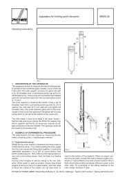
2 FUNCTION ELEMENTS AND OPERATING<br />
ELEMENTS<br />
1 Base plate<br />
With measuring device and supports for a measurement<br />
tube. Clamps in the underside of the base plate<br />
allow two tubes which are not in use to be stored there.<br />
2 Fixing support<br />
For fixing one part of the measurement tube. The support<br />
is attached to the base plate at the 600 mm mark<br />
<strong>with</strong> a milled screw. It can be removed from this position<br />
and be attached to the base plate at the 400 mm<br />
or 200 mm marking.<br />
3 Resting support<br />
Freely supports the end of the measurement tube<br />
which presses against the <strong>clock</strong> <strong>gauge</strong> feeler.<br />
4 Hose clamps<br />
For holding the inlet and outlet hoses transporting<br />
water into and out of the tube.<br />
1<br />
5 Clamping device<br />
For fixing the <strong>clock</strong> <strong>gauge</strong>.<br />
6 Clock <strong>gauge</strong><br />
For measurement of the linear expansion.<br />
<strong>04233.00</strong><br />
7 3 5 6<br />
7 Measurement tubes<br />
With hose nipples for connection of the water inlet and<br />
outlet hoses, and <strong>with</strong> circular grooves for positioning<br />
the tube in the fixing support at the defined 200 mm,<br />
400 mm or 600 mm measurement lengths.<br />
3 HANDLING<br />
The apparatus is supplied <strong>with</strong> the fixing support 3 attached<br />
to the base plate at the 600 mm marking. You must appropriately<br />
change its position for a shorter tube length. To insert<br />
the measurement tube in the dilatometer, first guide it<br />
from the inside through the fixing support and then push the<br />
closed end from the inside through the resting support. For<br />
the correct hold in the fixing support, ensure that the milled<br />
screw exactly catches the circular groove in the tube when<br />
it is tightened, then check that it holds the tube so firmly that<br />
it cannot be moved.<br />
Slide the <strong>clock</strong> <strong>gauge</strong> in the direction of the clamping device<br />
5 until the dial pointer is deflected a little, then fix it in this<br />
position by screwing the clamp tight. Turn the outer ring of<br />
the <strong>clock</strong> <strong>gauge</strong> to move the dial so that the pointer is at the<br />
zero point.<br />
Connect rubber tubing (i.d. = 6 mm) to the two hose nipples<br />
so that the water flows in at the hose nipple at the closed<br />
end and out of the other hose nipple. Fix the tubings in the<br />
hose clamps 4 so that no unintentional force is exerted on<br />
the measurement tube. Control the temperature of the<br />
water <strong>with</strong> a thermostat.<br />
When the glass measurement tube is used, the linear expansion<br />
is so small that the warming up and expansion of<br />
the base plate can cause a noticeable measurement error.<br />
<strong>PHYWE</strong> SYSTEME GMBH · Robert-Bosch-Breite 10 · D-37079 · Göttingen · Telefon (05 51) 6 04-0 ·Telefax (05 51) 60 41 07<br />
7<br />
4
We therefore recommend in this case that the measurement<br />
only be carried out at two temperatures. First carry out<br />
the measurement <strong>with</strong> hot water, then replace the hot water<br />
in the thermostat <strong>with</strong> cold water. With this succession, the<br />
time of temperature change is brief and the temperature of<br />
the base plate remains approximately constant.<br />
4 EXPERIMENT<br />
The thermal expansion is given by:<br />
Δl = α ⋅ l 0 ⋅ Δϑ ,<br />
where Δl is the linear expansion resulting from the temperature<br />
change Δϑ, l o the total length of the tube before heating<br />
it and α the linear expansion coefficient.<br />
Values for α given in the literature:<br />
Brass 18 ⋅ 10 -6 ⋅ K -1<br />
Steel 11...12 ⋅ 10 -6 ⋅ K -1<br />
Duran glass 3,2 ⋅ 10 -6 ⋅ K -1<br />
With measurement tubes made of other materials, available<br />
as accessories, the following linear expansion coefficients<br />
can be determined:<br />
Aluminium 23 ⋅ 10 -6 ⋅ K -1<br />
Copper 17 ⋅ 10 -6 ⋅ K -1<br />
Quartz glass 0,45 ⋅ 10 -6 ⋅ K -1<br />
5 LITERATURE<br />
Laboratory Experiments Physics 16502.12<br />
Exp. Nr. 3.1.01<br />
6 LIST OF EQUIPMENT<br />
Linear expansion apparatus 04231.01<br />
Copper tube 04231.05<br />
Aluminium tube 04231.06<br />
Quartz tube 04231.07<br />
Rubber tubing, i.d. = 6 mm (2x) 39282.00<br />
Immersion thermostat 46994.93<br />
Cooling coil 46994.01<br />
Set of accessories for immersion thermostat 46994.02<br />
Bath for thermostat, Makrolon 08487.02<br />
Replacement material for 04231.01:<br />
Brass tube 04231.02<br />
Iron tube 04231.03<br />
Glass tube 04231.04<br />
7 NOTE ON THE GUARANTEE<br />
We guarantee the instrument supplied by us for a period of<br />
6 months. This guarantee does not cover natural wear nor<br />
damage resulting from improper handling.<br />
The manufacturer can only be held responsible for the function<br />
and safety characteristics of the instrument, when<br />
maintenance, repairs and changes to the instrument are<br />
only carried out by the manufacturer or by personnel who<br />
have been explicitly authorized by him to do so.<br />
2 <strong>04233.00</strong>