CADD-Legacy® PCA - Smiths Medical
CADD-Legacy® PCA - Smiths Medical
CADD-Legacy® PCA - Smiths Medical

You also want an ePaper? Increase the reach of your titles
YUMPU automatically turns print PDFs into web optimized ePapers that Google loves.
Legacy<br />
Operator’s Manual<br />
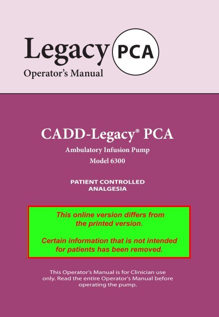
<strong>CADD</strong>-Legacy ® <strong>PCA</strong><br />
Ambulatory Infusion Pump<br />
Model 6300<br />
<strong>PCA</strong><br />
PATIENT CONTROLLED<br />
ANALGESIA<br />
This Operator’s Manual is for Clinician use<br />
only. Read the entire Operator’s Manual before<br />
operating the pump.
This manual pertains only to the <strong>CADD</strong>-<strong>Legacy®</strong> <strong>PCA</strong> (Patient Controlled<br />
Analgesia) Model 6300 ambulatory infusion pump. There are other <strong>CADD</strong>-<br />
<strong>Legacy®</strong> pump models available; review the rear label of the pump to ensure<br />
it is a <strong>CADD</strong>-<strong>Legacy®</strong> <strong>PCA</strong> Model 6300 pump before programming. This<br />
pump delivers medication at a constant rate and/or allows delivery of a bolus<br />
dose at a specified time interval.<br />
This manual is intended for clinician use only. Do not permit patients<br />
to have access to this manual. The pump has 3 security levels designed<br />
to limit patient access. Do not disclose the pump’s security codes or any<br />
other information that would allow inappropriate access to programming<br />
and operating functions.<br />
The issue date of this Operator’s Manual is included on the back cover for<br />
the clinician’s information. In the event one year has elapsed between the<br />
issue date and product use, the clinician should contact <strong>Smiths</strong> <strong>Medical</strong><br />
MD, Inc. to see if a later revision of this manual is available.<br />
Technical Assistance<br />
If you have comments or questions concerning the operation of the <strong>CADD</strong>-<br />
<strong>Legacy®</strong> pump, please call the appropriate number given below. When calling,<br />
please specify your pump’s software module. This information is located<br />
on the start-up screen.<br />
Our staff at <strong>Smiths</strong> <strong>Medical</strong> MD, Inc. is available to help clinicians 24<br />
hours a day with the programming and operation of the <strong>CADD</strong>-<strong>Legacy®</strong><br />
infusion system.<br />
U.S. Distribution European Representative<br />
<strong>Smiths</strong> <strong>Medical</strong> MD, Inc. <strong>Smiths</strong> <strong>Medical</strong> International Ltd.<br />
1265 Grey Fox Road WD24 4LG UK<br />
St. Paul, MN 55112 USA +44 (0)1923 246434<br />
1 800.426.2448 (USA)<br />
+1 651.633.2556<br />
ii
Read this entire Operator’s Manual before operating the <strong>CADD</strong>-<strong>Legacy®</strong><br />
ambulatory infusion pump.<br />
Failure to properly follow warnings, cautions, and instructions could<br />
result in death or serious injury to the patient.<br />
Warnings<br />
• This Operator’s Manual should be used by clinicians only. Do not<br />
permit patients to have access to this manual, as the information<br />
contained would allow the patient complete access to all programming<br />
and operating functions. Improper programming could result<br />
in death or serious injury to the patient.<br />
• To avoid explosion hazard, do not use the pump in the presence of<br />
flammable anesthetics or explosive gases.<br />
• For those patients who are likely to be adversely affected by unintended<br />
operations and failures, including interrupted medication or fluid<br />
delivery from the device, close supervision and provision for immediate<br />
corrective action should be provided.<br />
• If the pump is used to deliver life-sustaining medication, a backup<br />
pump should be available.<br />
• The pump should not to be used for delivery of blood or cellular blood<br />
products.<br />
• If the pump is dropped or hit, inspect the pump for damage. Do not<br />
use a pump that is damaged or is not functioning properly. Contact<br />
<strong>Smiths</strong> <strong>Medical</strong> MD, Inc. Customer Service to return a pump for<br />
service.<br />
• Use of a syringe with the <strong>CADD</strong> Administration Set may result in<br />
UNDER-DELIVERY of medication. Syringe function can be adversely<br />
affected by variations in plunger dimension and lubricity, which can<br />
result in greater force required to move the syringe plunger. A syringe<br />
plunger will lose lubrication as it ages and, as a result, the amount of<br />
under-delivery will increase which could on occasion, be significant.<br />
Therefore, the type of medication and delivery accuracy required<br />
must be considered when using a syringe with the <strong>CADD</strong>® pump.<br />
iii
iv<br />
Clinicians must regularly compare the volume remaining in the syringe<br />
to the pump’s displayed values such as RES VOL and GIVEN in<br />
order to determine whether under-delivery of medication is occurring<br />
and if necessary, take appropriate action.<br />
• System delivery inaccuracies may occur as a result of back pressure or<br />
fluid resistance, which depends upon medication viscosity, catheter size,<br />
and extension set tubing (for example, microbore tubing).<br />
• Do not administer medications to the epidural space or subarachnoid<br />
space unless the medication is indicated for administration to those<br />
spaces.<br />
• To prevent infusion of medications that are not indicated for epidural<br />
space or subarachnoid space infusion, do not use administration sets<br />
that incorporate injection sites.<br />
• If a Medication Cassette Reservoir, <strong>CADD</strong> Extension Set or <strong>CADD</strong><br />
Administration Set is used for medication delivery into the epidural<br />
or subarachnoid space, clearly differentiate them from those used for<br />
other routes of infusion, for example, by color coding, or other means<br />
of identification.<br />
• When the Air Detector is turned off, the pump will not detect air in<br />
the fluid path. Periodically inspect the fluid path and remove any air<br />
to prevent air embolism.<br />
• Follow the Instructions for Use provided with the Medication Cassette<br />
Reservoir and <strong>CADD</strong> Extension Set, or <strong>CADD</strong> Administration<br />
Set, paying particular attention to all warnings and cautions<br />
associated with their use.<br />
• When the Upstream Occlusion Sensor is turned off, the pump will not<br />
detect occlusions upstream (between pump and fluid container). Periodically<br />
inspect the fluid container for decreasing volume, inspect the fluid<br />
path for kinks, a closed clamp, or other upstream occlusions. Upstream<br />
occlusions could result in under- or non-delivery of medications.<br />
• Do not disclose to the patient the pump’s security codes or any other<br />
information that would allow the patient complete access to all programming<br />
and operating functions.
• Do not use rechargeable NiCad or nickel metal hydride (NiMH) batteries.<br />
Do not use carbon zinc (“heavy duty”) batteries. They do not<br />
provide sufficient power for the pump to operate properly.<br />
• Always have new batteries available for replacement. If power is lost,<br />
non-delivery of medication will occur.<br />
• If the pump is dropped or hit, the battery door or tabs may break. Do<br />
not use the pump if the battery door or tabs are damaged because the<br />
batteries will not be properly secured; this may result in loss of power<br />
and non-delivery of medication.<br />
• If a gap is present anywhere between the battery door and the pump<br />
housing, the door is not properly latched. If the battery door becomes<br />
detached or loose, the batteries will not be properly secured; this<br />
could result in loss of power and non-delivery of medication.<br />
• Ensure that the ± 6% System Delivery Accuracy specification is taken<br />
into account when programming the pump and/or filling the Medication<br />
Cassette Reservoir. Failure to do so may result in medication in<br />
the reservoir becoming depleted sooner than expected.<br />
• This pump delivers medication at a constant rate and/or allows delivery<br />
of a bolus dose at a specified time interval. Programming the<br />
pump at a delivery rate other than what is prescribed will cause over<br />
or under delivery of medication.<br />
• When you enter a new Dose Lockout time or Doses per Hour value,<br />
any lockout time in effect will be cleared. A Demand Dose could be<br />
requested and delivered immediately upon starting the pump, resulting<br />
in over-delivery of medication.<br />
• Close the fluid path tubing with the clamp before removing the cassette<br />
from the pump to prevent unregulated gravity infusion.<br />
• For detailed instructions and warnings pertaining to Medication<br />
Cassette Reservoir or <strong>CADD</strong> Administration Sets, please refer to the<br />
instructions supplied with those products.<br />
v
• Attach the cassette (the part of the Medication Cassette Reservoir or<br />
<strong>CADD</strong> Administration Set that attaches to the pump) properly. An<br />
improperly attached or detached cassette could result in unregulated<br />
gravity infusion of medication from the fluid container or a reflux of<br />
blood.<br />
vi<br />
If you are using a <strong>CADD</strong> Administration Set or Medication Cassette<br />
Reservoir that does not have the flow stop feature (catalog number does<br />
not start with 21-73xx): You must use a <strong>CADD</strong> Extension Set with an<br />
integral Anti-Siphon Valve or a <strong>CADD</strong> Administration Set with either<br />
an integral or Add On Anti-Siphon Valve to protect against unregulated<br />
gravity infusion that can result from an improperly attached cassette.<br />
• Do not prime the fluid path with the tubing connected to a patient as<br />
this could result in overdelivery of medication or air embolism.<br />
• Ensure that the entire fluid path is free of all air bubbles before connecting<br />
to the patient to prevent air embolism.<br />
• Prior to starting infusion, inspect the fluid path for kinks, a closed<br />
clamp, or other upstream occlusions, and remove any air to prevent<br />
air embolism.<br />
• Exercise care when using the Clinician Bolus function. Since there are<br />
no limits on the frequency of delivering a bolus, and since the amount<br />
of bolus can be set as high as 20 ml (or the mg or mcg equivalent), you<br />
should not permit the patient to become familiar with the procedure<br />
for giving a Clinician Bolus.<br />
• To prevent the patient from accessing the Clinician Bolus function, do<br />
not let the patient know the Clinician Bolus security code.<br />
• The use of Power Supplies and a Remote Dose Cord other than those<br />
listed in the Electromagnetic emissions declaration may result in<br />
increased emissions or decreased immunity of the Pump.<br />
• The Pump should not be used adjacent to or stacked with other equipment.<br />
If adjacent or stacked use is necessary, the user should verify normal operation<br />
of the pump in the configuration in which it is to be used.
• There are potential health hazards associated with improper disposal of<br />
batteries, electronics, and contaminated (used) reservoirs and extension<br />
sets. Dispose of used batteries, reservoirs, extension sets and other used<br />
accessories, or a pump that has reached the end of its useful life, in an environmentally<br />
safe manner, and according to any regulations that may apply.<br />
Cautions<br />
• Do not operate the pump at temperatures below +2°C (36°F) or above<br />
40°C (104°F).<br />
• Do not store the pump at temperatures below -20°C (-4°F) or above<br />
60°C (140°F). Do not store the pump with the Medication Cassette<br />
Reservoir or <strong>CADD</strong> Administration Set attached. Use the Protective<br />
Cassette provided.<br />
• Do not expose the pump to humidity levels below 20% or above 90%<br />
relative humidity.<br />
• Do not store the pump for prolonged periods of time with the batteries<br />
installed.<br />
• Frozen medication must be thawed at room temperature only. Do not<br />
heat the Medication Cassette Reservoir in a microwave oven as this<br />
may damage the medication, the Medication Cassette Reservoir, or<br />
cause leakage.<br />
• Do not immerse the pump in cleaning fluid or water or allow solution<br />
to soak into the pump, accumulate on the keypad, or enter the battery<br />
compartment.<br />
• Do not clean the pump with acetone, other plastic solvents, or abrasive<br />
cleaners, as damage to the pump may occur.<br />
• Do not expose the pump to therapeutic levels of ionizing radiation<br />
as permanent damage to the pump’s electronic circuitry may occur.<br />
The best procedure to follow is to remove the pump from the patient<br />
during therapeutic radiation sessions. If the pump must remain in the<br />
vicinity during a therapy session, it should be shielded, and its ability<br />
to function properly should be confirmed following treatment.<br />
vii
• Do not expose the pump directly to ultrasound, as permanent damage<br />
to the pump’s electronic circuitry may occur.<br />
• Do not use the pump in the vicinity of magnetic resonance imaging<br />
(MRI) equipment as magnetic fields may adversely affect the operation<br />
of the pump. Remove the pump from the patient during MRI procedures<br />
and keep it at a safe distance from magnetic energy.<br />
• Do not use the pump near ECG equipment as the pump may interfere<br />
with the operation of the equipment. Monitor ECG equipment carefully<br />
when using this pump.<br />
• Do not sterilize the pump.<br />
• Use only <strong>Smiths</strong> <strong>Medical</strong> MD, Inc. accessories as using other brands<br />
may adversely affect the operation of the pump.<br />
• <strong>CADD</strong>-<strong>Legacy®</strong> pumps are sealed units. A broken or damaged seal<br />
will, therefore, be considered conclusive evidence that the pump has<br />
been misused and/or altered, which voids any and all warranties. All<br />
service and repair of <strong>CADD</strong>-<strong>Legacy®</strong> pumps must be performed by<br />
<strong>Smiths</strong> <strong>Medical</strong> MD, Inc. or its authorized agents.<br />
• Check appropriate medication stability for time and temperature to<br />
assure stability with actual pump delivery conditions.<br />
• Information regarding the recommended Medication Cassette Reservoirs,<br />
<strong>CADD</strong> Extension Sets, <strong>CADD</strong> Administration Sets and accessories<br />
is available in the Product List that accompanies the <strong>CADD</strong>-<br />
<strong>Legacy®</strong> pump.<br />
viii
Table of Contents<br />
Warnings iii<br />
Cautions vii<br />
1.0 General Description 1<br />
Introduction ........................................................................................................1<br />
Indications ...........................................................................................................1<br />
Epidural/Subarachnoid Administration .........................................................1<br />
Symbols ................................................................................................................3<br />
Pump Diagram ...................................................................................................4<br />
Description of the Keys, Display, and Features ............................................5<br />
The Main Screen .................................................................................................8<br />
Lock Levels ..........................................................................................................9<br />
Security Codes ....................................................................................................9<br />
Lock Level Table ...............................................................................................10<br />
2.0 Pump Setup and Programming 11<br />
Installing or Replacing the Batteries .............................................................11<br />
Watching Power Up .........................................................................................16<br />
Changing to Lock Level 0 (LL0) ....................................................................17<br />
Programming the Pump: General Instructions ..........................................18<br />
Delivery Methods .............................................................................................19<br />
Programming Screens for <strong>PCA</strong> Delivery .................................................... 20<br />
Programming <strong>PCA</strong> Delivery ......................................................................... 24<br />
Removing a Cassette ........................................................................................29<br />
Attaching a Cassette ....................................................................................... 30<br />
Priming the Tubing (Using the Pump)<br />
and Connecting to the Patient ....................................................................32<br />
Inserting the Tubing into the Air Detector ................................................. 34<br />
Setting the Lock Level for the Patient ...........................................................36<br />
Programming with Upper Limits, Adjusting Doses in Lock Level 1 .......37<br />
ix
3.0 Operating the Pump 39<br />
Starting the Pump ............................................................................................39<br />
Stopping the Pump ..........................................................................................39<br />
Turning the Pump On/Off ............................................................................. 40<br />
Starting a Clinician Bolus ...............................................................................41<br />
Starting a Demand Dose ................................................................................ 42<br />
Stopping a Demand Dose or Clinician Bolus ............................................. 42<br />
Resetting the Reservoir Volume ................................................................... 43<br />
4.0 Biomed Functions 45<br />
Overview: Accessing the Biomed Functions ............................................... 45<br />
Air Detector On/Off ....................................................................................... 46<br />
Upstream Occlusion Sensor On/Off..............................................................47<br />
5.0 Reference 49<br />
Messages and Alarms, Alphabetical List ......................................................49<br />
Cleaning the Pump and Accessories .............................................................53<br />
Exposure to Radiation, Ultrasound, Magnetic Resonance Imaging<br />
(MRI), or Use near ECG Equipment .........................................................55<br />
Continuous Rate Scroll Ranges ..................................................................... 56<br />
Demand Dose, Clinician Bolus Scroll Ranges: Milliliters ........................ 56<br />
Demand Dose, Clinician Bolus Scroll Ranges: Milligrams .......................57<br />
Demand Dose, Clinician Bolus Scroll Ranges: Micrograms .....................58<br />
Technical Description......................................................................................59<br />
Specifications (Nominal) ............................................................................ 60<br />
Accuracy Test Results ..................................................................................65<br />
Electromagnetic Emissions and Immunity Declarations .......................67<br />
Safety Features and Fault Detection ..........................................................71<br />
Software Safety Features ..............................................................................73<br />
Data Handling Software Safety Features ..................................................74<br />
Annual Functional Inspection and Testing Procedures .........................75<br />
Inspection Procedures .................................................................................75<br />
Testing Procedures .......................................................................................76<br />
Occlusion Pressure Range Tests .................................................................82<br />
Accuracy Tests ..............................................................................................85<br />
Index ................................................................................................................. 90<br />
Limited Warranty ............................................................................................92<br />
x
1.0 General Description<br />
Introduction<br />
Section 1: General Description<br />
The <strong>CADD</strong>-<strong>Legacy®</strong> <strong>PCA</strong> (Patient Controlled Analgesia) ambulatory<br />
infusion pump provides measured medication therapy to patients in<br />
hospital or outpatient settings. Therapy should always be overseen by a<br />
physician or a certified, licensed healthcare professional. As appropriate<br />
to the situation, the patient should be instructed in using and troubleshooting<br />
the pump.<br />
Indications<br />
The <strong>CADD</strong>-<strong>Legacy®</strong> <strong>PCA</strong> pump is indicated for intravenous, intra-arterial,<br />
subcutaneous, intraperitoneal, epidural space, or subarachnoid<br />
space infusion. The pump is intended for therapies that require a continuous<br />
rate of infusion, patient-controlled demand doses, or both (such<br />
as patient-controlled analgesia).<br />
Epidural/Subarachnoid Administration<br />
The selected medication must be used in accordance with the indications<br />
included in the package insert accompanying the medication. Administration<br />
of any medication by this pump is limited by any warnings,<br />
precautions, or contraindications in the medication labeling.<br />
Analgesics<br />
Administration of analgesics to the epidural space is limited to use with<br />
indwelling catheters specifically indicated for either short-or long-term<br />
medication delivery.<br />
Administration of analgesics to the subarachnoid space is limited to use<br />
with indwelling catheters specifically indicated for short-term medication<br />
delivery.<br />
Anesthetics<br />
Administration of anesthetics to the epidural space is limited to use with<br />
indwelling catheters specifically indicated for short-term medication<br />
delivery.<br />
General<br />
Description
General<br />
Description<br />
Section 1: General Description<br />
WARNING:<br />
• Do not administer medications to the epidural space or subarachnoid<br />
space unless the medication is indicated for administration to<br />
those spaces. Medications not intended for epidural or subarachnoid<br />
space infusion could result in death or serious injury to the<br />
patient.<br />
• To prevent the infusion of medications that are not indicated for<br />
epidural space or subarachnoid space infusion, do not use administration<br />
sets that incorporate injection sites. The inadvertent use<br />
of injection sites for infusion of such medications could result in<br />
death or serious injury to the patient.<br />
• If a Medication Cassette Reservoir, <strong>CADD</strong> Extension Set or<br />
<strong>CADD</strong> Administration Set is used for medication delivery into<br />
the epidural or subarachnoid space, clearly differentiate them from<br />
those used for other routes of infusion, for example, by color coding,<br />
or other means of identification. Medications not intended for<br />
epidural or subarachnoid space infusion could result in death or<br />
serious injury to the patient.
Symbols<br />
O<br />
Direct Current (Power Jack)<br />
Accessory Jack<br />
f Attention, see Instructions for Use<br />
K Class II Equipment<br />
Type CF Equipment<br />
Section 1: General Description<br />
E Splashproof - water splashed against pump housing will have no<br />
harmful effects (see Cleaning the Pump and Accessories, Section<br />
5, for additional important information)<br />
D Date of Manufacture<br />
< Catalog (reorder) number<br />
> Serial Number<br />
Z Collect Separately<br />
@ Authorized Representative in the European Community<br />
General<br />
Description
General<br />
Description<br />
Section 1: General Description<br />
Pump Diagram<br />
Display<br />
Power Jack<br />
Accessory Jack<br />
AC Indicator<br />
Light<br />
Air Detector<br />
Keypad<br />
Cassette<br />
Threaded<br />
Mounting Hole<br />
Battery<br />
Compartment<br />
Cassette Lock<br />
®<br />
Front<br />
View<br />
Power Jack<br />
symbol<br />
Accessory<br />
Jack symbol<br />
Rear<br />
View
Section 1: General Description<br />
Description of the Keys, Display, and Features<br />
AC Indicator Light<br />
The green indicator light is on when you are using the AC adapter to<br />
power pump.<br />
Display<br />
The Liquid Crystal Display (LCD) shows programming information and<br />
messages. In this manual, the term “display” is synonymous with display<br />
panel or LCD.<br />
Keypad<br />
The keys on the keypad are described below. A key beeps when pressed if<br />
it is operable in the current lock level.<br />
⁄ used to start and stop pump delivery, and silence alarms.<br />
¤ used to enter (save) a new value in the pump’s memory when<br />
programming pump settings or to clear values from record-keeping<br />
screens. It is also used to return from the Biomed Functions<br />
to the main screen (Section 4).<br />
‹ used to fill the tubing and to remove air bubbles from the fluid path.<br />
Œ used to view or change the pump’s current lock level. Lock levels<br />
are used to limit patient access to certain programming and operating<br />
functions. (See Lock Levels, this section.)<br />
„ used to move from one programming screen to the next without<br />
changing the setting or value displayed; silences alarms.<br />
´ used to “scroll up” or increase a value, or scroll through Biomed<br />
Function settings.<br />
Î used to “scroll down” or decrease a value, or scroll through<br />
Biomed Function settings.<br />
Å used to put the pump into a low power state when not in use or<br />
back into full power.<br />
General<br />
Description
General<br />
Description<br />
Section 1: General Description<br />
Í used in the <strong>PCA</strong> delivery mode. It allows the patient to deliver a<br />
programmed amount of medication upon request.<br />
Power Jack<br />
You may plug an AC Adapter into the Power Jack as an alternate source<br />
of power. The indicator light on the front of the pump will illuminate<br />
when the AC Adapter is in use.<br />
Accessory Jack<br />
The accessory jack is used for attaching a Remote Dose Cord for remote<br />
operation of the dose key and for accessory cables. See the Instructions<br />
for Use supplied with those accessories.<br />
Air Detector<br />
The Air Detector is on the pump in the area shown in the diagram. If air<br />
is detected in the part of the tubing that passes through the Air Detector,<br />
an alarm sounds and delivery stops. (See Section 5 for Air Detector<br />
specifications.) If an Air Detector is not required, it may be turned off.<br />
(See Section 4, Biomed Functions.)<br />
WARNING: When the Air Detector is turned off, the pump will not<br />
detect air in the fluid path. Periodically inspect the fluid path and<br />
remove any air to prevent air embolism. Air embolism could result in<br />
death or serious injury to the patient.<br />
Cassette<br />
The cassette is the part of the <strong>CADD</strong> Medication Cassette Reservoir or<br />
<strong>CADD</strong> Administration Set that attaches to the bottom of the pump.<br />
The following single-use products are compatible with the <strong>CADD</strong>-<strong>Legacy®</strong><br />
pump:<br />
• <strong>CADD</strong> Medication Cassette Reservoir (50 or 100 ml), used with the<br />
<strong>CADD</strong> Extension Set<br />
• <strong>CADD</strong> Administration Set
Section 1: General Description<br />
WARNING: Follow the Instructions for Use provided with the Medication<br />
Cassette Reservoir and <strong>CADD</strong> Extension Set, or <strong>CADD</strong><br />
Administration Set, paying particular attention to all warnings and<br />
cautions associated with their use. Incorrect preparation and/or use of<br />
these products could result in serious patient injury or death.<br />
Threaded Mounting Hole<br />
The optional Polemount Bracket Adapter attaches to the threaded mounting<br />
hole in the back of the pump, allowing you to hang the pump on an IV pole.<br />
Battery Compartment<br />
Two AA batteries fit into the battery compartment. The AA batteries serve as<br />
the primary source of power, or as a backup when an AC Adapter is in use.<br />
Cassette Lock<br />
This attaches the cassette (the part of the Medication Cassette Reservoir<br />
or <strong>CADD</strong> Administration Set that attaches to the pump) to the pump.<br />
This allows you to secure the cassette to the pump using the key provided.<br />
If the cassette becomes unlocked while the pump is running, delivery<br />
will stop and an alarm will occur. If the cassette becomes unlocked while<br />
the pump is stopped, an alarm will occur.<br />
Other Features Not Shown<br />
Upstream Occlusion Sensor: The pump contains an upstream occlusion<br />
sensor. This feature may be turned on or off (see Section 4, Biomed<br />
Functions). When the sensor is turned on, and an upstream occlusion<br />
(between pump and fluid container) is detected, an alarm will sound,<br />
delivery will stop, and the display will show “Upstream Occlusion.”<br />
WARNING: When the Upstream Occlusion Sensor is turned off, the<br />
pump will not detect occlusions upstream (between pump and fluid<br />
container). Periodically inspect the fluid container for decreasing<br />
volume, inspect the fluid path for kinks, a closed clamp, or other upstream<br />
occlusions. Upstream occlusions could result in under- or nondelivery<br />
of medications. If undetected, these occlusions could result in<br />
death or serious injury to the patient.<br />
General<br />
Description
General<br />
Description<br />
Section 1: General Description<br />
Downstream Occlusion Sensor: The pump contains a downstream occlusion<br />
sensor. When a downstream occlusion (between the pump and<br />
patient access site) is detected, an alarm will sound, delivery will stop,<br />
and the display will show “High Pressure”.<br />
Reservoir Volume Alarm: The Reservoir Volume Alarm indicates when<br />
the fluid in the fluid container is low or depleted. Each time you change<br />
the fluid container, you may reset the Reservoir Volume to the originally<br />
programmed volume. Then, as medication is delivered, the Reservoir<br />
Volume automatically decreases. When the pump calculates that 5 ml<br />
remain in the fluid container, beeps sound and “ResVol Low” appears on<br />
the main screen. This alarm recurs at every subsequent decrease of 1 ml<br />
until the Reservoir Volume reaches 0 ml, at which point the pump stops<br />
and the Reservoir Volume empty alarm sounds.<br />
The Main Screen<br />
The main screen is the starting point for programming or viewing the<br />
pump’s settings.<br />
If no keys are pressed for a period of time (2 minutes), the display reverts<br />
to the main screen. When the two AA batteries are low, “LowBat” appears<br />
on the main screen.<br />
When running:<br />
Status of pump<br />
Reservoir Volume<br />
When stopped:<br />
Status of pump<br />
RUN LowBat<br />
ResVol 50.0 ml<br />
STOPPED<br />
Battery Status<br />
Status of Reservoir<br />
Volume
Lock Levels<br />
Section 1: General Description<br />
Lock levels are used to limit patient access to certain programming and<br />
operating functions. The table on the next page lists the functions that<br />
are accessible in Lock Level 0 (LL0), Lock Level 1 (LL1), and Lock Level 2<br />
(LL2). When a function is accessible, the key associated with the function<br />
beeps when pressed. If a function is not accessible, the pump ignores the<br />
key press and a beep does not sound. Section 2, Pump Setup and Programming,<br />
describes how to change the lock level.<br />
Security Codes<br />
The following security codes are preset by the manufacturer for the<br />
clinician’s use:<br />
** Text Omitted from Online Version **<br />
WARNING: Do not disclose to the patient the pump’s security<br />
codes or any other information that would allow the patient complete<br />
access to all programming and operating functions. Improper<br />
programming could result in death or serious injury to the patient.<br />
General<br />
Description
General<br />
Description<br />
Section 1: General Description<br />
Lock Level Table<br />
This table lists the operations that are accessible in each lock level while<br />
the pump is stopped and running. LL0 permits complete access to all<br />
programming and operating functions. LL1 permits limited control of<br />
pump programming and operations. LL2 permits only minimal control<br />
of pump operations.<br />
Pump Operations and Programming<br />
0<br />
Stopped Running<br />
LL0 LL1 LL2<br />
Any Lock<br />
Level<br />
Stop/Start the pump Yes Yes Yes Yes<br />
Reset Reservoir Volume Yes Yes Yes No<br />
Prime Yes Yes No No<br />
Change the Lock Level<br />
Yes,<br />
w/code<br />
Yes,<br />
w/code<br />
Yes,<br />
w/code<br />
Start a Demand Dose No No No Yes<br />
Start a Clinician Bolus No No No Yes<br />
Change Units Yes No No No<br />
Change Concentration Yes No No No<br />
Change Continuous Rate Yes<br />
Change Demand Dose Yes<br />
Up to LL0<br />
value<br />
Up to LL0<br />
value<br />
No<br />
No No<br />
No No<br />
Clear Doses Given Yes Yes No No<br />
Clear Doses Attempted Yes Yes No No<br />
Clear Given amount Yes Yes No No<br />
Biomed Functions<br />
Access to Functions<br />
Air Detector On/Off<br />
Upstream Occlusion Sensor<br />
On/Off<br />
Yes,<br />
w/code No No No<br />
Yes,<br />
w/code<br />
Yes,<br />
w/code<br />
View Only View Only View Only<br />
View Only View Only View Only
2.0 Pump Setup and Programming<br />
Installing or Replacing the Batteries<br />
Section 2: Pump Setup and Programming<br />
Use new, AA (IEC LR6) alkaline batteries such as DURACELL® or<br />
EVEREADY® ENERGIZER® batteries. The pump retains all programmed<br />
values while the batteries are removed. Some of the programmed values<br />
are retained in RAM memory that is supported by an internal battery for<br />
5 years from date of manufacture.<br />
Dispose of used batteries in an environmentally safe manner, and according<br />
to any regulations which may apply.<br />
WARNING:<br />
• Do not use rechargeable NiCad or nickel metal hydride (NiMH)<br />
batteries. Do not use carbon zinc (“heavy duty”) batteries. They<br />
do not provide sufficient power for the pump to operate properly,<br />
which could result in death or serious injury to the patient.<br />
• Always have new batteries available for replacement. If power is<br />
lost, non-delivery of medication will occur and, depending on the<br />
type of medication being administered, could result in death or<br />
serious injury to the patient.<br />
• If the pump is dropped or hit, the battery door or tabs may break.<br />
Do not use the pump if the battery door or tabs are damaged because<br />
the batteries will not be properly secured; this may result in<br />
loss of power, non-delivery of medication, and, depending on the<br />
type of medication being administered, death or serious injury to<br />
the patient.<br />
Pump Setup &<br />
Programming
Pump Setup &<br />
Programming<br />
Section 2: Pump Setup and Programming<br />
In order to install or replace the batteries, be sure the pump is Stopped.<br />
Then, follow these steps:<br />
1. Push down and hold the arrow button while sliding the door off.<br />
2. Remove the used batteries. Pulling on the end of the battery strap<br />
will make battery removal easier.<br />
3. Install the new batteries in the compartment, making sure the battery<br />
strap is positioned correctly under the batteries.<br />
NOTE:<br />
• Be sure to match the polarity markings of the new batteries (+ and<br />
–) with those labeled in the battery compartment. If you put the<br />
batteries in backwards, the display panel will be blank, and you<br />
will not hear a beep.<br />
• Use 2 new, AA (IEC LR6) alkaline batteries to power the pump.<br />
You may use any alkaline batteries, including DURACELL®<br />
Alkaline and EVEREADY® ENERGIZER® Alkaline, for example.
Section 2: Pump Setup and Programming<br />
4. Place the battery door over the battery compartment and slide the<br />
door closed.<br />
5. Ensure that the door is latched by trying to remove the door without<br />
pressing the arrow button.<br />
NOTE: The power-up sequence will start, the pump will go through<br />
an electronic self-test, and the pump will beep 6 times at the end of<br />
the power-up sequence. All of the display indicators, the software<br />
revision level, and each parameter will appear briefly.<br />
Pump Setup &<br />
Programming
Pump Setup &<br />
Programming<br />
Section 2: Pump Setup and Programming<br />
WARNING: If a gap is present anywhere between the battery<br />
door and the pump housing, the door is not properly latched.<br />
If the battery door becomes detached or loose, the batteries<br />
will not be properly secured; this could result in loss of power,<br />
non-delivery of medication, and, depending on the type of<br />
medication being administered, death or serious injury to the<br />
patient.
Section 2: Pump Setup and Programming<br />
6. Resume operation of the current program by pressing and holding<br />
⁄ to start the pump or proceed to program the pump.<br />
NOTE:<br />
• The life of the batteries is dependent on the amount of medication<br />
delivered, delivery rate, battery age, and the temperature.<br />
• At the rate of one 50 ml Medication Cassette Reservoir per day,<br />
alkaline batteries will usually last about 7 days.<br />
• The power of the batteries will be quickly depleted at temperatures<br />
below +10°C (50°F).<br />
CAUTION: Do not store the pump for prolonged periods<br />
of time with the batteries installed. Battery leakage could<br />
damage the pump.<br />
Pump Setup &<br />
Programming
Pump Setup &<br />
Programming<br />
Section 2: Pump Setup and Programming<br />
Watching Power Up<br />
When you install the batteries, the pump will start its power up sequence<br />
during which it performs self-tests and displays programmed values.<br />
Watch for the following:<br />
• Pump model number and serial number appear unless an error has<br />
occurred, then the last error code (“LEC”) if any, will appear.<br />
• The software version will appear.<br />
• The display will turn on, showing a series of blocks. Look for any<br />
blank areas, which would indicate a faulty display.<br />
• The display will turn off briefly.<br />
• The pump’s program screens will appear, followed by screens showing<br />
the Air Detector status, Upstream Occlusion sensor status, and lock<br />
level setting. The pump will beep after each screen. If messages appear,<br />
see the Messages and Alarms Table in Section 5 of this manual<br />
for further explanation and instruction.<br />
• When power up is complete, 6 beeps will sound, and the pump will be<br />
stopped on the main screen.<br />
NOTE: To move quickly through the power-up screens, press „<br />
repeatedly. To skip the automatic review entirely, press Î. If you<br />
attempt to skip screens before the pump is powered up, it will not respond.
Changing to Lock Level 0 (LL0)<br />
Section 2: Pump Setup and Programming<br />
Before programming the pump, make sure the pump is set to LL0. LL0<br />
allows the clinician to access all programming and operating functions.<br />
1. Make sure the pump is stopped. Press Œ. The current lock level<br />
will appear. (If the lock level is already LL0, press „ to exit.)<br />
2. Press ´ or Î until “LL0” appears.<br />
3. Press Œ again or ¤. “Code 0” will appear.<br />
4. Press ´ or Î until ** Text Omitted **<br />
WARNING: Do not disclose to the patient the pump’s security<br />
codes or any other information that would allow the patient<br />
complete access to all programming and operating functions.<br />
Improper programming could result in death or serious injury<br />
to the patient.<br />
5. Press Œ or ¤ to set the new lock level.<br />
Pump Setup &<br />
Programming
Pump Setup &<br />
Programming<br />
Section 2: Pump Setup and Programming<br />
Programming the Pump: General Instructions<br />
The procedure for changing a programmed setting is similar for most<br />
programming screens.<br />
WARNING: Ensure that the ± 6% System Delivery Accuracy specification<br />
is taken into account when programming the pump and/or filling<br />
the Medication Cassette Reservoir. Failure to do so may result in<br />
medication in the reservoir becoming depleted sooner than expected.<br />
If the pump is being used to deliver critical or life sustaining medication,<br />
the interruption in the delivery of medication could result in<br />
patient injury or death.<br />
• Make sure the pump is stopped and in Lock Level 0.<br />
• To begin programming, start at the main screen and press „.<br />
• To change a setting, press ´ or Î until the desired setting appears.<br />
(Press and hold these keys to change values with increasing<br />
speed.)<br />
• Press ¤ within 25 seconds to confirm a change or the screen will<br />
revert to the previous setting.<br />
• If any key other than ¤ is pressed, “Value not saved” will appear.<br />
Press „ to return to the screen being programmed, scroll to the<br />
desired value, and press ¤.<br />
• Press „ to advance to the next screen.<br />
• To leave a setting unchanged, press „ to go to the next screen.
Delivery Methods<br />
Section 2: Pump Setup and Programming<br />
WARNING: This pump delivers medication at a constant rate and/or allows<br />
delivery of a bolus dose at a specified time interval. Programming<br />
the pump at a delivery rate other than what is prescribed will cause over<br />
or under delivery of medication, which could result in patient injury or<br />
death.<br />
The <strong>CADD</strong>-<strong>Legacy®</strong> <strong>PCA</strong> pump offers 3 methods of delivery alone or in<br />
combination:<br />
• Continuous Rate (up to 50 ml per hour)<br />
• Demand Dose<br />
• Clinician Bolus<br />
The following graph illustrates the combined delivery methods. The Continuous<br />
Rate and Demand Dose are programmed as described in this<br />
section. The Clinician Bolus feature is described in Section 3, Operating<br />
the Pump. Ranges and programming increments are listed in the Specifications<br />
in Section 5.<br />
Dosage<br />
Clinician Bolus<br />
(used here as a<br />
loading dose)<br />
Demand Doses<br />
Time<br />
Continuous Rate<br />
Pump Setup &<br />
Programming
Pump Setup &<br />
Programming<br />
Section 2: Pump Setup and Programming<br />
Programming Screens for <strong>PCA</strong> Delivery<br />
These are the programming screens for the <strong>CADD</strong>-<strong>Legacy®</strong> <strong>PCA</strong> pump.<br />
Descriptions of the screens follow.<br />
0<br />
Reservoir Volume<br />
Units (ml, mg, or mcg)<br />
Concentration<br />
(mg/ml or mcg/ml)<br />
Continuous Rate<br />
(ml/hr, mg/hr or mcg/hr)<br />
Demand Dose<br />
(ml, mg, or mcg)<br />
Dose Lockout<br />
Doses per Hour<br />
Doses Given<br />
Reservoir Volume<br />
100.0 ml<br />
Units<br />
Milligrams<br />
Concentration<br />
1.0 mg/ml<br />
Continuous Rate<br />
5.00 mg/hr<br />
Demand Dose<br />
2.50 mg<br />
Dose Lockout<br />
00 hrs 15 min<br />
Doses per Hour<br />
2 /hr<br />
Doses Given<br />
2 doses<br />
Doses Attempted Doses Attempted<br />
2 doses
Given<br />
(ml, mg, or mcg)<br />
Air Detector (Off,<br />
On-High, or On-Low)<br />
Upstream Sensor<br />
(Off or On)<br />
Reservoir Volume<br />
Section 2: Pump Setup and Programming<br />
Enter the volume of fluid contained in a filled fluid container. The Reservoir<br />
Volume value decreases as the pump delivers fluid or as you prime<br />
the tubing. When you change the fluid container, reset the reservoir<br />
volume on this screen. If you do not wish to use the Reservoir Volume<br />
feature, scroll down to “Not In Use” (located before 1 and after 9999 in<br />
the range of values).<br />
The reservoir volume could be set higher than the capacity of the fluid<br />
container. Be sure to program the reservoir volume to reflect the actual<br />
volume of the medication being used.<br />
Units<br />
Enter the programming units. Possible settings are milliliters, milligrams,<br />
and micrograms. When you change the Units, the pump requires<br />
you to enter or verify the Continuous Rate and Demand Dose. If the<br />
units are mg or mcg, you must also enter the Concentration. Changing<br />
the Units clears the amount Given.<br />
Concentration<br />
Given<br />
2.50 ml<br />
Air Detector<br />
On-High<br />
Upstream Sensor<br />
On<br />
If Units are mg or mcg, enter the concentration of medication in mg/ml<br />
or mcg/ml. When you enter a new Concentration, the pump requires you<br />
to enter or verify Continuous Rate and Demand Dose.<br />
Pump Setup &<br />
Programming
Pump Setup &<br />
Programming<br />
Section 2: Pump Setup and Programming<br />
Continuous Rate<br />
Enter the continuous rate of medication delivery (in mg/hr, ml/hr, or<br />
mcg/hr, depending on the units). The maximum rate is 50 ml/hr or the<br />
mg or mcg equivalent. If the prescription does not call for a Continuous<br />
Rate, enter zero.<br />
NOTE: If you intend to run the pump in Lock Level 1 so the Continuous<br />
Rate can be varied, you should enter the maximum allowable rate while<br />
programming in Lock Level 0. After programming, you may then change to<br />
Lock Level 1 and decrease the rate to its starting value. See Programming<br />
with Upper Limits, Adjusting Doses in LL1 at the end of Section 2.<br />
Demand Dose<br />
Enter the amount of medication to be delivered when the patient presses<br />
Í (or the Remote Dose Cord button if attached). If the prescription<br />
does not call for a Demand Dose, enter zero.<br />
NOTE: If you intend to run the pump in Lock Level 1 so the Demand<br />
Dose can be varied, you should enter the maximum allowable dose while<br />
programming in Lock Level 0. After programming, you may then change to<br />
Lock Level 1 and decrease the dose to its starting value. See Programming<br />
with Upper Limits, Adjusting Doses in LL1 at the end of Section 2.<br />
Dose Lockout<br />
If you programmed a Demand Dose, enter the minimum amount of time<br />
that must elapse between the time one Demand Dose starts and the time<br />
the next Demand Dose starts. This lockout period is unaffected if the<br />
batteries are removed or if the pump is stopped.<br />
Doses Per Hour<br />
If you programmed a Demand Dose, enter the maximum number of Demand<br />
Doses allowed in any one-hour period. The possible values may be<br />
limited by the Dose Lockout time you entered. The actual lockout time will<br />
be determined by either the Dose Lockout or the Doses Per Hour, whichever<br />
is more restrictive. The Doses Per Hour limit is unaffected if the batteries<br />
are removed or if the pump is stopped.
Section 2: Pump Setup and Programming<br />
NOTE: The number shown on this screen may be outside of the range;<br />
this can happen when the Dose Lockout time is changed but the Doses<br />
Per Hour number is not adjusted. If you scroll through the numbers, only<br />
numbers within the range will appear.<br />
Doses Given and Doses Attempted<br />
These screens appear if you programmed a Demand Dose. They show<br />
the number of Doses Given and Attempted since the last time they were<br />
cleared. (If the counters reach 999, they automatically return to zero and<br />
continue counting.) Whenever programming, clear both of these screens<br />
to keep the Doses Given and Doses Attempted synchronized.<br />
• Doses Given shows the number of Demand Doses actually delivered<br />
to the patient, including doses stopped in progress.<br />
• Doses Attempted shows the total number of Demand Doses attempted<br />
by the patient while the pump was running, including doses that<br />
were delivered, locked out, and stopped in progress.<br />
Given<br />
This screen shows the total amount of medication delivered since the last<br />
time this value was cleared. The amount shown is rounded to the nearest<br />
0.01 mg, ml, or mcg. If this value reaches 99999.95 or 99999.99, depending<br />
on units and concentration, it automatically returns to 0 and continues<br />
counting. The Given amount does not include medication used when<br />
priming the tubing.<br />
Air Detector Status<br />
This screen indicates whether the Air Detector is on high sensitivity,<br />
low sensitivity or turned off. The Air Detector status cannot be changed<br />
without entering the Biomed Functions Code (see Section 4, Biomed<br />
Functions, to change the setting).<br />
Upstream Sensor Status<br />
This screen indicates whether the Upstream Occlusion Sensor is turned<br />
on or turned off. The Upstream Sensor status cannot be changed without<br />
entering the Biomed Functions Code (see Section 4, Biomed Functions, to<br />
change the setting).<br />
Pump Setup &<br />
Programming
Pump Setup &<br />
Programming<br />
Section 2: Pump Setup and Programming<br />
Programming <strong>PCA</strong> Delivery<br />
WARNING: This pump delivers medication at a constant rate and/or<br />
allows delivery of a bolus dose at a specified time interval. Programming<br />
the pump at a delivery rate other than what is prescribed will<br />
cause over or under delivery of medication, which could result in<br />
patient injury or death.<br />
To program the pump, enter the prescribed values.<br />
1. Begin at the main screen.<br />
• Make sure the pump is in LL0.<br />
• Make sure STOPPED appears on the main screen.<br />
• Press „ to begin.<br />
2. Enter the Reservoir Volume.<br />
• Press ´ or Î to select the volume of a filled fluid container.<br />
(If you do not wish to use the Reservoir Volume feature, scroll<br />
down to “Not In Use” located before 1.)<br />
• Press ¤.<br />
• Press „.<br />
3. Enter the units.<br />
To accept the current programming Units, press „.<br />
Or, to change the units:<br />
• Press ´ or Î to select the desired programming units.<br />
• Press ¤.<br />
NOTE: If units changed to mg or mcg, you must program the<br />
concentration. If you changed units, you must program continuous<br />
rate and demand dose.<br />
• Press „.
4. Enter the Concentration of the medication.<br />
Section 2: Pump Setup and Programming<br />
This screen will not appear if the units are milliliters; go to step 5.<br />
• Press ´ or Î to select the desired concentration.<br />
• Press ¤.<br />
• Press „.<br />
NOTE: If you change the Concentration, you must enter the<br />
Continuous Rate and Demand Dose even if the value is zero.<br />
5. Enter the Continuous Rate.<br />
• Press ´ or Î to select the desired continuous rate.<br />
• Press ¤.<br />
• Press „.<br />
6. Enter the Demand Dose amount.<br />
• Press ´ or Î to select the desired demand dose amount.<br />
• Press ¤.<br />
• Press „.<br />
7. Enter the Dose Lockout time.<br />
If Demand Dose is zero, this screen will not appear; go to step 10.<br />
• Press ´ or Î to select the desired lockout time between<br />
doses.<br />
• Press ¤.<br />
WARNING: When you enter a new Dose Lockout time, any<br />
lockout time in effect will be cleared. A Demand Dose could be<br />
requested and delivered immediately upon starting the pump,<br />
resulting in over-delivery of medication, which could result in<br />
death or serious injury to the patient.<br />
• Press „.<br />
Pump Setup &<br />
Programming
Pump Setup &<br />
Programming<br />
Section 2: Pump Setup and Programming<br />
8. Enter the Doses Per Hour.<br />
If Demand Dose is zero or the Dose Lockout is one hour or greater,<br />
this screen will not appear; go to step 10.<br />
NOTE: The number shown on this screen may be outside of the<br />
range; this can happen when the Dose Lockout time is changed but<br />
the Doses Per Hour number is not adjusted. If you scroll through the<br />
numbers, only numbers within the range will appear.<br />
• Press ´ or Î to select the maximum number of doses per<br />
hour.<br />
• Press ¤.<br />
WARNING: When you enter a new Doses per Hour value, any<br />
lockout time in effect will be cleared. A Demand Dose could be<br />
requested and delivered immediately upon starting the pump,<br />
resulting in over-delivery of medication, which could result in<br />
death or serious injury to the patient.<br />
• Press „.<br />
9. Clear Doses Given.<br />
If Demand Dose is zero, this screen will not appear; go to step 11.<br />
• Press ¤ if you wish to clear doses given.<br />
NOTE: Whenever programming, clear both Doses Given and Doses<br />
Attempted to keep the Doses Given and Doses Attempted synchronized.<br />
• Press „.<br />
10. Clear Doses Attempted.<br />
If Demand Dose is zero, this screen will not appear; go to step 11.<br />
• Press ¤ if you wish to clear doses attempted.<br />
NOTE: Whenever programming, clear both Doses Given and Doses<br />
Attempted to keep the Doses Given and Doses Attempted synchronized.<br />
• Press „.
11. Clear the units Given.<br />
Section 2: Pump Setup and Programming<br />
• Press ¤ if you wish to clear the amount given.<br />
• Press „.<br />
12. Verify the Air Detector status.<br />
• Make sure the desired setting is displayed. This screen will show<br />
whether the Air Detector is turned on (high or low) or off.<br />
WARNING: When the Air Detector is turned off, the pump will<br />
not detect air in the fluid path. Periodically inspect the fluid<br />
path and remove any air to prevent air embolism. Air embolism<br />
could result in death or serious injury to the patient.<br />
• If you need to change the Air Detector setting, see Section 4,<br />
Biomed Functions.<br />
• Press „.<br />
13. Verify the Upstream Occlusion Sensor status.<br />
• Make sure the desired setting is displayed. This screen will show<br />
whether the Upstream Occlusion Sensor is turned on or off.<br />
WARNING: When the Upstream Occlusion Sensor is turned<br />
off, the pump will not detect occlusions upstream (between<br />
pump and fluid container). Periodically inspect the fluid container<br />
for decreasing volume, inspect the fluid path for kinks,<br />
a closed clamp, or other upstream occlusions. Upstream occlusions<br />
could result in under- or non-delivery of medications. If<br />
undetected, these occlusions could result in death or serious<br />
injury to the patient.<br />
• If you need to change the Upstream Occlusion Sensor setting, see<br />
Section 4, Biomed Functions.<br />
• Press „.<br />
Pump Setup &<br />
Programming
Pump Setup &<br />
Programming<br />
Section 2: Pump Setup and Programming<br />
14. Review the program.<br />
Press „ repeatedly to review the programming screens. If you<br />
need to reprogram a setting, press „ until the appropriate<br />
screen appears and change the setting as described in this section.
Removing a Cassette<br />
Section 2: Pump Setup and Programming<br />
WARNING: Close the fluid path tubing with the clamp before removing<br />
the cassette from the pump to prevent unregulated gravity infusion,<br />
which could result in death or serious injury to the patient.<br />
1. Stop the pump.<br />
2. Close the tubing clamp.<br />
3. Insert the key into the lock and turn it clockwise. The lock will pop<br />
out when you unlock the cassette.<br />
4. A continuous alarm will sound and the pump will display “No<br />
Disposable, Clamp Tubing.” The alarm may be silenced by pressing<br />
⁄ or „ .<br />
5. Remove the cassette hooks from the pump hinge pins.<br />
Pump Setup &<br />
Programming
Pump Setup &<br />
Programming<br />
Section 2: Pump Setup and Programming<br />
Attaching a Cassette<br />
Obtain a new, filled Medication Cassette Reservoir, or <strong>CADD</strong> Administration<br />
Set attached to a non-vented, flexible IV bag.<br />
WARNING: For detailed instructions and warnings pertaining to the<br />
Medication Cassette Reservoir or <strong>CADD</strong> Administration Set, please<br />
refer to the instructions for use supplied with the product for preparing<br />
the product for use.<br />
After attaching the cassette, proceed to the Reservoir Volume screen to<br />
reset the value for the volume, and then prime the tubing.<br />
CAUTION: Frozen medication must be thawed at room temperature<br />
only. Do not heat the Medication Cassette Reservoir in a microwave<br />
oven as this may damage the medication, the Medication Cassette<br />
Reservoir, or cause leakage.<br />
To attach the cassette to the pump<br />
0<br />
1. Clamp the tubing.<br />
2. Insert the cassette hooks into the hinge<br />
pins on the pump.<br />
3. Place the pump upright on a firm, flat<br />
surface. Press down so the cassette fits<br />
tightly against the pump.<br />
1999-08-17 D. Zurn<br />
«Lgc Attach Cass Key»
4. Insert the key into the lock, push<br />
in, and turn counterclockwise<br />
until the line on the lock lines<br />
up with the arrow on the side of<br />
the pump and you feel the lock<br />
click into place.<br />
Section 2: Pump Setup and Programming<br />
WARNING: Attach the cassette (the part of the Medication Cassette<br />
Reservoir or <strong>CADD</strong> Administration Set that attaches to the<br />
pump) properly. An improperly attached or detached cassette could<br />
result in unregulated gravity infusion of medication from the fluid<br />
container or a reflux of blood, which could result in death or serious<br />
injury to the patient.<br />
If you are using a <strong>CADD</strong> Administration Set or Medication<br />
Cassette Reservoir that does not have the flow stop feature (catalog<br />
number does not start with 21-73xx): You must use a <strong>CADD</strong><br />
Extension Set with an integral Anti-Siphon Valve or a <strong>CADD</strong><br />
Administration Set with either an integral or Add On Anti-Siphon<br />
Valve to protect against unregulated gravity infusion that can<br />
result from an improperly attached cassette.<br />
5. Gently twist, push, and pull on the cassette<br />
to make sure it is firmly attached.<br />
If the cassette is not secure, repeat the<br />
procedure from step 1.<br />
1998-12-17 D. Zurn<br />
«Lgc Lock Key»<br />
1999-01-23 D. Zurn<br />
«Lgc Twist 50 ml»<br />
1998-12-16 D. Zurn<br />
«Lgc Locked Side»<br />
®<br />
Pump Setup &<br />
Programming
Pump Setup &<br />
Programming<br />
Section 2: Pump Setup and Programming<br />
Priming the Tubing (Using the Pump) and Connecting<br />
to the Patient<br />
The pump must be stopped and in LL0 or LL1 in order to prime the fluid<br />
path. If the pump is in LL2, you cannot prime the fluid path.<br />
NOTE: If you are not changing the fluid container but wish to prime the<br />
fluid path, you may follow the same procedure.<br />
WARNING: Do not prime the fluid path with the tubing connected<br />
to a patient as this could result in overdelivery of medication or air<br />
embolism, which could result in death or serious injury to the patient.<br />
1. Make sure the tubing is disconnected from the patient and the tubing<br />
clamp is open.<br />
2. Press and hold ‹. You will hear a single beep, and the word<br />
“Prime” will appear on the display.<br />
3. After “Prime” and 3 sets of dashes appear, and you hear 3 beeps,<br />
release ‹.<br />
4. Press and hold ‹ again to fill the fluid path and to eliminate<br />
air bubbles. The screen displays “Priming . . .” and you will hear a<br />
short beep each time the pump goes through a delivery cycle.<br />
NOTE:<br />
• The air detector alarm is automatically disabled when priming.<br />
• Fluid delivered during priming is subtracted from the Reservoir<br />
Volume, but is not added to the Given screen since this fluid is not<br />
delivered to the patient.<br />
5. If the tubing is not yet fully primed, press and hold ‹ again. If<br />
the tubing is primed, press „ to return to the main screen.<br />
NOTE: Each time you press and hold ‹, you pump a maximum<br />
of 1.0 ml of fluid into the tubing. The pumping action will stop<br />
automatically when 1.0 ml has been delivered. If all of the air has<br />
not been removed from the fluid path, repeat the above priming<br />
procedure.
Section 2: Pump Setup and Programming<br />
6. If the Air Detector is in use, go to the next section. If not, connect<br />
the tubing to the patient’s infusion set or indwelling catheter and<br />
go to Setting the Lock Level for the Patient.<br />
WARNING: Ensure that the entire fluid path is free of all air<br />
bubbles before connecting to the patient to prevent air embolism.<br />
Air embolism could result in death or serious injury to the<br />
patient.<br />
NOTE: If the fluid path contains an air eliminating filter, it is<br />
acceptable for air bubbles to be present on the vent side of the filter.<br />
Pump Setup &<br />
Programming
Pump Setup &<br />
Programming<br />
Section 2: Pump Setup and Programming<br />
Inserting the Tubing into the Air Detector<br />
WARNING: When the Air Detector is turned off, the pump will not<br />
detect air in the fluid path. It is recommended that you periodically<br />
inspect the fluid path and remove any air to prevent air embolism. Air<br />
embolism could result in death or serious injury to the patient.<br />
(See Section 4, Biomed Functions, for instructions on how to turn the air<br />
detector on and off.)<br />
1. If the Air Detector is in use, make a small loop of tubing underneath<br />
the air detector and hold it with your thumb.<br />
2. Place the tubing over the groove in the air detector and tuck it<br />
under the catch.<br />
Catch
Section 2: Pump Setup and Programming<br />
3. To seat the tubing into the groove, gently pull the tubing, until it is<br />
under the retention nubs and flat in the groove.<br />
Retention<br />
nubs<br />
4. Connect the tubing to the patient’s infusion set or indwelling<br />
catheter.<br />
WARNING: Ensure that the entire fluid path is free of all air<br />
bubbles before connecting to the patient to prevent air embolism.<br />
Air embolism could result in death or serious injury to the<br />
patient.<br />
NOTE: If the fluid path contains an air eliminating filter, it is<br />
acceptable for air bubbles to be present on the vent side of the filter.<br />
Pump Setup &<br />
Programming
Pump Setup &<br />
Programming<br />
Section 2: Pump Setup and Programming<br />
Setting the Lock Level for the Patient<br />
The Lock Level must be changed to LL1 or LL2 to prevent the patient from<br />
having complete access to all programming and operating functions.<br />
NOTE: You may change the lock level at any time by stopping the pump and<br />
following the procedure below.<br />
To change the lock level<br />
1. Press Œ.<br />
2. The current lock level will appear.<br />
3. Press ´ or Î until the desired lock level (LL1 or LL2) appears.<br />
4. Press Œ again or ¤. “Code 0” will appear.<br />
5. Press ´ or Î until ** Text Omitted **<br />
6. Press Œ or ¤ to set the new lock level.<br />
WARNING: Do not disclose to the patient the pump’s security<br />
codes or any other information that would allow the patient<br />
complete access to all programming and operating functions.<br />
Improper programming could result in death or serious injury<br />
to the patient.
Section 2: Pump Setup and Programming<br />
Programming with Upper Limits, Adjusting Doses<br />
in Lock Level 1<br />
If a prescription allows for the Continuous Rate or Demand Dose to be<br />
adjusted during the course of therapy, you may wish to operate the pump in<br />
LL1. Then, when necessary, you can adjust the Continuous Rate or the Demand<br />
Dose values up to the maximum value that was programmed in LL0.<br />
Programming the pump to use this feature<br />
1. During initial programming in LL0, enter the upper limit values<br />
for the Continuous Rate and/or Demand Dose. (These will be the<br />
maximum values when the pump is in LL1.)<br />
2. After you are finished programming, change the lock level to LL1.<br />
3. Decrease the Continuous Rate or Demand Dose to its starting<br />
value, then press ¤.<br />
Adjusting the rate or dose while the pump is in use<br />
If it becomes necessary to increase the Continuous Rate or Demand Dose<br />
during the course of therapy, stop the pump but remain in LL1.<br />
1. Press „ until the Continuous Rate or Demand Dose screen<br />
appears.<br />
2. Press ´ or Î to select the desired value, then press ¤.<br />
3. Restart the pump if appropriate.<br />
Pump Setup &<br />
Programming
Pump Setup &<br />
Programming<br />
Section 2: Pump Setup and Programming
3.0 Operating the Pump<br />
Starting the Pump<br />
Section 3: Operating the Pump<br />
When you start the pump, programmed values will be automatically reviewed.<br />
Then fluid delivery will begin as programmed, and “RUN” will appear<br />
on the main screen. If the pump will not start, a message will appear<br />
on the display. Refer to the Messages and Alarms Table in Section 5.<br />
WARNING: Prior to starting infusion, inspect the fluid path for kinks, a<br />
closed clamp, or other upstream occlusion, and remove all air to prevent<br />
air embolism. An undetected upstream occlusion may result in under- or<br />
non-delivery of medication and, depending upon the type of medication<br />
being delivered, could result in death or serious injury to the patient. Air<br />
embolism could result in death or serious injury to the patient.<br />
To start the pump<br />
1. Press and hold ⁄.<br />
Three sets of dashes appear on the display; then they disappear<br />
one-by-one, each accompanied by a single beep.<br />
2. Release ⁄ after the last set of dashes disappears, and the pump<br />
beeps. All of the programming screens appear for your review one<br />
after the other.<br />
Stopping the Pump<br />
Stopping the pump stops delivery. When the pump is stopped, STOPPED<br />
will appear on the main screen, and you will hear 3 beeps every 5 minutes.<br />
To stop the pump<br />
1. Press and hold ⁄.<br />
Three sets of dashes will appear one-by-one on the pump’s display,<br />
each accompanied by a single beep.<br />
2. Release ⁄ after the third set of dashes appears and the pump<br />
beeps.<br />
Operating<br />
the Pump
Operating<br />
the Pump<br />
Section 3: Operating the Pump<br />
Turning the Pump On/Off<br />
When the pump is stopped, you may put the pump into a low power state<br />
by turning it off. The pump may be turned off when it is disconnected from<br />
the patient and it is going to be stored for short periods of time.<br />
CAUTION: Do not store the pump for prolonged periods of time with<br />
the batteries installed. Battery leakage could damage the pump.<br />
To turn the pump off<br />
0<br />
• Press and hold Å.<br />
Three sets of dots will appear one-by-one on the pump’s display,<br />
each accompanied by a single beep.<br />
To turn the pump on<br />
• Press and hold Å. The pump will power up and automatically<br />
review all screens.
Starting a Clinician Bolus<br />
Section 3: Operating the Pump<br />
A Clinician Bolus may be delivered in any lock level while the pump is running.<br />
It allows you to deliver a specified amount of medication, as a loading<br />
dose for example. Lockout settings have no affect on Clinician Bolus frequency.<br />
However, a Clinician Bolus cannot be started while a Demand Dose<br />
is in progress. The amount delivered decreases the Reservoir Volume and<br />
increases the Given amount, but does not add to the Doses Given or Doses<br />
Attempted. A Clinician Bolus may be stopped in progress.<br />
WARNING: Exercise care when using the Clinician Bolus function.<br />
Since there are no limits on the frequency of delivering a bolus, and<br />
since the amount of the bolus can be set as high as 20 ml (or the mg or<br />
mcg equivalent), you should not permit the patient to become familiar<br />
with the procedure for giving a Clinician Bolus. Improper programming<br />
could result in death or serious injury to the patient.<br />
To start a Clinician Bolus<br />
1. Make sure the pump is running (in any lock level). Start the pump<br />
if necessary.<br />
2. Press Œ.<br />
3. Press Î until<br />
** Text Omitted **<br />
WARNING: To prevent the patient from accessing the Clinician<br />
Bolus function, do not let the patient know this code. Improper<br />
programming could result in death or serious injury to the<br />
patient.<br />
4. Press Œ again or ¤.<br />
5. Press ´ or Î to select the desired Clinician Bolus amount.<br />
6. Press ¤ or Í.<br />
7. The screen will show the amount decreasing as the bolus is delivered.<br />
Operating<br />
the Pump
Operating<br />
the Pump<br />
Section 3: Operating the Pump<br />
Starting a Demand Dose<br />
If a Demand Dose has been programmed, the patient may start a Demand<br />
Dose while the pump is running. The amount delivered is added to<br />
the amount provided by the Continuous Rate. Each time the patient requests<br />
a Demand Dose, the pump will automatically add it to the Doses<br />
Given and Doses Attempted screens, if appropriate.<br />
If the patient attempts to deliver a Demand Dose during the lockout<br />
time, the pump will not deliver the dose. The lockout time is determined<br />
by the Dose Lockout time or the Doses Per Hour, whichever limits dose<br />
frequency more. The attempt will be added to the number on the Doses<br />
Attempted screen.<br />
NOTE: A Demand Dose cannot be started while another Demand Dose or<br />
a Clinician Bolus is in progress.<br />
To start a Demand Dose<br />
1. Make sure the pump is running (in any lock level). Start the pump<br />
if necessary.<br />
2. Press Í (or the button on the Remote Dose Cord, if attached).<br />
Two beeps will sound and the pump will begin delivering the Demand<br />
Dose.<br />
As the Demand Dose is delivered, the main screen will show<br />
“DOSE” in place of “RUN.”<br />
Stopping a Demand Dose or Clinician Bolus<br />
A Demand Dose or Clinician Bolus can be stopped in progress. The<br />
pump may be in any lock level. A Demand Dose that has been stopped<br />
will remain recorded on the Doses Given and Doses Attempted screens.<br />
To stop a dose while the pump is running<br />
• Press and hold ⁄ to stop the pump.
Resetting the Reservoir Volume<br />
Section 3: Operating the Pump<br />
To reset the Reservoir Volume to the value programmed in LL0, the<br />
pump may be in any lock level.<br />
1. Stop the pump.<br />
2. Press „ to display the Reservoir Volume screen.<br />
3. Press ¤ to reset the volume to the programmed volume.<br />
Operating<br />
the Pump
Operating<br />
the Pump<br />
Section 3: Operating the Pump
4.0 Biomed Functions<br />
Overview: Accessing the Biomed Functions<br />
Section 4: Biomed Functions<br />
The Biomed Functions are pump configurations that are less frequently<br />
changed. The Biomed Functions are accessible only when the pump is<br />
stopped and in Lock Level 0.<br />
To Access the Biomed Functions<br />
1. Press Œ. The current lock level will appear.<br />
2. Press Œ or ¤. “Code 0” will appear.<br />
3. Press ´ or Î until ** Text Omitted **<br />
Then press Œ or ¤.<br />
WARNING: Do not disclose to the patient the pump’s security<br />
codes or any other information that would allow the patient<br />
complete access to all programming and operating functions.<br />
Improper programming could result in death or serious injury<br />
to the patient.<br />
4. Press „ to select the setting you wish to view or change, then<br />
follow the instructions in this section for the appropriate screen.<br />
NOTE: To leave a Biomed Function unchanged, press „.<br />
5. To exit the Biomed Functions, press „ until you get to the<br />
screen that reads, “NEXT for Biomed, ENTER for main.”<br />
6. Press ¤ to return to the main screen.<br />
Biomed<br />
Functions
Biomed<br />
Functions<br />
Section 4: Biomed Functions<br />
Air Detector On/Off<br />
The Air Detector can be set to On-High, On-Low, or Off.<br />
WARNING: When the Air Detector is turned off, the pump will not<br />
detect air in the fluid path. Periodically inspect the fluid path and<br />
remove any air to prevent air embolism. Air embolism could result in<br />
serious injury or death to the patient.<br />
1. With the pump stopped and in LL0, access Biomed Functions. (Refer<br />
to the beginning of the Biomed Functions section for instructions<br />
on how to access Biomed Functions.)<br />
2. Press „ until “Air Detector” appears.<br />
3. Use ´ or Î to select On-High, On-Low, or Off.<br />
• On-high is the highest sensitivity, where the smallest bubbles will<br />
be detected.<br />
• On-low is lower sensitivity, where only the larger bubbles will be<br />
detected. See Specifications in Section 5.<br />
4. Press ¤ to enter the change.<br />
5. Press „ to go to the next screen.
Upstream Occlusion Sensor On/Off<br />
Section 4: Biomed Functions<br />
The Upstream Occlusion Sensor can be set to On or Off. If this screen is<br />
set to On, and an upstream occlusion (between pump and fluid container)<br />
is detected, an alarm will sound, delivery will stop, and the display<br />
will show “Upstream Occlusion.”<br />
WARNING: When the Upstream Occlusion Sensor is turned off, the<br />
pump will not detect occlusions upstream (between pump and fluid<br />
container). Periodically inspect the fluid container for decreasing<br />
volume, inspect the fluid path for kinks, a closed clamp, or other upstream<br />
occlusions. Upstream occlusions could result in under- or nondelivery<br />
of medications. If undetected, these occlusions could result in<br />
death or serious injury to the patient.<br />
1. With the pump stopped and in LL0, access Biomed Functions. (Refer<br />
to the beginning of the Biomed Functions section for instructions<br />
on how to access Biomed Functions.)<br />
2. Press „ until “Upstream Sensor” appears.<br />
3. Press ´ or Î to select Off or On.<br />
4. Press ¤ to enter the change.<br />
The Upstream Occlusion Sensor will also detect a partial occlusion. If the<br />
partial occlusion, or restriction in flow is sufficient to activate the sensor, and<br />
then clears, the pump will show a brief screen message “Upstream Occlusion”<br />
and the pump will beep to coincide with the screen message. An insistent<br />
alarm will not occur if the occlusion clears itself. Continued restriction<br />
in flow causing repeated “Upstream Occlusion” messages that subsequently<br />
clear themselves can lead to under-delivery of medication, which could be<br />
up to 10% of the set delivery rate. The Upstream Occlusion events will be<br />
recorded in the pump event history as “Upstream Occlusion” and “Alarm<br />
Complete” when the occlusion is cleared.<br />
The software automatically turns off the Upstream Occlusion Sensor during<br />
the last 6% of the reservoir volume. This is to take into account the ± 6%<br />
system delivery accuracy and avoid nuisance alarms.<br />
Biomed<br />
Functions
Biomed<br />
Functions<br />
Section 4: Biomed Functions
5.0 Reference<br />
Messages and Alarms, Alphabetical List<br />
Section 5: Reference<br />
Messages and Alarms Description/Corrective Action<br />
Air In Line Detected<br />
Two-Tone alarm<br />
Battery Depleted<br />
Two-Tone alarm<br />
Battery Removed<br />
Pump won’t run<br />
Two-Tone alarm<br />
Error<br />
Two-Tone alarm<br />
The Air Detector has detected air in the<br />
fluid path; the fluid path may contain air<br />
bubbles, or the tubing may not be fully<br />
threaded through the Air Detector. Press<br />
⁄ or „ to silence the alarm, then:<br />
• Make sure the tubing is threaded<br />
properly.<br />
• If the fluid path contains air bubbles,<br />
close the clamps and disconnect the fluid<br />
path from the patient. Then follow the<br />
instructions for removing air by priming<br />
the pump, described in Section 2. Restart<br />
the pump.<br />
The battery power is too low to operate<br />
the pump. The pump is now stopped.<br />
• Change the batteries immediately.<br />
• Press and hold ⁄ to restart the<br />
pump.<br />
With the AC adapter attached, the AA<br />
batteries have been removed while the<br />
pump is running, or you have tried to start<br />
the pump with depleted batteries. The<br />
pump is now stopped. Press ⁄ or „<br />
to silence the alarm. Reinstall batteries or<br />
install new batteries. Press and hold ⁄<br />
to restart the pump.<br />
An error has occurred. Remove the pump<br />
from service and contact Customer<br />
Service to return the pump for service.<br />
Reference
Reference<br />
Section 5: Reference<br />
Messages and Alarms Description/Corrective Action<br />
High Pressure<br />
Two-Tone alarm<br />
Key pressed,<br />
Please release<br />
Two-Tone alarm<br />
LowBat<br />
Three Two-Tone beeps<br />
every 5 minuTes<br />
Motor Locked,<br />
remove all power<br />
Two-Tone alarm<br />
[No message]<br />
Two-Tone alarm<br />
0<br />
The pump has detected high pressure,<br />
which may be resulting from a<br />
downstream blockage, kink in the fluid<br />
path, or a closed tubing clamp. Remove<br />
the obstruction to resume operation.<br />
Or, press „ or ⁄ to stop the pump<br />
and silence the alarm for 2 minutes, then<br />
remove the obstruction and restart the<br />
pump.<br />
If a key is being pressed, stop pressing<br />
it. If the alarm persists, close the tubing<br />
clamp and remove the pump from use.<br />
Contact Customer Service to return the<br />
pump for service.<br />
The batteries are low, but the pump is still<br />
operable.<br />
• Change the batteries soon.<br />
Batteries are depleted and the pump was<br />
powered up with the AC Adapter. Install<br />
new AA batteries, reconnect the AC<br />
adapter, and restart the pump.<br />
With no AC adapter attached, the<br />
batteries have been removed while the<br />
pump is running. The pump is now<br />
stopped and unpowered. Install batteries<br />
to silence the alarm.<br />
OR<br />
Batteries were removed within<br />
approximately 15 seconds after stopping the<br />
pump. Install new batteries to silence the<br />
alarm, if desired. Otherwise, the alarm will<br />
stop within a short period of time.
Section 5: Reference<br />
Messages and Alarms Description/Corrective Action<br />
[Screen displays<br />
Current pump status]<br />
Two beeps (long-shorT)<br />
No Disposable,<br />
Clamp Tubing<br />
Two-Tone alarm<br />
No Disposable,<br />
Pump won’t run<br />
Two-Tone alarm<br />
Power lost while<br />
pump was on<br />
Two-Tone alarm<br />
The disposable (<strong>CADD</strong> Administration<br />
Set or Medication Cassette Reservoir) is<br />
not aligned with the pump, or is damaged,<br />
or a malfunction of the pump sensor(s) is<br />
occurring. Reposition the pump to silence<br />
the alarm. If repositioning the pump does<br />
not silence the alarm within 2 minutes, the<br />
pump will display “No Disposable, Clamp<br />
Tubing.”<br />
The disposable (<strong>CADD</strong> Administration<br />
Set or Medication Cassette Reservoir)<br />
has been removed or may have become<br />
depleted, or the disposable is not aligned<br />
with the pump or is damaged, or a<br />
malfunction of the pump sensor(s) is<br />
occurring. Clamp the tubing immediately.<br />
A disposable must be properly attached<br />
in order for the pump to run. Press ⁄<br />
or „ to silence the alarm. If the alarm<br />
persists, contact Customer Service to<br />
return the pump for service.<br />
You have tried to start the pump without a<br />
disposable (<strong>CADD</strong> Administration Set or<br />
Medication Cassette Reservoir) attached,<br />
or the disposable is attached but is not<br />
aligned with the pump or is damaged, or<br />
a malfunction of the pump sensor(s) is<br />
occurring. A disposable must be properly<br />
attached in order for the pump to run. Press<br />
⁄ or „ to silence the alarm. If the<br />
alarm persists, contact Customer Service to<br />
return the pump for service.<br />
The pump was on and running when power<br />
was removed. Stop the pump before changing<br />
the battery or removing the power source.<br />
Press ⁄ or „ to silence the alarm.<br />
Reference
Reference<br />
Section 5: Reference<br />
Messages and Alarms Description/Corrective Action<br />
Programming Incomplete<br />
Two-Tone alarm when<br />
sTarTing The pump<br />
Remote Dose<br />
Cord Removed<br />
Two single beeps when pump sTopped<br />
Two-Tone alarm when pump running<br />
Reservoir Volume<br />
Empty<br />
Two-Tone alarm<br />
RUN<br />
ResVol Low<br />
Three single beeps<br />
Service Due<br />
Two-Tone alarm<br />
Upstream Occlusion<br />
Two-Tone alarm<br />
A rate or dose must be programmed to<br />
start the pump. Press ⁄ or „ to<br />
silence the alarm.<br />
The remote dose cord was removed.<br />
Reinsert connector or press „ to<br />
silence the alarm.<br />
The Reservoir Volume has reached<br />
0.0 ml. Press ⁄ or „ to stop the<br />
alarm. Then install a new fluid container<br />
if appropriate and reset the reservoir<br />
volume.<br />
The Reservoir Volume is low. Change<br />
the fluid container soon. See Reservoir<br />
Volume Alarm in Section 1 for more<br />
information.<br />
Service is due for this pump based<br />
on clock battery age or total motor<br />
revolutions. This screen will appear while<br />
in LL0 only for 60 days and then in all<br />
lock levels until returned for service.<br />
Fluid is not flowing from the fluid container<br />
to the pump. Check for a kink in the<br />
tubing or a closed clamp between the fluid<br />
container and pump. Press „ or ⁄<br />
to stop the pump and silence the alarm for<br />
2 minutes, then remove the obstruction and<br />
press ⁄ to restart the pump.<br />
Value not saved A value was not saved by pressing ¤.<br />
Press „ to resume programming.<br />
Verify all programming screens before<br />
moving to the next screen or starting the<br />
pump.
Cleaning the Pump and Accessories<br />
Section 5: Reference<br />
CAUTION:<br />
• Do not immerse the pump in cleaning fluid or water. Do not allow<br />
solution to soak into the pump, accumulate on the keypad, or enter<br />
the battery compartment. Moisture build-up inside the pump may<br />
damage the pump.<br />
• Do not clean the pump with acetone, other plastic solvents, or abrasive<br />
cleaners, as damage to the pump may occur.<br />
Routinely clean the pump to keep it free of dirt, liquids, and foreign<br />
objects.<br />
Use any of the following solutions to clean the pump and accessories:<br />
• Soap solution<br />
• Benzalkonium Chloride concentrate (0.13%)<br />
• Glutaral Concentrate, USP (2%)<br />
• 10 % solution of household bleach (one part household bleach to<br />
9 parts water)<br />
• Alcohol, USP (93%)<br />
• Isopropyl Alcohol, USP (99%)<br />
• Chlorohexidine (70%)<br />
• PDI — Super Sani-Cloth®<br />
• Mada <strong>Medical</strong> — MadaCide<br />
1. Dampen a soft, lint-free cloth with cleaning solution and wipe the<br />
exterior surface of the pump. Do not allow the solution to soak<br />
into the pump.<br />
2. Wipe the entire surface dry with another soft, lint-free cloth. Allow<br />
the pump to dry completely before use.<br />
Reference
Reference<br />
Section 5: Reference<br />
Cleaning the Battery Contacts<br />
Routinely clean the battery contacts, possibly as part of the preventative<br />
maintenance cycle, to remove buildup of foreign material on the contacts.<br />
Use the following to clean the battery contacts:<br />
• Cotton swab wetted with Isopropyl Alcohol (70% minimum)<br />
NOTE: Do not use an alcohol formulation that contains components<br />
other than alcohol and water.<br />
OR<br />
• Pre-moistened alcohol swab<br />
1. Using a swab wetted with alcohol, rub the entire battery contact<br />
for a minimum of 10 back and forth cycles (20 total wipes over the<br />
contact).<br />
2. Using a clean surface of the swab, repeat process for second battery<br />
contact.<br />
3. Using a clean swab wetted with alcohol, rub each battery contact<br />
again, a minimum of 4 back and forth cycles (8 total wipes over the<br />
contact).<br />
4. Allow the contacts to dry completely before use.
Section 5: Reference<br />
Exposure to Radiation, Ultrasound, Magnetic<br />
Resonance Imaging (MRI), or Use near ECG Equipment<br />
CAUTION:<br />
• Do not expose the pump to therapeutic levels of ionizing radiation<br />
as permanent damage to the pump’s electronic circuitry may<br />
occur. The best procedure to follow is to remove the pump from the<br />
patient during therapeutic radiation sessions. If the pump must remain<br />
in the vicinity during a therapy session, it should be shielded,<br />
and its ability to function properly should be confirmed following<br />
treatment.<br />
• Do not expose the pump directly to ultrasound, as permanent damage<br />
to the pump’s electronic circuitry may occur.<br />
• Do not use the pump in the vicinity of magnetic resonance imaging<br />
(MRI) equipment as magnetic fields may adversely affect the operation<br />
of the pump. Remove the pump from the patient during MRI<br />
procedures and keep it at a safe distance from magnetic energy.<br />
• Do not use the pump near ECG equipment as the pump may interfere<br />
with the operation of the equipment. Monitor ECG equipment<br />
carefully when using this pump.<br />
Reference
Reference<br />
Section 5: Reference<br />
Continuous Rate Scroll Ranges<br />
Starting<br />
Units Value Increment Maximum<br />
ML 0. 0 0.10 50.00<br />
MG 0% of Mg only: Values between 0.0 and 0. : 0.01 Concentration<br />
MCG concentration Mcg only: Values between 0. and 0. : 0.1 × 50<br />
Values between 0. and 00: 0.1<br />
Values between 00 and 000: 1.0<br />
Values greater than 000: 10.0<br />
Demand Dose, Clinician Bolus Scroll Ranges: Milliliters<br />
Demand Dose<br />
increment max.<br />
Milliliters<br />
Clinician Bolus<br />
increment max.<br />
0.0 . 0.0 0
Section 5: Reference<br />
Demand Dose, Clinician Bolus Scroll Ranges: Milligrams<br />
Concentration<br />
mg/ml<br />
Milligrams<br />
Demand Dose Clinician Bolus<br />
increment max. increment max.<br />
0.1 0.0 0. 0.0<br />
0.2 0.0 . 0.0<br />
0.3 0.0 . 0.0<br />
0.4 0.0 . 0.0<br />
0.5 0.0 . 0.0 0<br />
1 0.0 . 0.0 0<br />
2 0. 0 . 0. 0 0<br />
3 0. . 0. 0<br />
4 0. 0 . 0. 0 0<br />
5 0. . 0. 00<br />
10 0. 0 .0 0. 0 00<br />
15 0. . 0. 00<br />
20 .00 .0 .00 00<br />
25 . . . 00<br />
30 . 0 .0 . 0 00<br />
35 . . . 00<br />
40 .00 .0 .00 00<br />
45 . . . 00<br />
50 . 0 .0 . 0 000<br />
55 . . . 00<br />
60 .00 .0 .00 00<br />
65 . . . 00<br />
70 . 0 .0 . 0 00<br />
75 . . . 00<br />
80 .00 .0 .00 00<br />
85 . . . 00<br />
90 . 0 .0 . 0 00<br />
95 . 0. . 00<br />
100 .00 0.0 .00 000<br />
Reference
Reference<br />
Section 5: Reference<br />
Demand Dose, Clinician Bolus Scroll Ranges: Micrograms<br />
Concentration<br />
mcg/ml<br />
Demand Dose<br />
increment max.<br />
Micrograms<br />
Clinician Bolus<br />
increment max.<br />
1 0.0 . 0.0 0<br />
2 0. 0 . 0. 0 0<br />
3 0. . 0. 0<br />
4 0. 0 . 0. 0 0<br />
5 0. . 0. 00<br />
10 0. 0 .0 0. 0 00<br />
15 0. . 0. 00<br />
20 .00 .0 .00 00<br />
25 . . . 00<br />
30 . 0 .0 . 0 00<br />
35 . . . 00<br />
40 .00 .0 .00 00<br />
45 . . . 00<br />
50 . 0 .0 . 0 000<br />
55 . . . 00<br />
60 .00 .0 .00 00<br />
65 . . . 00<br />
70 . 0 .0 . 0 00<br />
75 . . . 00<br />
80 .00 .0 .00 00<br />
85 . . . 00<br />
90 . 0 .0 . 0 00<br />
95 . 0. . 00<br />
100 .00 0.0 .00 000<br />
200 0.00 0.0 0.00 000<br />
300 .00 0.0 .00 000<br />
400 0.00 0.0 0.00 000<br />
500 .00 0.0 .00 0000
Technical Description<br />
Standards used in Development of the Pump<br />
Section 5: Reference<br />
The following standards were used in whole or part in the development of the<br />
pump.<br />
<strong>Medical</strong> Electrical Equipment<br />
EN 60601-1 (1990), <strong>Medical</strong> Electrical Equipment, Part 1: General Requirements<br />
for Safety. Amendment A1 (1993) Amendment A13 (1996)<br />
Amendment A2 (1995).<br />
EN 60601-1-2 (2001), <strong>Medical</strong> Electrical Equipment, Part 1-2: General<br />
Requirements for Safety – Collateral Standard: Electromagnetic Compatibility<br />
– Requirements and Tests.<br />
EN 60601-2-24 (1998), <strong>Medical</strong> Electrical Equipment, Part 2-24: Particular<br />
Requirements for Safety of Infusion Pumps and Controllers.<br />
EN 60601-1-4 (1996), <strong>Medical</strong> Electrical Equipment, Part 1-4: General<br />
Requirements for Safety – Collateral Standard: Programmable electrical<br />
medical systems. Amendment A1: 1999.<br />
IEC 60601-1, (2nd Edition, 1988) <strong>Medical</strong> Electrical Equipment, Part 1: General<br />
Requirements for Safety. Amendment 1 (1991) Amendment 2 (1995).<br />
IEC 60601-1-4 (1996), <strong>Medical</strong> Electrical Equipment, Part 1-4: General<br />
Requirements for Safety – Collateral Standard: Programmable electrical<br />
medical systems.<br />
IEC 60601-2-24 (1998), <strong>Medical</strong> Electrical Equipment, Part 2-24: Particular<br />
Requirements for Safety of Infusion Pumps and Controllers.<br />
EN 980 (2003), Graphical symbols for use in the labeling of medical devices.<br />
Electromagnetic Compatibility<br />
RTCA/DO -160C, Radiated Emissions Only, Category A & Z Limit.<br />
IEC 60601-1-2, (Edition 2.1, 2004-11), <strong>Medical</strong> Electrical Equipment,<br />
Part 1-2: General Requirements for Safety – Collateral Standard: Electromagnetic<br />
Compatibility – Requirements and Tests.<br />
IEC 61000-4-2 (2001), Electromagnetic Compatibility (EMC), Part 4-2:<br />
Testing and measurement techniques. Electrostatic Discharge immunity<br />
test.<br />
IEC 61000-4-3 (2002), Electromagnetic Compatibility (EMC), Part 4-3:<br />
Testing and measurement techniques. Radiated, radio frequency, electromagnetic<br />
field immunity test.<br />
Reference
Reference<br />
Section 5: Reference<br />
0<br />
IEC 61000-4-4 (2004), Electromagnetic Compatibility (EMC), Part 4-4: Testing<br />
and measurement techniques. Electrical fast transient/burst immunity test.<br />
IEC 61000-4-5 (2001), Electromagnetic Compatibility (EMC), Part 4-5:<br />
Testing and measurement techniques. Surge immunity test.<br />
IEC 61000-4-6 (2001), Electromagnetic Compatibility (EMC), Part 4-6:<br />
Testing and measurement techniques. Immunity to conducted disturbances,<br />
induced by radio-frequency fields.<br />
IEC 61000-4-8 (2001), Electromagnetic Compatibility (EMC), Part 4-8: Testing<br />
and measurement techniques. Power frequency magnetic field immunity test.<br />
IEC 61000-4-11 (2004), Electromagnetic Compatibility (EMC), Part 4-11:<br />
Testing and measurement techniques. Voltage dips, short interruptions and<br />
voltage variations immunity test.<br />
CISPR11 (1997), Limits and methods of measurement of electromagnetic<br />
disturbance characteristics of industrial, scientific and medical (ISM) radio<br />
frequency equipment. Amendment 1 (1999) Amendment 2 (2002).<br />
Specifications (Nominal)<br />
General Pump Specifications<br />
<strong>CADD</strong> Medication Cassette Reservoir P/N 21-7002, and <strong>CADD</strong><br />
Extension Sets P/Ns 21-7045 and 21-7034 were used to test the pump.<br />
Resolution ...........................Medication Cassette Reservoir or <strong>CADD</strong><br />
Administration Set, 0.050 ml per pump stroke<br />
nominal<br />
Size ..........................................4.1 cm × 9.5 cm × 11.2 cm [1.6 in. × 3.8 in. × 4.4 in.]<br />
excluding cassette or other accessories<br />
Weight .................................392 g [13.8 oz.] including 2 AA batteries, empty<br />
100 ml Medication Cassette Reservoir, excluding<br />
other accessories<br />
Classification<br />
(IEC 601-1) ..........................CF , Class II K<br />
Moisture Protection ..........Splashproof (E)<br />
Pump Alarms ...................... Low battery power; depleted battery power;<br />
battery dislodged; pump stopped; pump fault; low<br />
reservoir volume; high delivery pressure; air in<br />
line; disposable not attached when run attempted;<br />
motor locked; upstream occlusion; reservoir
Maximum Infusion<br />
Pressure ..............................40.0 psi [2.76 bar]<br />
Maximum Time to<br />
Occlusion Alarm ...............0.1 ml/hr: 2.0 hours<br />
24 ml/hr: 78 seconds<br />
Bolus Volume at<br />
Occlusion Alarm<br />
Pressure ..............................0.1 ml/hr:
Reference<br />
Section 5: Reference<br />
WARNING: Ensure that the ± 6% System Delivery Accuracy specification<br />
is taken into account when programming the pump and/or filling<br />
the Medication Cassette Reservoir. Failure to do so may result in<br />
medication in the reservoir becoming depleted sooner than expected.<br />
If the pump is being used to deliver critical or life sustaining medication,<br />
the interruption in the delivery of medication could result in<br />
patient injury or death.<br />
System Definition ..............System is defined as a <strong>CADD</strong>-<strong>Legacy®</strong> pump<br />
with an attached Medication Cassette Reservoir<br />
and <strong>CADD</strong> Extension Set with integral<br />
anti-siphon valve, or an attached <strong>CADD</strong><br />
Administration Set with integral or add-on antisiphon<br />
valve. OR a <strong>CADD</strong>-<strong>Legacy®</strong> pump with<br />
an attached Medication Cassette Reservoir with<br />
flow stop feature and <strong>CADD</strong> Extension Set,<br />
or a <strong>CADD</strong> Administration Set with flow stop<br />
feature (catalog numbers start with 21-73xx).<br />
High Pressure Alarm ........26 ± 14 psi [1.79 ± 0.97 bar].<br />
Air Detector Alarm ..........Single bubble<br />
Low sensitivity = greater than 0.250 ml<br />
High Sensitivity = greater than 0.100 ml<br />
Multi-bubble = 1.0 ml nominal<br />
Bolus Accuracy at Set<br />
Value of 0.05 ml .................± 3.4%<br />
Bolus Accuracy at Set<br />
Value of 20 ml ....................± 0.55%<br />
Maximum Volume<br />
Infused under Single<br />
Fault Condition .................<strong>CADD</strong> Administration Set: 0.2 ml.<br />
Delivery Rate during<br />
priming ...............................Approx. 180 ml/hr<br />
Alarm Disabled during<br />
priming ...............................Air Detector
Section 5: Reference<br />
<strong>PCA</strong> Delivery Specifications<br />
Reservoir Volume ..............1 to 9999 or Not In Use; programmable in 1 ml<br />
increments, displayed in 0.1 ml increments<br />
Default: 1.0 ml<br />
Units ....................................Milliliters (ml), milligrams (mg),<br />
micrograms (mcg)<br />
Default: milligrams<br />
Concentration ....................Mg/ml: 0.1, 0.2, 0.3, 0.4, 0.5, 1, 2, 3, 4, 5, 10, 15,<br />
…, 95, 100<br />
Default: 100 mg/ml<br />
Mcg/ml: 1, 2, 3, 4, 5, 10, 15, …, 95, 100, 200, 300,<br />
400, 500<br />
Default: 500 mcg/ml<br />
Continuous Rate ................0 to 50 ml/hr<br />
0 to 5000 mg/hr<br />
0 to 25,000 mcg/hr<br />
Default: 0.0 ml/hr<br />
Demand Dose ....................0 to 9.9 ml in 0.05 ml increments<br />
0 to 990 mg<br />
0 to 4950 mcg<br />
Delivery rate (Continuous Rate + Demand<br />
Dose): 125 ml/hr nominal<br />
Default: 0 mg<br />
Dose Lockout .....................5 minutes to 24 hours in the following<br />
increments:<br />
1 minute for values between 5 and 20 minutes<br />
5 minutes between 20 minutes and 24 hours<br />
Default: 24 hours<br />
Doses Per Hour ..................1 – 12 doses in 1 dose increments (will also be<br />
limited by the Dose Lockout value)<br />
Default: 1<br />
Doses Given .......................0 to 999<br />
Doses Attempted ...............0 to 999<br />
Given ...................................0 to 99999.95 in 0.05 unit increments or<br />
0 to 99999.99 in 0.01 unit increments,<br />
depending on the units and concentration<br />
Reference
Reference<br />
Section 5: Reference<br />
Clinician Bolus ..................0.05 ml to 20.00 ml<br />
0 to 2000 mg<br />
0 to 10,000 mcg<br />
Delivery rate (Continuous Rate + Clinician<br />
Bolus): 125 ml/hr nominal<br />
Biomed Functions<br />
Air Detector ........................Off<br />
On-Low<br />
On-High<br />
Default: On-High<br />
Upstream Sensor ................Off<br />
On<br />
Default: On
Section 5: Reference<br />
Accuracy Test Results<br />
The following graphs are designed to show flow accuracy of the infusion<br />
system plotted against given time periods.<br />
Flow rate: Intermediate<br />
Flow<br />
(ml/hr)<br />
Time Interval: 0.5 min<br />
Total Time: 120 min<br />
Programmed Rate: 24.0 ml/hr<br />
48<br />
36<br />
Flow<br />
(ml/hr)<br />
24<br />
12<br />
0<br />
0 10 20 30 40 50 60 70 80 90 100 110 120<br />
T (min)<br />
Trumpet curve: Intermediate rate<br />
Programmed Rate: 24.0 ml/hr<br />
Average Flow Rate: 23.9227 ml/hr<br />
Mean Flow Error: -0.32%<br />
% Error<br />
of Flow<br />
T (min)<br />
T (min)<br />
Reference
Reference<br />
Section 5: Reference<br />
Flow rate: Minimum<br />
Flow<br />
(ml/hr)<br />
Time Interval: 15 min<br />
Total Time: 1500 min<br />
Programmed Rate: 0.1 ml/hr<br />
Trumpet curve: Minimum rate<br />
Programmed Rate: 0.1 ml/hr<br />
Average Flow Rate: 0.0989 ml/hr<br />
Mean Flow Error: -1.05%<br />
% Error<br />
of Flow<br />
T (hr)<br />
T (min)
Section 5: Reference<br />
Electromagnetic Emissions and Immunity Declarations<br />
Electromagnetic emissions declaration<br />
The Pump is intended for use in the electromagnetic environment specified below. The<br />
customer or the user of the Pump should assure that it is used in such an environment.<br />
Emissions test Compliance Electromagnetic environment – guidance<br />
RF emissions<br />
CISPR 11<br />
RF emissioins<br />
CISPR 11<br />
Harmonic emissions<br />
IEC 61000-3-2<br />
Voltage fluctuations/<br />
flicker emissions<br />
IEC 61000-3-3<br />
Compliance using:<br />
Group 1 The Pump uses RF energy only for its internal<br />
function. Therefore, its RF emissions are very<br />
low and are not likely to cause any interference<br />
in nearby electronic equipment.<br />
Class B The Pump is suitable for use in all establishments,<br />
including domestic establishments and<br />
those directly connected to the public low-<br />
Not applicable<br />
voltage power supply network that supplies<br />
buildings used for domestic purposes.<br />
Not applicable<br />
1. 100VAC/50HZ to 8VDC Power Adapter (JPN) with a cord length of 274 ±<br />
10 cm (108 ± 4 in).<br />
2. 230VAC/50HZ to 8VDC Desktop Power Adapter (EU) with a cord length of<br />
366 ± 20 cm (144 ± 8 in).<br />
3. 115VAC/60HZ to 8VDC Power Adapter (US) with a cord length of 274 ±<br />
10 cm (108 ± 4 in).<br />
4. 230VAC/50HZ to 8VDC Desktop Power Adapter (UK) with a cord length of<br />
366 ± 20 cm (144 ± 8 in).<br />
5. 230VAC/50HZ to 8VDC Desktop Power Adapter (AUS) with a cord length of<br />
366 ± 20 cm (144 ± 8 in).<br />
6. 230VAC/50HZ to 8VDC Power Adapter (AUS) with a cord length of 274 ±<br />
10 cm (108 ± 4 in).<br />
7. 230VAC/50HZ to 8VDC Power Adapter (UK) with a cord length of 274 ±<br />
10 cm (108 ± 4 in).<br />
8. 230VAC/50HZ to 8VDC Power Adapter (EU) with a cord length of 274 ±<br />
10 cm (108 ± 4 in).<br />
9. Remote Dose Cord with a length of 152 ± 5 cm (60 ± 2 in).<br />
WARNING: The use of Power Supplies and a Remote Dose Cord<br />
other than those listed in the Electromagnetic emissions declaration<br />
may result in increased emissions or decreased immunity of the Pump.<br />
Reference
Reference<br />
Section 5: Reference<br />
WARNING: The Pump should not be used adjacent to or stacked<br />
with other equipment. If adjacent or stacked use is necessary, the<br />
user should verify normal operation of the pump in the configuration<br />
in which it is to be used.<br />
Electromagnetic immunity declaration<br />
The Pump is intended for use in the electromagnetic environment specified below. The<br />
customer or the user of the Pump should assure that it is used in such an environment.<br />
Immunity test IEC 0 0<br />
test level<br />
Electrostatic<br />
discharge (ESD)<br />
IEC 61000-4-2<br />
Electrical fast<br />
transient/burst<br />
IEC 61000-4-4<br />
Surge<br />
IEC 61000-4-5<br />
Voltage dips,<br />
short interruptions<br />
and voltage<br />
variations on<br />
power supply<br />
input lines<br />
IEC 61000-4-11<br />
Power frequency<br />
50/60 Hz)<br />
magnetic field<br />
IEC 61000-4-8<br />
±8 kV contact<br />
±15 kV air<br />
±2 kV for<br />
power supply<br />
lines<br />
±1 kV for<br />
input/output<br />
lines<br />
±1 kV<br />
differential<br />
mode<br />
±2 kV<br />
common<br />
mode<br />
95 % dip<br />
in UT) for 0.5<br />
cycle<br />
40 % UT<br />
(60 % dip in<br />
UT) for 5 cycles<br />
70 % UT<br />
(30 % dip in UT)<br />
for 25 cycles<br />
95 % dip in<br />
UT) for 5 sec<br />
Compliance<br />
level<br />
±8 kV contact<br />
±15 kV air<br />
±2 kV for<br />
power supply<br />
lines<br />
Not applicable<br />
±1 kV<br />
differential<br />
mode<br />
±2 kV<br />
common<br />
mode<br />
95 % dip<br />
in UT) for 0.5<br />
cycle<br />
40 % UT<br />
(60 % dip in<br />
UT) for 5 cycles<br />
70 % UT<br />
(30 % dip in UT)<br />
for 25 cycles<br />
95 % dip in<br />
UT) for 5 sec<br />
3 A/m 400 A/m<br />
(IEC 60601-2-24)<br />
NOTE UT is the a.c. mains voltage prior to application of the test level.<br />
Electromagnetic environment –<br />
guidance<br />
Floors should be wood, concrete or<br />
ceramic tile. If floors are covered with<br />
synthetic material, the relative humidity<br />
should be at least 30%.<br />
Mains power quality should be that<br />
of a typical commercial or hospital<br />
environment.<br />
Mains power quality should be that<br />
of a typical commercial or hospital<br />
environment.<br />
Mains power quality should be that<br />
of a typical commercial or hospital<br />
environment. If the user of the Pump<br />
requires continued operation during<br />
power mains interruptions, it is recommended<br />
that the Pump be powered<br />
from an uninterruptible power supply<br />
or a battery.<br />
Power frequency magnetic fields<br />
should be at levels characteristic of a<br />
typical location in a typical commercial<br />
or hospital environment.
Electromagnetic immunity declaration<br />
Section 5: Reference<br />
The Pump is intended for use in the electromagnetic environment specified below. The<br />
customer or the user of the Pump should assure that it is used in such an environment.<br />
Immunity test IEC 0 0<br />
test level<br />
Conducted RF<br />
IEC 61000-4-6<br />
Radiated RF<br />
IEC 61000-4-3<br />
3 Vrms<br />
150 kHz to<br />
80 MHz<br />
3 V/m<br />
80 MHz to<br />
2.5 GHz<br />
Compliance<br />
level<br />
Electromagnetic environment –<br />
guidance<br />
Portable and mobile RF communications<br />
equipment should be used no closer to<br />
any part of the Pump, including cables,<br />
than the recommended separation<br />
distance calculated from the equation<br />
applicable to the frequency of the<br />
transmitter.<br />
13 V Recommended separation distance<br />
d=0.27*P 1/2<br />
13 V/m d=0.27*P 1/2 80 MHz to 800 MHz<br />
NOTE 1 At 80 MHz and 800 MHz, the higher frequency range applies.<br />
d=0.54*P 1/2 800 MHz to 2.5 GHz<br />
Where P is the maximum output power<br />
rating of the transmitter in watts (W) according<br />
to the transmitter manufacturer<br />
and d is the recommended separation<br />
distance in meters (m).<br />
Field strengths from fixed RF transmitters,<br />
as determined by an electromagnetic site<br />
survey, a should be less than the compliance<br />
level in each frequency range. b<br />
Interference may occur in the vicinity of<br />
equipment marked with the following<br />
symbol: R<br />
NOTE 2 These guidelines may not apply in all situations. Electromagnetic propagation is affected<br />
by absorption and reflection from structures, objects and people.<br />
a Field strengths from fixed transmitters, such as base stations for radio (cellular/cordless) telephones<br />
and land mobile radios, amateur radio, AM and FM radio broadcast and TV broadcast cannot be<br />
predicted theoretically with accuracy. To assess the electromagnetic environment due to fixed RF<br />
transmitters, an electromagnetic site survey should be considered. If the measured field strength in<br />
the location in which the Pump is used exceeds the applicable RF compliance level above, the Pump<br />
should be observed to verify normal operation. If abnormal performance is observed, additional measures<br />
may be necessary, such as reorienting or relocating the Pump.<br />
b Over the frequency range 150 kHz to 80 MHz, field strengths should be less than 13 V/m.<br />
Reference
Reference<br />
Section 5: Reference<br />
Recommended separation distances between portable and mobile RF<br />
communications equipment and the Pump<br />
The Pump is intended for use in an electromagnetic environment in which radiated RF<br />
disturbances are controlled. The customer or the user of the Pump can help prevent electromagnetic<br />
interference by maintaining a minimum distance between portable and mobile RF<br />
communications equipment (transmitters) and the Pump as recommended below, according<br />
to the maximum output power of the communications equipment.<br />
Rated maximum<br />
output power of<br />
transmitter<br />
W<br />
0<br />
Separation distance according to frequency of transmitter<br />
m<br />
0 kHz to 0 MHz<br />
d=0.27*P 1/2<br />
0 MHz to 00 MHz<br />
d=0.27*P 1/2<br />
00 MHz to . GHz<br />
d=0.54*P 1/2<br />
0.01 0.03 0.03 0.05<br />
0.1 0.09 0.09 0.17<br />
1 0.27 0.27 0.54<br />
10 0.85 0.85 1.7<br />
100 2.7 2.7 5.4<br />
For transmitters rated at a maximum output power not listed above, the recommended separation<br />
distance d in meters (m) can be determined using the equation applicable to the frequency<br />
of the transmitter, where P is the maximum output power rating of the transmitter in watts (W)<br />
according to the transmitter manufacturer.<br />
NOTE 1 At 80 MHz and 800 MHz, the separation distance for the higher frequency range applies.<br />
NOTE 2 These guidelines may not apply in all situations. Electromagnetic propagation is affected<br />
by absorption and reflection from structures, objects and people.
Safety Features and Fault Detection<br />
Hardware Safety Features<br />
Section 5: Reference<br />
Key hardware safety features include a watchdog timer circuit, motor<br />
driver and motor watchdog circuits, and a voltage detector circuit. Each<br />
safety circuit performs a unique function to insure the overall safety of<br />
the device.<br />
Watchdog Timer Circuit<br />
The microprocessor must send an appropriate signal to the watchdog circuit<br />
at least once per second. If the microprocessor does not, the watchdog<br />
circuit will time out and shut down the pump controller.<br />
Watchdog timer circuitry is provided to monitor the status of the microprocessor<br />
and disable the motor and enable the audible alarm if the<br />
microprocessor fails to function properly. The microprocessor must<br />
strobe the watchdog circuit at least once every second in order to prevent<br />
the watchdog from performing its reset function. The reset output<br />
from the watchdog circuit is a pulse output. This acts to “jump start” the<br />
microprocessor. This unique feature allows the microprocessor to test the<br />
watchdog circuit on every power-up.<br />
By setting a flag in the memory and not strobing the watchdog, the<br />
microprocessor can force a watchdog time-out. After being reset, the<br />
microprocessor checks the status flag to see if this was a time-out test. If<br />
so, the microprocessor continues normal power-up activities. If the reset<br />
occurred when the microprocessor was not expecting it, the microprocessor<br />
traps the event, sounds the audible alarm and displays an error<br />
message on the LCD.<br />
Motor Driver/Motor Watchdog Circuit<br />
Motor drive circuitry is composed of a series of power FET transistors,<br />
passive components, and two voltage comparators. Built into the motor<br />
drive circuitry is an RC timer which times how long the motor runs<br />
each time it is turned on. If the motor runs for more than an average<br />
of 3 seconds, the circuit will time out and disable the motor. A unique<br />
feature of this circuit is that control lines to and from the microprocessor<br />
circuit allow the microprocessor to perform a complete functional test of<br />
Reference
Reference<br />
Section 5: Reference<br />
the motor drive circuit without running the motor. The microprocessor<br />
performs this test function every several minutes to assure its continued<br />
functionality. An input from the watchdog circuit prevents motor operation<br />
if the watchdog timer expires. The software verifies this function<br />
during the watchdog test described above.<br />
Voltage Detector Circuit<br />
Low voltage detection is performed by part of the Watchdog Circuit and<br />
by the microprocessor via software. Three low voltage levels are detected.<br />
The first 2 levels are detected by software and the third by hardware.<br />
The first level to be reached is the Low Battery Warning threshold which<br />
occurs when the battery voltage decays to a nominal value of 2.4 volts<br />
when the motor is off or 1.8 volts when the motor is active. An Analog<br />
to Digital Converter (ADC) built into the microprocessor allows the<br />
microprocessor, via software, to monitor the battery voltage. At the Low<br />
Battery Warning threshold, the microprocessor enables a periodic series<br />
of beeps and displays a low battery warning message on the LCD. As the<br />
voltage operating the motor reaches a nominal value of 4.75 volts, the<br />
software disables delivery, places a battery depleted message on the LCD,<br />
and enables a constant two tone audible alarm. When the battery voltage<br />
decays to a nominal value of 1.0 volts, a hardware reset circuit is triggered<br />
which places the microprocessor in reset. This prevents ambiguous<br />
microprocessor operation when the battery voltage continues to decay.<br />
The hardware reset continues until the battery is completely discharged<br />
or until it is removed. Once the pump controller goes into low battery<br />
shutdown, only replacing the depleted batteries with new ones will clear<br />
the condition.
Software Safety Features<br />
Hardware-related Software Safety Features<br />
Program Memory Check<br />
Section 5: Reference<br />
At power up and at regular intervals thereafter, the program memory is<br />
tested by calculating a Cyclic Redundancy Code (CRC) on the program<br />
and then comparing it with the CRC stored with the program.<br />
If the stored and calculated CRCs do not match, the software will display<br />
a system fault screen, turn on a continuous two-tone audible alarm, and<br />
stop all medication delivery.<br />
RAM Memory Check<br />
At power up, the random access memory is checked. A series of bit patterns<br />
is written to and read from each address in the RAM. If the read<br />
data is different from the written data, the software will display a system<br />
fault screen, turn on a continuous two-tone audible alarm, and stop all<br />
medication delivery.<br />
Motor Circuit Check<br />
At power up and at regular intervals thereafter, the motor circuit is<br />
checked to ensure that no power is being applied to the motor unless<br />
the motor is actually on. If the software detects power being applied to<br />
the motor at any other time, it will sound a continuous two-tone audible<br />
alarm and will no longer attempt to deliver medication. During every<br />
pump activation, the software checks to see whether the motor completes<br />
one activation. If the motor fails to turn, or fails to complete a cycle, the<br />
software will display a system fault screen, turn on a continuous twotone<br />
audible alarm, and stop all medication delivery.<br />
Keyboard Encoder Check<br />
Every time the software receives data from the keyboard encoder, it is<br />
checked. If the data is not a valid key press, the software will disregard<br />
the key press. The keyboard is designed with redundant switches for<br />
‹, Í, and ⁄. The software must detect that both switches are<br />
activated before taking any action.<br />
Reference
Reference<br />
Section 5: Reference<br />
Data Handling Software Safety Features<br />
Data Stored in RAM<br />
Before use, data associated with delivery and stored in RAM is tested<br />
by calculating a CRC on the data and then comparing it with the CRC<br />
stored with the data. If the stored and calculated CRCs do not match, the<br />
software will display a system fault screen, turn on a continuous twotone<br />
audible alarm, and stop all medication delivery.<br />
Data Stored in EEPROM<br />
Before use, data associated with delivery and stored in EEPROM is tested<br />
by calculating a CRC on the data and then comparing it with the CRC<br />
stored with the data. If the stored and calculated CRCs do not match, the<br />
software will display a system fault screen, turn on a continuous twotone<br />
audible alarm, and stop all medication delivery.<br />
Data Stored in NOVRAM<br />
Before use, data associated with delivery and stored in NOVRAM is<br />
tested by calculating a CRC on the data and then comparing it with<br />
the CRC stored with the data. If the stored and calculated CRCs do not<br />
match, the software will display a system fault screen, turn on a continuous<br />
two-tone audible alarm, and stop all medication delivery.<br />
Data Used in Calculations<br />
Calculations on data used in some way to control the delivery of medication<br />
are performed redundantly.<br />
The two calculated values are then compared. If the two values do not<br />
match, the software will display a system fault screen, turn on a continuous<br />
two-tone audible alarm, and stop all medication delivery.<br />
Timer Data Registers<br />
The data in the Real Time Clock is checked at regular intervals. If the<br />
data is not reasonable, the software will turn on a continuous two-tone<br />
audible alarm and stop all medication delivery.
Section 5: Reference<br />
Annual Functional Inspection and Testing Procedures<br />
<strong>Smiths</strong> <strong>Medical</strong> MD, Inc. recommends annual functional inspections<br />
and tests on all <strong>CADD</strong>-<strong>Legacy®</strong> pumps. The following inspection and<br />
testing procedures should be performed annually to verify function and<br />
accuracy. The pump must be in Lock Level 0 (LL0) to perform the following<br />
inspections and tests.<br />
NOTE: Persons performing the following tests and procedures should be<br />
familiar with the <strong>CADD</strong>-<strong>Legacy®</strong> pump. Please read the entire Operator’s<br />
Manual before proceeding.<br />
CAUTION: <strong>CADD</strong>-<strong>Legacy®</strong> pumps are sealed units. A broken or<br />
damaged seal will, therefore, be considered conclusive evidence that<br />
the pump has been misused and/or altered, which voids any and all<br />
warranties. All service and repair of <strong>CADD</strong>-<strong>Legacy®</strong> pumps must be<br />
performed by <strong>Smiths</strong> <strong>Medical</strong> MD, Inc. or its authorized agents.<br />
Inspection Procedures<br />
Visual Inspection<br />
• Visually inspect the pump for any damage to the LCD, occlusion sensor<br />
seals, valves and expulsor, pump hinge area, lock, cassette sensor,<br />
keypad, indicator light, power jack, accessory jack, air detector, and<br />
housing.<br />
• Check the battery door for proper operation. It should not be broken<br />
or damaged. The mating tabs on the pump housing should not be<br />
broken or damaged.<br />
• Examine the battery compartment for damage. If the battery contacts<br />
appear corroded, clean them with a cotton swab and isopropyl alcohol<br />
(see Cleaning the Battery Contacts). If the battery contacts appear<br />
to be bent or pushed in, straightening may be possible with a small<br />
screwdriver or other suitable tool. Care must be taken not to damage<br />
the pump housing or to incur further damage to the contacts.<br />
Reference
Reference<br />
Section 5: Reference<br />
Mechanical Inspection<br />
• Press each key on the keypad. Each key should have a distinctive<br />
dome feeling. The keys should not feel flat.<br />
• Attach the battery door. The battery door should fit snugly in place<br />
when it is closed on the pump.<br />
• Attach either a 50 or 100 ml Medication Cassette Reservoir or a<br />
<strong>CADD</strong> Administration Set to the pump. Insert the key into the lock<br />
button on the side of the pump, push in, and turn the key 1/4 turn<br />
counterclockwise to lock the cassette to the pump. Check for smooth<br />
operation and a definite “feel” when the lock pulls the cassette firmly<br />
against the bottom of the pump. The slot on the lock should be<br />
aligned with the arrow on the side of the pump.<br />
• Gently twist and pull on the cassette to make sure it is firmly attached.<br />
Testing Procedures<br />
Functional Testing<br />
Power-up Check<br />
• Insert batteries or press Å and observe the LCD during power up.<br />
The first screen will display the serial number, model number, and<br />
software number with revision level. The second screen will display<br />
32 character blocks. (If “LEC” (Last Error Code) and 4 digits appear<br />
prior to the pump displaying the 32 character blocks, the pump has<br />
experienced an electrical or mechanical fault and should be returned<br />
for service.) If no error message is immediately shown, the pump has<br />
powered up normally. The pump will then sequentially display all of<br />
the programmed values and beep at each screen. After all screens are<br />
displayed, successful power up is indicated with 6 audible beeps and<br />
the “STOP” screen displayed. Continue with the lock check.
Lock Check<br />
Section 5: Reference<br />
• Attach a 50 or 100 ml Medication Cassette Reservoir or <strong>CADD</strong> Administration<br />
Set to the pump. The line on the lock should be aligned<br />
with the arrow on the side of the pump.<br />
Cassette Sensor Check<br />
• Unlock the cassette by inserting the key into the lock and turning<br />
clockwise.<br />
• The pump will sound a continuous two-tone alarm and the display<br />
should show “No Disposable, Clamp Tubing.”<br />
• Press ⁄ or „ to silence the alarm. Press and hold Å to turn<br />
the pump off.<br />
The following 3 checks (LCD, Motor and Gear Train, and Reservoir Volume<br />
Empty Alarm Check) should be performed in the sequence shown.<br />
LCD Check<br />
• With the pump turned off, press Å. The second screen that the<br />
pump displays will consist of 32 blocks of characters. Examine the<br />
LCD to verify that there are no missing pixels (dark dots) in the character<br />
blocks.<br />
Motor and Gear Train Check<br />
• Program the Reservoir Volume to 2.0 ml.<br />
• Attach a 50 or 100 ml Medication Cassette Reservoir or <strong>CADD</strong> Administration<br />
Set to the pump. Lock the cassette.<br />
• Press and hold ‹ until 3 series of dashes appear. Release ‹.<br />
Press and hold ‹. While priming the tubing, listen to the motor<br />
for excessive noise or grinding sounds. Count the number of pump<br />
activations. The pump should prime 10 double activations and then<br />
stop. Press „ to return to the main menu.<br />
Reference
Reference<br />
Section 5: Reference<br />
Reservoir Volume Empty Alarm Check<br />
• Program the Reservoir Volume to 1.0 ml. Press „ until Reservoir<br />
Volume is displayed on the LCD. Press ´ or Î until 1.0 ml is<br />
displayed. Then press ¤.<br />
• Press and hold ‹ until 3 series of dashes appear. Release ‹.<br />
Press and hold ‹. The pump should prime 10 double activations<br />
and then stop. The pump will alarm and display “Reservoir Volume<br />
Empty.” Press „.<br />
Starting/Stopping the Pump<br />
• Program the pump with the following values:<br />
Reservoir Volume: 1.0 ml<br />
Units: milliliters<br />
Continuous Rate: 50 ml/hr<br />
Demand Dose: 0.00 ml<br />
Given: 0.00 (press ¤)<br />
• Program the Air Detector Off (see Section 4, Biomed Functions).<br />
• Press and hold ⁄. “Starting” appears followed by 3 sets of dashes,<br />
each accompanied by a beep. A review of the programmed parameters<br />
then appears. The main screen should appear with “RUN” in the<br />
display.<br />
• To stop the pump, press and hold ⁄. “Stopping” appears followed<br />
by 3 sets of dashes that disappear one at a time, each accompanied<br />
by a beep. The main screen should appear with “STOPPED” in the<br />
display.<br />
Activation Timing Check<br />
• Reprogram the Reservoir Volume to 1.0 ml and clear the Given<br />
screen.<br />
• Press and hold ⁄ until 3 dashes disappear from the display. The<br />
pump should sequentially display all of the programmed values. Start<br />
a timer at the first motor activation.
Section 5: Reference<br />
• Count the activations. One activation should occur every 6 seconds.<br />
Approximately 66 seconds and 10 activations later, the Reservoir Volume<br />
empty alarm should occur. The display should show “Reservoir<br />
Volume empty.”<br />
Í Key Check<br />
• Check the Í key operation by programming the pump with the<br />
following values:<br />
Reservoir Volume: 10.0 ml<br />
Units: Milliliters<br />
Continuous Rate: 0.0 ml/hr<br />
Demand Dose: 1.00 ml<br />
Dose Lockout: 0 hrs 5 min<br />
Doses Per Hour: 12<br />
Doses Given: 0 (Press ¤ to clear)<br />
Doses Attempted: 0 (Press ¤ to clear)<br />
Given: 0.0 ml (Press ¤ to clear)<br />
• Press and hold ⁄. The pump should sequentially display all of the<br />
programmed values.<br />
• After “RUN” appears on the display, press Í and note the time.<br />
The pump should beep twice and begin to deliver. Count the number<br />
of pump activations. The pump should make 10 double activations.<br />
After 10 double activations, the display should show a Reservoir<br />
Volume of 9.0 ml. Press Í 2 more times within the next 5 minutes.<br />
The pump should not deliver.<br />
Remote Dose Cord Check<br />
• Wait 5 minutes after the dose given above; then, instead of pressing<br />
Í, press the button on the Remote Dose cord. The pump should<br />
make 10 double activations. After 10 double activations, the display<br />
should show a Reservoir Volume of 8.0 ml. Press the Remote Dose<br />
cord button 2 more times within the next 5 minutes. The pump<br />
should not deliver.<br />
Reference
Reference<br />
Section 5: Reference<br />
Doses Given and Doses Attempted Check<br />
• Stop the pump by pressing and holding ⁄. Use „ to advance to<br />
the Doses Given screen. The display should show 2. Use „ to advance<br />
to the Doses Attempted screen. The display should show 6. (If the above<br />
steps have not been followed exactly, different values may appear.)<br />
GIVEN Check<br />
• Stop the pump by pressing and holding ⁄. Press „ to advance to<br />
the Given screen. The display should show 2.00 ml. (If the above steps<br />
have not been followed exactly, a different value may appear.)<br />
• Press ¤. The display should now show 0.00 ml.<br />
Air Detector Test<br />
• Turn the Air Detector On (see Section 4, Biomed Functions). The previous<br />
program from the Í key check can be used to perform these tests.<br />
• Attach an empty 50 or 100 ml Medication Cassette Reservoir or<br />
<strong>CADD</strong> Administration Set to the pump. Secure it using the lock<br />
button.<br />
• Thread the tubing through the Air Detector groove.<br />
• Start the pump.<br />
• The pump should respond with a continuous two-tone alarm and the<br />
display should read “Air In Line Detected.”<br />
• Press „ or ⁄ to silence the alarm and remove the empty Medication<br />
Cassette Reservoir or <strong>CADD</strong> Administration Set.<br />
• Now attach a Medication Cassette Reservoir containing fluid, or a<br />
primed <strong>CADD</strong> Administration Set to the pump. Lock the cassette.<br />
Make certain that there is no air in the fluid path.<br />
• Thread the tubing into the Air Detector groove.<br />
• Start the pump. The pump should deliver without activation of the air<br />
detection alarm.<br />
0
Upstream Occlusion Sensor Test<br />
Section 5: Reference<br />
• Verify the Upstream Occlusion Sensor is turned On (see Section 4,<br />
Biomed Functions).<br />
• Obtain a <strong>CADD</strong> Administration Set with bag spike. Also obtain a<br />
clamp (slide clamp or hemostat).<br />
• Insert the <strong>CADD</strong> Administration Set spike into an appropriate,<br />
standard IV bag filled with water. Attach the cassette to the pump.<br />
Prime the entire fluid path.<br />
• Program the pump to deliver a continuous maximum rate. Press and<br />
hold ⁄ to start the pump.<br />
• Clamp the tubing halfway between the IV bag and the pump. The<br />
pump should alarm within 3 activations after clamping the tubing.<br />
Reference
Reference<br />
Section 5: Reference<br />
Occlusion Pressure Range Tests<br />
Occlusion Pressure Range Test I<br />
Description<br />
Pressure is generated by activating the pumping mechanism with an<br />
attached filled, clamped Medication Cassette Reservoir. The pump is<br />
started and a Demand Dose is given until the high pressure alarm sounds.<br />
Equipment needed<br />
50 or 100 ml Medication Cassette Reservoir containing distilled water<br />
Procedure<br />
1. Insert 2 AA batteries or turn the pump on and wait for the pump<br />
to power up.<br />
2. Attach a Medication Cassette Reservoir containing water to the pump.<br />
3. Prime the Medication Cassette Reservoir tubing. The tubing<br />
should be filled with fluid to the end of the Luer lock connector.<br />
The system must be free from air bubbles for this test.<br />
4. Close the slide clamp on the distal end of the tubing near the<br />
female Luer of the Medication Cassette Reservoir.<br />
5. Program the pump to the following parameters:<br />
Reservoir Volume: 10.0 ml<br />
Units: Milligrams<br />
Concentration: 1.0 mg/ml<br />
Continuous Rate: 0.0 mg/hr<br />
Demand Dose: 1.0 mg<br />
Dose Lockout: 0 hrs 5 min<br />
Doses Per Hour: 12<br />
Doses Given: 0 (Press ¤ to clear)<br />
Doses Attempted: 0 (Press ¤ to clear)<br />
Given: 0.0 mg (Press ¤ to clear)
Section 5: Reference<br />
6. Start the pump. When the pump is running, activate a Demand<br />
Dose, noting when the high pressure alarm is activated.<br />
7. The pump should alarm when the pump delivers between 1 and 2<br />
activations.<br />
Occlusion Pressure Range Test II<br />
Description<br />
An adjustable metered pressure source is connected to the Medication<br />
Cassette Reservoir tubing. The pressure is slowly increased until the high<br />
pressure alarm sounds.<br />
Equipment needed<br />
Pressure gauge, 40 psi ± 1 psi [2.76 bar ± 0.07 bar]<br />
Pressure vessel, partially filled with water<br />
Pressure regulator, 40 psi [2.76 bar]<br />
50 or 100 ml Medication Cassette Reservoir containing water<br />
Procedure<br />
1. Insert 2 AA batteries and wait for the pump to power up.<br />
2. Attach a Medication Cassette Reservoir to the pump.<br />
NOTE: The pressure from the source must be zero when the cassette<br />
is attached.<br />
3. Assemble the apparatus as shown.<br />
1999-01-23 D. Zurn<br />
«Lgc Occlusion NoText»<br />
0 PSI<br />
[2.76 bar]<br />
Regulator Pressure Gauge<br />
Reference
Reference<br />
Section 5: Reference<br />
4. Connect the Medication Cassette Reservoir outlet tube to the metered<br />
pressure source.<br />
NOTE: Do not use a <strong>CADD</strong> Extension Set with Anti-Siphon Valve.<br />
5. Start the pump and run at 50 ml/hr.<br />
6. Slowly increase the backpressure, noting when the high pressure<br />
alarm is activated.<br />
NOTE: The pressure may be increased rapidly to 8 psi [0.55 bar], after<br />
which the pressure should be increased at 3 psi/min [0.21 bar/min] or<br />
less until the alarm sounds.<br />
7. The high pressure alarm should sound between 12 and<br />
40 psi (26 ± 14 psi) [between 0.82 and 2.76 bar (1.79 ± 0.97 bar)].<br />
CAUTION: At the completion of the test, the pressure must be<br />
reduced to zero before detaching the cassette from the pump;<br />
otherwise, the cassette may rupture. Safety glasses should be<br />
worn while conducting or observing this test.
Accuracy Tests<br />
Gravimetric Accuracy Testing<br />
Description<br />
Section 5: Reference<br />
A Medication Cassette Reservoir is partially filled with water and<br />
weighed, then attached to a pump that is set to deliver a certain<br />
amount of water. The Medication Cassette Reservoir is then removed<br />
and weighed again. The amount of water delivered is compared to the<br />
amount that the pump should have delivered.<br />
Nominal system accuracy is given in the technical specifications section<br />
for the pump. That is, under the test conditions described below, the accuracy<br />
of the pump and Medication Cassette Reservoir will be nominal<br />
with a 90% confidence level. The nominal test conditions are as follows:<br />
degassed water at 25 ± 5°C without back pressure.<br />
Equipment needed<br />
50 or 100 ml Medication Cassette Reservoir with attached <strong>CADD</strong><br />
Extension Set with Anti-Siphon Valve OR<br />
50 or 100 ml Medication Cassette Reservoir with flow stop feature<br />
with attached <strong>CADD</strong> Extension Set (catalog numbers start with<br />
21-73xx)<br />
50 or 60 ml syringe<br />
A balance accurate to 0.1 g<br />
40 ml of room temperature water<br />
Procedure<br />
1. Fill the 50 or 60 ml syringe with 40 ml of water. Transfer the water<br />
into a Medication Cassette Reservoir.<br />
2. Remove any air from the Medication Cassette Reservoir by aspirating<br />
the air with the syringe. Attach the <strong>CADD</strong> Extension Set. Prime the<br />
tubing so it is filled with fluid to the end of the extension set Luer.<br />
Reference
Reference<br />
Section 5: Reference<br />
3. Secure the slide clamp as close to the extension set Luer lock connector<br />
as possible. This should assure a minimum water loss from<br />
the tubing when the syringe is removed.<br />
4. Weigh the entire Medication Cassette Reservoir/extension set and<br />
record the weight. This is the predelivery weight. (This weight<br />
includes the empty Medication Cassette Reservoir, extension set,<br />
and weight of the water.)<br />
5. Attach the cassette to the pump. Program the Reservoir Volume to<br />
20 ml. Now press ¤. This value is the intended delivery volume.<br />
(1 ml of water at 20°C weighs 1 gram.) Remove the slide clamp.<br />
6. With the pump in Lock Level 0, program a Continuous Rate of<br />
0 ml/hr and a Demand Dose of 1.0 ml (but do not deliver a Demand<br />
Dose). Start the pump and deliver a Clinician Bolus of 20 ml. Press<br />
Πand ** Text Omitted ** . Then enter 20 ml as the Clinician<br />
Bolus, and then press ¤. The pump will deliver 20 ml.<br />
7. Again, secure the slide clamp as close as possible to end of the<br />
extension set Luer lock connector. Remove the cassette from the<br />
pump and weigh the entire Medication Cassette Reservoir/extension<br />
set assembly. This is the postdelivery weight.<br />
8. Calculate the difference in weight between the predelivery weight<br />
and the postdelivery weight. This is the weight of the amount<br />
delivered.<br />
9. Find the difference between the volume of the amount delivered<br />
and the intended delivery volume. This is the inaccuracy volume.<br />
10. Divide the inaccuracy volume by the intended delivery volume and<br />
multiply by 100. This is the accuracy error percentage.<br />
11. If the accuracy error percentage is greater than ± 6%, repeat the<br />
test with a new Medication Cassette Reservoir. If the pump fails<br />
a second time, call <strong>Smiths</strong> <strong>Medical</strong> MD, Inc. or <strong>Smiths</strong> <strong>Medical</strong><br />
International Ltd.
Example: Predelivery Weight: 61.1 g<br />
Postdelivery Weight: – 41.6 g<br />
Weight of Amount Delivered: = 19.5 g<br />
Volume of Amount Delivered: 19.5 ml<br />
Intended Delivery Volume: – 20.0 ml<br />
Inaccuracy Volume: = –0.5 ml<br />
Inaccuracy Volume: –0.5 ml<br />
Intended Delivery Volume: ÷ 20.0 ml<br />
Accuracy Error: = –0.025<br />
Accuracy Error: -0.025<br />
× 100.00<br />
Accuracy Error Percentage: = –2.5%<br />
Section 5: Reference<br />
Reference
Reference<br />
Section 5: Reference<br />
Volumetric Accuracy Testing<br />
Description<br />
A predetermined amount of water is delivered into a collection device<br />
such as a burette or graduated cylinder. The amount of water delivered is<br />
compared to the amount that the pump is programmed to deliver.<br />
Nominal system accuracy is given in the technical specifications section<br />
for the pump. That is, under the test conditions described below, the accuracy<br />
of the pump and Medication Cassette Reservoir will be nominal<br />
with a 90% confidence level. The nominal test conditions are as follows:<br />
degassed water at 25 ± 5°C without back pressure.<br />
Equipment needed<br />
50 or 100 ml Medication Cassette Reservoir with attached <strong>CADD</strong><br />
Extension Set with Anti-Siphon Valve OR<br />
50 or 100 ml Medication Cassette Reservoir with flow stop feature<br />
with attached <strong>CADD</strong> Extension Set (catalog numbers start with<br />
21-73xx)<br />
50 or 60 ml syringe<br />
A fluid collection device such as a burette or a Class A, 25 ml capacity<br />
graduated cylinder<br />
40 ml of room temperature water<br />
Procedure<br />
1. Fill the 50 or 60 ml syringe with 40 ml of water. Transfer the water<br />
into a Medication Cassette Reservoir.<br />
2. Remove any air from the Medication Cassette Reservoir by aspirating<br />
the air with the syringe. Attach the <strong>CADD</strong> Extension Set.<br />
Prime the tubing so it is filled with fluid to the end of the extension<br />
set Luer.<br />
3. Attach the end of the extension set to the fluid collection device.
Section 5: Reference<br />
4. Attach the cassette to the pump. Program the Reservoir Volume to<br />
20 ml. This is the intended delivery volume. Remove all clamps.<br />
5. Program a Continuous Rate of 0.0 ml/hr and a Demand Dose of<br />
1.0 ml (but do not deliver a Demand Dose). Start the pump and<br />
deliver a Clinician Bolus of 20 ml.<br />
6. When delivery is complete, record the volume of fluid delivered.<br />
This is the actual delivery volume.<br />
7. Find the difference between the volume of the amount delivered<br />
and the intended delivery volume. This is the inaccuracy volume.<br />
8. Divide the inaccuracy volume by the intended delivery volume and<br />
multiply by 100. This is the accuracy error percentage.<br />
9. If the accuracy error percentage is greater than ± 6%, repeat the<br />
test with a new Medication Cassette Reservoir. If the pump fails<br />
a second time, call <strong>Smiths</strong> <strong>Medical</strong> MD, Inc. or <strong>Smiths</strong> <strong>Medical</strong><br />
International Ltd.<br />
Example: Actual Delivery Volume: 19.5 ml<br />
Intended Delivery Volume: – 20.0 ml<br />
Inaccuracy Volume: = –0.5 ml<br />
Inaccuracy Volume: –0.5 ml<br />
Intended Delivery Volume: ÷ 20.0 ml<br />
Accuracy Error: = –0.025<br />
Accuracy Error: –0.025<br />
× 100.00<br />
Accuracy Error Percentage: = –2.5%<br />
Reference
Reference<br />
Section 5: Reference<br />
0<br />
Index<br />
Bold page numbers indicate figure<br />
references.<br />
A<br />
accessory jack, 3, 4, 6<br />
accuracy, 61, 65<br />
accuracy tests, 65-66<br />
gravimetric, 85<br />
volumetric, 88<br />
AC Adapter, 6, 7, 61<br />
AC indicator light, 4, 5<br />
Administration Set, 6, 7<br />
Air Detector, 4, 6, 16, 62, 64<br />
inserting tubing into, 34<br />
status screen, 23, 27<br />
testing, 80<br />
turning On or Off, 46<br />
alarms, 49-52, 60<br />
analgesics, 1<br />
anesthetics, 1<br />
caution, iii<br />
B<br />
batteries, AA, 7, 61<br />
installing, 11-15<br />
battery, internal clock, 61<br />
battery compartment, 4, 7<br />
battery contacts, cleaning, 54<br />
battery life, 15, 61<br />
Biomed Functions, 10, 45-47, 64<br />
accessing, 45<br />
Air Detector On/Off, 46, 64<br />
Upstream Sensor On/Off, 47, 64<br />
Biomed Functions Code, 9, 45<br />
cassette, 4, 6<br />
attaching, 30<br />
removing, 29<br />
sensor check, 77<br />
C<br />
cassette lock, 4, 7, 29, 31, 77<br />
cleaning pump, accessories, 53<br />
Clinician Bolus, 10, 19, 56, 57, 64<br />
starting, 41<br />
Clinician Bolus Code, 9, 41<br />
concentration, 10, 20, 21, 63<br />
programming, 25<br />
Continuous Rate, 10, 19, 20, 22, 56, 63<br />
programming, 25, 37<br />
D<br />
delivery methods, 19<br />
Demand Dose, 10, 19, 20, 22, 56, 57, 63<br />
programming, 25, 37<br />
starting, 42<br />
stopping, 42<br />
Doses Attempted, 20, 23, 63<br />
clearing, 10, 26<br />
Doses Given, 20, 23, 63<br />
clearing, 10, 26<br />
Doses per Hour, 20, 22, 63<br />
programming, 26<br />
Dose key, 6, 22, 42, 79<br />
Dose Lockout, 20, 22, 42, 63<br />
programming, 25<br />
Downstream occlusion sensor, 8<br />
E<br />
ECG equipment, interference with,<br />
viii, 55<br />
Electromagnetic emissions and<br />
immunity declarations, 67-70<br />
epidural administration, 1-2<br />
Extension Set, 6<br />
G<br />
Given screen, 21, 23<br />
clearing, 10<br />
I<br />
indicator light, 4, 5
keypad, keys, 4, 5<br />
K<br />
L<br />
lock, cassette, 7, 31<br />
lock check, 77<br />
lock level, 5<br />
Lockout, Dose, 20, 22, 42, 63<br />
programming, 25<br />
lock level, 9<br />
changing, 10, 17, 36<br />
Lock Level Code, 9<br />
M<br />
Magnetic Resonance Imaging (MRI),<br />
55<br />
caution, viii<br />
main screen, 8, 24<br />
micrograms, 20, 21, 58, 63<br />
milligrams, 20, 21, 57, 63<br />
milliliters, 20, 21, 56, 63<br />
mounting hole, threaded, 4, 7<br />
P<br />
Polemount Bracket Adapter, 7<br />
power jack, 3, 4, 6<br />
power up, 16<br />
priming, 32-33<br />
programming, 18, 24, 37<br />
programming screens, 20<br />
purger, 10<br />
R<br />
radiation, exposure to, 55<br />
caution, vii<br />
Remote Dose Cord, 6, 67<br />
Reservoir, 6<br />
Reservoir Volume, 8, 10, 20, 21, 32,<br />
52, 63<br />
programming, 24<br />
resetting, 43<br />
Section 5: Reference<br />
S<br />
safety features<br />
hardware, 71-72<br />
software, 73-74<br />
security codes<br />
Biomed Functions Code, 9, 45<br />
Clinician Bolus Code, 9, 41<br />
Lock Level Code, 9, 17, 36<br />
service due, 49<br />
specifications<br />
Biomed Functions, 64<br />
general, 60-62<br />
<strong>PCA</strong> delivery, 63-64<br />
standards, 59-60<br />
starting the pump, 39<br />
stopping the pump, 39<br />
subarachnoid administration, 1-2<br />
symbols, 3<br />
syringe<br />
warning, iii<br />
system definition, 62<br />
T<br />
testing procedures, 76-81<br />
turning pump on/off, 40<br />
U<br />
ultrasound, viii, 55<br />
units, 10, 20, 21<br />
programming, 24<br />
Upstream occlusion sensor, 7, 23<br />
status, 27<br />
testing, 81<br />
turning on/off, 47<br />
Warranty, 92-93<br />
W<br />
Reference
Reference<br />
Section 5: Reference<br />
Limited Warranty<br />
<strong>Smiths</strong> <strong>Medical</strong> MD, Inc. (the “Manufacturer”) warrants to the Original Purchaser that the infusion<br />
pump (the “Pump”), not including accessories, shall be free from defects in materials and workmanship<br />
under normal use, if used in accordance with this Operator’s Manual, for a period of one year from<br />
the actual date of sale to the Original Purchaser. THERE ARE NO OTHER WARRANTIES.<br />
This warranty does not cover normal wear and tear and maintenance items, and specifically excludes<br />
batteries, administration sets, extension sets or any other accessory items or equipment used with<br />
the Pump.<br />
Subject to the conditions of and upon compliance with this Limited Warranty, the Manufacturer<br />
will repair or replace at its option without charge (except for a minimal charge for postage and<br />
handling) any Pump (not including accessories) which is defective if a claim is made during such<br />
one-year period.<br />
The following conditions, procedures, and limitations apply to the Manufacturer’s obligation under<br />
this warranty:<br />
A. Parties Covered by this Warranty: This warranty extends only to the Original Purchaser of the<br />
Pump. This warranty does not extend to subsequent purchasers. The Original Purchaser may be a<br />
patient, medical personnel, a hospital, or institution which purchases the Pump for treatment of<br />
patients. The Original Purchaser should retain the invoice or sales receipt as proof as to the actual<br />
date of purchase.<br />
B. Warranty Performance Procedure: Notice of the claimed defect must be made in writing or<br />
by telephone to the Manufacturer as follows: <strong>Smiths</strong> <strong>Medical</strong> MD, Inc., 1265 Grey Fox Road,<br />
St. Paul MN 55112 USA, 1 800.426.2448 (USA), +1 651.633.2556 or <strong>Smiths</strong> <strong>Medical</strong> International<br />
Ltd. WD24 4LG UK, +44 (0)1923 246434. Notice to the Manufacturer must include date of purchase,<br />
model and serial number, and a description of the claimed defect in sufficient detail to allow<br />
the Manufacturer to determine and facilitate any repairs which may be necessary. AUTHORIZA-<br />
TION MUST BE OBTAINED PRIOR TO RETURNING THE PUMP. If authorized, the Pump must<br />
be properly and carefully packaged and returned to the Manufacturer, postage prepaid. Any loss or<br />
damage during shipment is at the risk of the sender.<br />
C. Conditions of Warranty: The warranty is void if the Pump has been 1) repaired by someone<br />
other than the Manufacturer or its authorized agent; 2) altered so that its stability or reliability is<br />
affected; 3) misused; or, 4) damaged by negligence or accident. Misuse includes, but is not limited to,<br />
use not in compliance with the Operator’s Manual or use with nonapproved accessories. The Pump<br />
is a sealed unit, and the fact that the seal has been broken will be considered conclusive evidence<br />
that the Pump has been altered or misused. Removal or damage to the Pump’s serial number will<br />
invalidate this warranty.<br />
D. Limitations and Exclusions: Repair or replacement of the Pump or any component part thereof<br />
is the EXCLUSIVE remedy offered by the Manufacturer. The following exclusions and limitations<br />
shall apply:<br />
1. No agent, representative, or employee of the Manufacturer has authority to bind the Manufacturer<br />
to any representation or warranty, expressed or implied.<br />
2. THERE IS NO WARRANTY OF MERCHANTABILITY OR FITNESS OR USE OF THE<br />
PUMP FOR ANY PARTICULAR PURPOSE.<br />
3. The Pump can only be used under the supervision of medical personnel whose skill and<br />
judgment determine the suitability of the Pump for any particular medical treatment.<br />
4. All recommendations, information, and descriptive literature supplied by the Manufacturer<br />
or its agents are believed to be accurate and reliable, but do not constitute warranties.
E. Computer Program License:<br />
Section 5: Reference<br />
1. The Pump is intended to be used in conjunction with a particular Licensed Computer Program<br />
supplied by Manufacturer and use of any other program or unauthorized modification of<br />
a Licensed Computer Program shall void Manufacturer’s warranty as set forth above.<br />
2. The Original Purchaser and any users authorized by the Original Purchaser are hereby<br />
granted a nonexclusive, nontransferable license to use the Licensed Computer Program only in<br />
conjunction with the single Pump supplied by Manufacturer. The Licensed Computer Program is<br />
supplied only in machine-readable object code form and is based upon Manufacturer’s proprietary<br />
confidential information. No rights are granted under this license or otherwise to decompile,<br />
produce humanly readable copies of, reverse engineer, modify or create any derivative works<br />
based upon the Licensed Computer Program.<br />
3. All other terms and conditions of this Limited Warranty shall apply to the Licensed Computer<br />
Program.<br />
The Manufacturer disclaims responsibility for the suitability of the Pump for any particular<br />
medical treatment or for any medical complications resulting from the use of the Pump. The<br />
Manufacturer shall not be responsible for any incidental damages or consequential damages to<br />
property, loss of profits, or loss of use caused by any defect or malfunction of the Pump.<br />
This warranty gives the Original Purchaser specific legal rights, and the Original Purchaser may<br />
have other legal rights which may vary from state to state.<br />
Reference
<strong>CADD</strong>, <strong>CADD</strong>-Legacy, the Medication Cassette Reservoir design mark, and the <strong>Smiths</strong> design mark<br />
are trademarks of the <strong>Smiths</strong> <strong>Medical</strong> family of companies. The symbol ® indicates the trademark<br />
is registered in the U.S. Patent and Trademark Office and certain other countries.<br />
All other names and marks mentioned are the trade names, trademarks or service marks of their<br />
respective owners.<br />
The products described are covered by one or more of the following: U.S. Patent Nos. , , ;<br />
, , ; , , ; , 0, ; , , ; , , ; , , ; , , ; , , ; , ,0 ;<br />
, , 0 ; ,0 ,0 ; , , 0 ; European Patent No. EP0 B ; other patent(s) pending, foreign<br />
patent(s) pending.<br />
© 00 <strong>Smiths</strong> <strong>Medical</strong> family of companies. All rights reserved.<br />
<strong>Smiths</strong> <strong>Medical</strong> MD, Inc.<br />
St. Paul, MN USA<br />
00. . (USA), + . .<br />
www.smiths-medical.com<br />
@<br />
<strong>Smiths</strong> <strong>Medical</strong> International Ltd.<br />
WD LG UK<br />
+ (0)<br />
-<br />
2<br />
00 -<br />
0- - B