

SMARTDRIVE -S3 200W Intelligent Stepper Motor Driver - GRYFTEC
SMARTDRIVE -S3 200W Intelligent Stepper Motor Driver - GRYFTEC
SMARTDRIVE -S3 200W Intelligent Stepper Motor Driver - GRYFTEC

You also want an ePaper? Increase the reach of your titles
YUMPU automatically turns print PDFs into web optimized ePapers that Google loves.
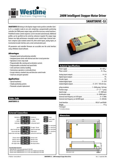
<strong>SMARTDRIVE</strong>-<strong>S3</strong> belongs to the bipolar stepper motor position controllers family.<br />
It is a complete ready-to-run unit, comprising a programmable positioning<br />
controller, the PWM power output stage, and all the necessary control interfaces.<br />
Predefined motion control sequences can be executed autonomously. Additional<br />
profiles can be specified via the serial bus whenever required. The output stage<br />
features two high performance sinusoidal current control loops. External interfaces<br />
comprises opto-isolated control I/Os, limit switch inputs, analog inputs, an<br />
incremental encoder interface and a serial communication port.<br />
All parameters and controller firmware are accessible over the serial interface<br />
using a Windows-based software.<br />
Advantages<br />
• Integrated speed and positioning controller<br />
• Integrated power driver with thermal and short-circuit protection<br />
• Operation in micro-step mode<br />
• Programmable idle, running and acceleration currents<br />
• Programmable acceleration and speed limits<br />
• Limit and home switches handling<br />
• Autonomous operation or externally driven<br />
• Accepts industry-standard step-and-direction control mode<br />
• Small size and quiet operation<br />
Applications<br />
• Special machinery<br />
• Simple positioning systems<br />
• Pneumatic actuator replacement<br />
Order Code<br />
<strong>SMARTDRIVE</strong>-<strong>S3</strong><br />
External Connections<br />
RXD (RS232) RX TX TXD (RS232)<br />
SHLD<br />
ground GND +5V 5V output / 100 mA<br />
+VS<br />
L+ (RS485) L+ L– L– (RS485)<br />
GND<br />
analog input AIN2 AIN1 analog input (speed)<br />
ground<br />
phase A encoder input<br />
index encoder input<br />
negative limit switch input<br />
GO input cathode<br />
DIR input cathode<br />
OFF input cathode<br />
RDY output emitter<br />
GND<br />
A<br />
Z<br />
LIMN<br />
+5V<br />
B<br />
BRK<br />
LIMP<br />
GOK GOA<br />
DIRK DIRA<br />
OFFK OFFA<br />
RDYE RDYC<br />
5V output / 100 mA<br />
phase B encoder input<br />
digital output<br />
positive limit switch input<br />
GO input anode<br />
DIR input anode<br />
OFF input anode<br />
RDY output collector<br />
Recommended connectors<br />
• Weidmüller B2L 3.5/8, 8 way socket block, RS 382-9602<br />
• Phoenix Contact COMBICON MSTB 2.5/3-ST-5.08, 3 way straight plug, RS 189-6026<br />
• Phoenix Contact COMBICON MSTB 2.5/5-ST-5.08, 5 way straight plug, RS 189-6048<br />
PHA+<br />
PHA–<br />
PHB+<br />
PHB–<br />
SHLD<br />
shield<br />
power supply<br />
ground<br />
A+ motor phase<br />
A– motor phase<br />
B+ motor phase<br />
B– motor phase<br />
shield<br />
<strong>200W</strong> <strong>Intelligent</strong> <strong>Stepper</strong> <strong>Motor</strong> <strong>Driver</strong><br />
Technical Specifications<br />
110<br />
100<br />
75<br />
<strong>SMARTDRIVE</strong> -<strong>S3</strong><br />
Power supply . . . . . . . . . . . . . . . . . . . . . . . . . . . . . . . . . . . . . . . . . . . . . . . 10÷48 VDC †<br />
Phase current . . . . . . . . . . . . . . . . . . . . . . . . . . . . . . . . . . . . . . . . . . . . . . . . . 0÷3 ARMS<br />
Analog inputs/outputs . . . . . . . . . . . . . . . . . . . . . . . . . . . . . . . . . . . . . . . . . . . . 0÷5 V<br />
Digital inputs/outputs . . . . . . . . . . . . . . . . . . . . . . . . . . . . . . . . . . . . . . . . . . . . . . . TTL<br />
Encoder inputs . . . . . . . . . . . . . . . . . . . . . . . . . . . . . . . . . . . . . . . . . . . . . . . . . . . . . TTL<br />
Isolated digital inputs . . . . . . . . . . . . . . . . . . . . . . . . . . . . . . . . . . . . . . . . . . . 0÷24 V<br />
Isolated digital outputs . . . . . . . . . . . . . . . . . . . . . . . . . . . . . 0÷24 V / 100 mA max.<br />
µStep resolution . . . . . . . . . . . . . . . . . . . . . . . . . . . . . . . . . 1÷2048 µstep / full step<br />
Position range . . . . . . . . . . . . . . . . . . . . . . . . . . . . . . . . . . . . . . . . . –2 31 ÷2 31 –1 µstep<br />
Speed range . . . . . . . . . . . . . . . . . . . . . . . . . . . . . . . . . . . . . . . . . . . . . . . 0÷3000 rpm<br />
Acceleration range . . . . . . . . . . . . . . . . . . . . . . . . . . . . . . . . . . . . . . . 0÷30000 rpm/s<br />
External clock frequency on A/B inputs . . . . . . . . . . . . . . . . . . . . . . . . . . 0÷12 MHz<br />
External clock frequency on GO/DIR inputs . . . . . . . . . . . . . . . . . . . . . . 0÷200 kHz<br />
Serial interface . . . . . . . . . . . . . . . . . . . . . . . . . . . . . . . . . . . . . . . . RS232 ‡ and RS485<br />
Weight . . . . . . . . . . . . . . . . . . . . . . . . . . . . . . . . . . . . . . . . . . . . . . . . . . . . . . . . . . 175 g<br />
† 5V on request<br />
‡ 2 m maximum distance<br />
Dimensions<br />
Dimensions in mm<br />
© Westline • www.westline.fr <strong>SMARTDRIVE</strong>-<strong>S3</strong> – <strong>200W</strong> <strong>Intelligent</strong> <strong>Stepper</strong> <strong>Motor</strong> <strong>Driver</strong> Rev. C / 3 september 2008<br />
4<br />
8<br />
5<br />
4,5<br />
50<br />
18<br />
8
<strong>SMARTDRIVE</strong> S Series – <strong>Intelligent</strong> <strong>Stepper</strong> <strong>Motor</strong> Controllers<br />
User’s Guide<br />
External connections<br />
Opto-isolated I/Os<br />
The A/K connections will drive the<br />
opto-isolator diode through the<br />
polarization circuit. The operating<br />
voltage on A input (related to K) is +5V to +24V without the need of an external<br />
limiting resistor. The C/E are the collector/emitter NPN transistor outputs of<br />
the opto-isolator.<br />
OFF – when activated the power output of the controller is disabled, the trajectory<br />
generator and the GO/DIR inputs are off.Toggling the OFF input will clear the<br />
current alarms and the current selected operating mode is reloaded. OFF input<br />
can be left unconnected if unused.<br />
GO and DIR operation is related to the actual operating mode. The operation is<br />
front or level sensitive depending the current operating mode.<br />
RDY is activated when the controller is ready to operate. During the execution of<br />
an order RDY is deactivated and will be activated again when the displacement is<br />
finish.<br />
Digital I/Os<br />
The digital I/Os are TTL compatible with internal<br />
pull-ups on the inputs.<br />
When activated LIMN will stop the movement in the negative direction.The current<br />
trajectory is discarded and the motor stops. The positive direction is not<br />
affected. LIMN can also be used as an origin input.<br />
When activated LIMP will stop the movement in the positive direction. The current<br />
trajectory is discarded and the motor stops. The negative direction is not<br />
affected.<br />
<br />
Because of internal pull-ups, LIMP and LIMN will be activated when left<br />
unconnected. When not in use they have to be disabled in software or<br />
tied to GND externally.<br />
BRK is a logical output reserved for special applications (driving a brake circuit for<br />
example).The internal preloaded modes don’t make use of that output.<br />
A, B and Z are inputs to the position feedback decoder. Special application software<br />
is needed to make use of these inputs. Typically A and B are quadrature<br />
inputs and Z is the zero index from an incremental encoder. Alternate function for<br />
A and B is pulse and sense inputs when this operating mode is selected.<br />
Analog I/Os<br />
AIN1 and AIN2 are two analog inputs provided for special applications. AIN1 is<br />
used as an external speed limit by the majority of the pre-programmed modes.<br />
When connected to an potentiometer the maximum speed can be adjusted.<br />
When the AIN1 is left unconnected an internal pull-up will apply maximum speed<br />
as specified by software.<br />
RS232 communication lines<br />
RX is an reception input and must be connected to TxD of the RS232 serial port.<br />
TX is an transmit output and must be connected to RxD of the RS232 serial port.<br />
An opto-isolated USB to RS232 adapter is available (P/N: ISOBUS-232).<br />
RS485 communication lines<br />
L+ and L– lines are used as a transmit/receive differential pair and must be<br />
connected to L+/L– of the an RS485 bus adapter. An opto-isolated USB to RS485<br />
adapter is available (P/N: ISOBUS-485).<br />
<strong>Motor</strong> outputs<br />
Page 2 © Westline • www.westline.fr<br />
The two coils A and B of the stepper motor will be<br />
connected to the PHA+/PHA– and PHB+/PHB–<br />
respectively. If you need to change the rotation sense<br />
you just have to reverse the connections for one of the<br />
coils.The connector provide also one pin for the shield<br />
grounding of the motor cable.<br />
Power Supply<br />
The controller needs a DC unregulated power supply. A dedicated connector is<br />
provided for +VS, GND and the cable shield connection SHLD. On signals side<br />
one +5Vdc output pin is provided to help the speed potentiometer connection<br />
or other conditioning circuitry. Another +5Vdc output pin is provided for the<br />
digital section. When an encoder or limit switche need power you can use that<br />
supply.<br />
<br />
The only opto-isolated signal pins are GO/DIR/OFF and RDY and they are<br />
provided for a PLC connection.<br />
Configuration<br />
The controller can be configured on the fly using an easy to use Windows 2000/XP<br />
software. First you have to connect the controller to the PC via the RS232 serial<br />
port or using an USB adapter. The available parameters are :<br />
• current operation mode<br />
• motor configuration : microstep resolution, current, PID constants<br />
• trajectory parameters<br />
• I/O polarities and limit switches configuration<br />
• alarms trigger levels
Operating modes (applications)<br />
The preloaded modes are controlled by the GO/DIR inputs.The RDY output can be<br />
used to monitor the status of the controller.<br />
An internal pulse generator can replace the GO input.The on time and the period<br />
is user adjustable. This generator is useful for implementing plenty of simple<br />
applications without the need of an external PLC.The pulse generator can be used<br />
only with the modes making use of the trajectory generator (not in pulse input<br />
mode)<br />
The trajectory generator will adjust the amplitude of the motor currents. When<br />
motor is stopped the hold current will maintain the rotor on the actual microstep<br />
position. During the acceleration and decceleration phases the acceleration current<br />
will be used and during the constant speed operation the work current will<br />
be used.<br />
Available modes are:<br />
• speed with level operated GO and DIR inputs<br />
• speed with level operated GOCW and GOCCW inputs<br />
• speed with front operated GO and DIR inputs (start/stop)<br />
• speed with front operated GOCW and GOCCW inputs (start/stop)<br />
• travel with GO and DIR inputs – act like an transport conveyor<br />
• travel with GOCW and GOCCW inputs – act like an transport conveyor<br />
• simple push-pull with GO/DIR inputs – act as an pneumatic jack<br />
• push-pull with GO/DIR inputs and position zeroing on limit switch<br />
• external quadrature clock with GO/DIR inputs<br />
• external clock and direction with GO/DIR inputs<br />
• serial bus operation for multi-axis synchronization<br />
Custom operation modes can be created on request.<br />
Speed GO/DIR<br />
DIR input will select the spinning direction and GO will<br />
start the motor.When GO is activated the motor will spin<br />
at the specified speed or accelerate/decelerate to reach<br />
the specified speed.The motor speed will ramp linearly to<br />
the target speed.<br />
Speed GOP/GON<br />
GOP input (GO) will spin the motor in positive direction<br />
and GON (DIR) will spin the motor in negative direction.<br />
The motor will operate at the specified speed or accelerate/decelerate<br />
to reach the specified speed. The motor<br />
<strong>SMARTDRIVE</strong> S Series – <strong>Intelligent</strong> <strong>Stepper</strong> <strong>Motor</strong> Controllers<br />
speed will ramp linearly to the target speed.The GOP input has priority over GON<br />
input.<br />
Speed STSP/DIR<br />
When the motor is stopped the selected front on STSP<br />
input (GO) will start the operation taking DIR input into<br />
account. When the motor is spinning the selected front<br />
on the same input will stop-it. Changing the polarity of<br />
the input will change the active front.<br />
Speed STSPP/STSPN<br />
When the motor is stopped the selected front on STSPP<br />
input (GO) will start the motor in positive direction and<br />
STSPN input (DIR) will start the motor in negative direction<br />
If it is operating the selected front on any of the two<br />
inputs will stop the motor.The STSPP input has the priority<br />
over STSPN input. Changing the polarity of the GO input will change the active<br />
front.<br />
Travel GO/DIR<br />
In this mode the motor is executing constant length<br />
movements. The DIR input will select the direction and<br />
the active front of the GO input will start the cycle. The<br />
movement length in micro steps is preloaded in the<br />
controller from the control panel on the PC and the profile<br />
is trapezoidal.If the limit switches are activated and one of them is reached the<br />
movement is stopped. Changing the polarity of the GO<br />
input will change the active front.<br />
Travel GOP/GON<br />
In this mode the motor is executing constant length<br />
movements. The GOP and GON inputs will start the cycle<br />
© Westline • www.westline.fr Page 3
<strong>SMARTDRIVE</strong> S Series – <strong>Intelligent</strong> <strong>Stepper</strong> <strong>Motor</strong> Controllers<br />
in positive or negative direction. The movement length in micro steps is preloaded<br />
in the controller from the control panel on the PC and the profile is trapezoidal.<br />
If the limit switches are activated and one of them is reached the movement<br />
is stopped. Changing the polarity of the input will change the active front. GOP<br />
input has the priority over the GON input.<br />
<br />
When the auto-GO timer is used only positive movements are possible.<br />
Simple jack (push-pull)<br />
In this mode the motor will execute one push-pull movement<br />
over a preloaded distance like a pneumatic jack.The<br />
movement is decomposed in two phases: push and pull.<br />
The DIR input will select the direction of the movement<br />
and the selected front on the GO input will initiate the<br />
push phase. Once the push is executed the pull phase will be initiated only when<br />
the GO input is deactivated.<br />
If one full cycle is executed the motor return to the initial position.<br />
The movement length in micro steps is preloaded in the controller from the<br />
control panel on the PC and the profile is trapezoidal.If the limit switches are activated<br />
and one of them is reached the movement is stopped. Changing the polarity<br />
of the GO input will change the active front.<br />
Push-pull with zeroing on LIMN switch<br />
In this mode the motor will execute one positive movement<br />
over a user preloaded distance. By toggling the ALT<br />
input (DIR) the user has the choice of two preloaded distances.<br />
When GO is activated the push phase is initiated.<br />
The motor will initiate the pull phase only if the GO input<br />
is deactivated. In the pull phase the motor will spin in negative direction until the<br />
LIMN switch is reached and then it will reverse the direction at a lower speed to<br />
find the edge of the LIMN switch.The user has the possibility to preload a position<br />
offset relative to the edge of the limit switch.The push distance is preloaded from<br />
the PC but can be reduced by the use of LIMP switch. Changing the polarity of the<br />
Page 4 © Westline • www.westline.fr<br />
GO input will change the active front.<br />
External clock with DIR<br />
In this mode the motor advance one micro-step for every<br />
active front on the CLK input (GO). Changing the polarity<br />
of the GO input will change the active front.The DIR input<br />
will select the spinning direction.<br />
<br />
1. Auto-GO, zeroing and limit switches are not operating in this mode.<br />
2. You need to select a significant stop current in order to be able to<br />
maintain the the rotor micro-step position between two clocks.<br />
External clock A quad B<br />
In this mode the CLKA and CLKB inputs are two quadrature<br />
encoded clock inputs (90° out of phase).The inputs<br />
are decoded like for an incremental encoder in order to<br />
extract the clock and direction signals. The input resolution is multiplied by 4 in<br />
the decoding circuit so one micro-step is generated at each front of the A and B<br />
inputs. The spinning direction will depend on the phase relation between the<br />
inputs and can be changed by reversing the polarity of one of the A or B signals.<br />
<br />
1. Auto-GO, zeroing and limit switches are not operating in this mode.<br />
2. You need to select a significant stop current in order to be able to<br />
maintain the the rotor micro-step position between two clocks.<br />
Special options<br />
Different special functions can be applied to all or to some of the application<br />
modes.This functions can be activated or deactivated using the configuration<br />
software.<br />
Position zeroing<br />
This function can be executed each time when the current operating mode is activated,<br />
for example after power-up or after disabling the OFF input. This function<br />
is the same as described for the mode “Push-pull with zeroing on LIMN switch”.<br />
The motor will go to the LIMN switch and will reset the position register.<br />
Offsetting the zero is also possible. The operation of this function ignores the<br />
selection status of the LIMN switch in software. Be sure the LIMN signal is long<br />
enough to allow the motor to stop inside the LIMN switch.<br />
Auto-GO<br />
All the operating modes except external clock can be started by the internal auto-<br />
GO timer.The on time and period of the timer can be programmed with 1 millisecond<br />
resolution. A 0 value in the period parameter will deactivate the auto-GO<br />
timer.<br />
Limit switches<br />
The limit switches can stop the movement in the corresponding direction when<br />
activated.When the switch is reached the motor will stop using a specified deceleration<br />
different of that used in the normal trajectories. If you enter 0 in that<br />
parameter the motor will stop abruptly with maximum deceleration.


