2-wire transmitter with hart® protocol - PR Electronics Inc.
2-wire transmitter with hart® protocol - PR Electronics Inc.
2-wire transmitter with hart® protocol - PR Electronics Inc.

Create successful ePaper yourself
Turn your PDF publications into a flip-book with our unique Google optimized e-Paper software.
5337A<br />
Application:<br />
• Linearised temperature measurement <strong>with</strong> TC and RTD<br />
sensors e.g. Pt100 and Ni100.<br />
• HART ® communication and 4...20 mA analogue PV<br />
output for individual, difference or average temperature<br />
measurement of up to two RTD or TC input sensors.<br />
• Conversion of linear resistance to a standard analogue<br />
current signal, e.g from valves or Ohmic level sensors.<br />
• Amplification of bipolar mV signals to standard<br />
4...20 mA current signals.<br />
• Up to 63 <strong>transmitter</strong>s (HART ® 7) can be connected in a<br />
multidrop communication setup.<br />
Technical characteristics:<br />
• HART ® <strong>protocol</strong> revision can be changed by user<br />
configuration to either HART ® 5 or HART ® 7 <strong>protocol</strong>.<br />
• The HART ® 7 <strong>protocol</strong> offers:<br />
∙ Long Tag numbers of up to 32 characters.<br />
∙ Enhanced Burst Mode and Event notification <strong>with</strong><br />
time stamping.<br />
∙ Device variable and status mapping to any dynamic<br />
variable PV, SV, TV or QV.<br />
∙ Process signal trend measurement <strong>with</strong> logs and<br />
summary data.<br />
∙ Automatic event notification <strong>with</strong> time stamps.<br />
∙ Command aggregation for higher communication<br />
efficiency.<br />
• 5337A is designed according to strict safety requirements<br />
and is therefore suitable for applications in SIL<br />
installations.<br />
• Continuous check of vital stored data.<br />
• Meeting the NAMUR NE21 recommendations, the<br />
5337 HART ® <strong>transmitter</strong> ensures top measurement<br />
performance in harsh EMC environments.<br />
Additionally, the 5337 meets NAMUR NE43 and NE89<br />
recommendations.<br />
Mounting / installation / programming:<br />
• For DIN form B sensor head or DIN rail mounting via<br />
the <strong>PR</strong> fitting type 8421.<br />
• Configuration via standard HART ® communication<br />
interfaces or by <strong>PR</strong> 5909 Loop Link.<br />
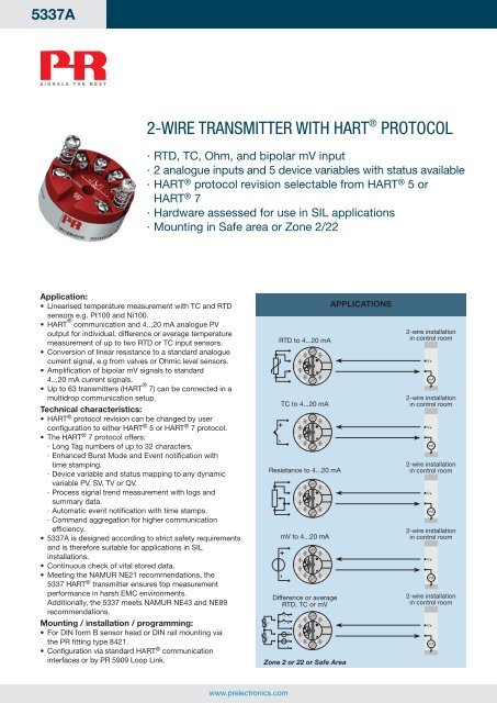
2-WIRE TRANSMITTER WITH HART ® <strong>PR</strong>OTOCOL<br />
∙ RTD, TC, Ohm, and bipolar mV input<br />
∙ 2 analogue inputs and 5 device variables <strong>with</strong> status available<br />
∙ HART ® <strong>protocol</strong> revision selectable from HART ® 5 or<br />
HART ® 7<br />
∙ Hardware assessed for use in SIL applications<br />
∙ Mounting in Safe area or Zone 2/22<br />
www.prelectronics.com<br />
2 1<br />
+<br />
-<br />
RTD to 4...20 mA<br />
+<br />
-<br />
-<br />
-<br />
-<br />
-<br />
+ -<br />
+ -<br />
+ -<br />
+ -<br />
+ -<br />
TC to 4...20 mA<br />
+ -<br />
+ -<br />
Resistance to 4...20 mA<br />
+ -<br />
mV to 4...20 mA<br />
+<br />
+<br />
+ -<br />
Difference or average<br />
RTD, TC or mV<br />
2<br />
1<br />
+<br />
+<br />
2 1<br />
+ -<br />
Zone 2 or 22 or Safe Area<br />
ApplicATions<br />
2-<strong>wire</strong> installation<br />
in control room<br />
V+<br />
mA<br />
2-<strong>wire</strong> installation<br />
in control room<br />
V+<br />
mA<br />
2-<strong>wire</strong> installation<br />
in control room<br />
V+<br />
mA<br />
2-<strong>wire</strong> installation<br />
in control room<br />
V+<br />
mA<br />
2-<strong>wire</strong> installation<br />
in control room<br />
V+<br />
mA
order codes for 5337A:<br />
Type<br />
5337A<br />
Connections:<br />
RTD, 2-<strong>wire</strong> RTD, 3-<strong>wire</strong> RTD, 4-<strong>wire</strong><br />
3 4 5 6 3 4 5 6 3 4 5 6<br />
Resistance, 2-<strong>wire</strong> Resistance, 3-<strong>wire</strong> Resistance, 4-<strong>wire</strong><br />
3 4 5 6 3 4 5 6 3 4 5 6<br />
Environmental conditions:<br />
Specifications range................................. -40°C to +85°C<br />
Calibration temperature............................ 20...28°C<br />
Relative humidity ...................................... < 95% RH (non-cond.)<br />
Protection degree (encl./terminal) ............ IP68/IP00<br />
Vibration ................................................... IEC 60068-2-6 Test FC<br />
Lloyd’s specification no. 1........................ 4 g / 2...100 Hz<br />
Mechanical specifications:<br />
Dimensions .............................................. Ø 44 x 20.2 mm<br />
Weight approx. ......................................... 50 g<br />
Max. <strong>wire</strong> size........................................... 1 x1.5 mm 2 stranded <strong>wire</strong><br />
Screw terminal torque .............................. 0.4 Nm<br />
common electrical specifications:<br />
Supply voltage, DC .................................. 8.0...35 V<br />
Voltage drop ............................................. 8.0 V<br />
Isolation - test / working........................... 1.5 kVAC / 50 VAC<br />
Signal / noise ratio.................................... > 60 dB<br />
Communications interface ....................... Loop Link & HART ®<br />
Response time (programmable).. ............. 1...60 s<br />
TC B 1 accuracy specification range ......... > 400°C<br />
TC B 2 accuracy specification range ......... > 160°C < 400°C<br />
TC B 3 accuracy specification range ......... > 85°C < 160°C<br />
TC B 4 accuracy specification range ......... < 85°C<br />
TC cold junction compensation ............... < ±1.0°C<br />
Max. offset on input signal ....................... 50% of selec. max. value<br />
Segurança<br />
INMETRO OCP 0034<br />
Input:<br />
Accuracy, the greater of general and basic values:<br />
General values<br />
Absolute<br />
Temperature<br />
Input type accuracy<br />
coefficient<br />
All ≤ ±0.05% of span ≤ ±0.005% of span / °C<br />
Basic values<br />
Basic<br />
Temperature<br />
Input type<br />
accuracy<br />
coefficient<br />
Pt50 - Pt1000 ≤ ±0.1°C ≤ ±0.005°C/°C<br />
Ni50 - Ni1000 ≤ ±0.2°C ≤ ±0.005°C/°C<br />
Lin. R ≤ ±0.1 Ω ≤ ±5 mΩ / °C<br />
Volt<br />
TC type:<br />
≤ ±10 µV ≤ ±0.5 µV / °C<br />
E, J, K, L, N, T, U<br />
TC type:<br />
≤ ±0.5°C ≤ ±0.025°C / °C<br />
B 1 , Lr, R, S, W3, W5 ≤ ±1°C ≤ ±0.1°C / °C<br />
TC type:B 2 ≤ ±3°C ≤ ±0.3°C / °C<br />
TC type:B3 ≤ ±8°C ≤ ±0.8°C / °C<br />
TC type:B 4 not specified not specified<br />
EMC immunity influence ................................ < ±0.1% of span<br />
Extended EMC immunity:<br />
NAMUR NE 21, A criterion, burst................... < ±1% of span<br />
TC, internal CJC TC, external CJC mV<br />
3 4 5 6 3 4 5 6 3 4 5 6<br />
-<br />
+<br />
RTD, difference<br />
or average<br />
3 4 5 6<br />
2<br />
1<br />
Accessories:<br />
5909 = loop link UsB interface and pReset software<br />
8421 = Din rail clip<br />
-<br />
+<br />
TC, difference<br />
or average<br />
3 4 5 6<br />
2<br />
- +<br />
1<br />
- +<br />
input specifications:<br />
RTD input types:<br />
RTD<br />
type<br />
Pt100<br />
Ni100<br />
Lin. R<br />
Min.<br />
value<br />
-200°C<br />
-60°C<br />
0 Ω<br />
Pt50, Pt100, Pt200, Pt500, Pt1000, Ni50, Ni100, Ni120, Ni1000<br />
Cable resistance per <strong>wire</strong> (max.) .............. 5 Ω<br />
(up to 50 Ω per <strong>wire</strong> is possible <strong>with</strong> reduced measurement accuracy)<br />
Sensor current.......................................... Nom. 0.2 mA<br />
mV and Tc input types:<br />
Type<br />
B<br />
E<br />
J<br />
K<br />
L<br />
Lr<br />
N<br />
R<br />
S<br />
T<br />
U<br />
W3<br />
W5<br />
Min.<br />
temperature<br />
0°C<br />
-100°C<br />
-100°C<br />
-180°C<br />
-200°C<br />
-200°C<br />
-180°C<br />
-50°C<br />
-50°C<br />
-200°C<br />
-200°C<br />
0°C<br />
0°C<br />
-<br />
Cold junction compensation:<br />
Constant, internal or external via a Pt100 or Ni100 sensor<br />
+<br />
mV, difference<br />
or average<br />
3 4 5 6<br />
2<br />
-<br />
+<br />
1<br />
-<br />
+<br />
Max.<br />
values<br />
+850°C<br />
+250°C<br />
7000 Ω<br />
Max.<br />
temperature<br />
+1820°C<br />
+1000°C<br />
+1200°C<br />
+1372°C<br />
+900°C<br />
+800°C<br />
+1300°C<br />
+1760°C<br />
+1760°C<br />
+400°C<br />
+600°C<br />
+2300°C<br />
+2300°C<br />
Min.<br />
span<br />
10°C<br />
10°C<br />
25 Ω<br />
Output:<br />
2-<strong>wire</strong> installation<br />
1 2<br />
mA -<br />
Voltage input range .................................. -800...+800 mV<br />
Min. span.................................................. 2.5 mV<br />
Input resistance........................................ 10 MΩ<br />
current output and HART ® :<br />
Signal range ............................................. 4...20 mA<br />
Min. signal range ...................................... 16 mA<br />
Updating time........................................... 440 ms<br />
Load resistance ........................................ ≤ (Vsupply - 8) / 0.023 [Ω]<br />
Sensor error detection, programmable .... 3.5...23 mA<br />
NAMUR NE43 Upscale............................. 23 mA<br />
NAMUR NE43 Downscale........................ 3.5 mA<br />
HART ® <strong>protocol</strong> revisions ......................... HART ® 5 and HART ® 7<br />
Approvals:<br />
EMC 2004/108/EC ................................... EN 61326-1<br />
GOST R<br />
Marine:<br />
Det Norske Veritas, Ships & Offshore....... Stand. f. Certific. No. 2.4<br />
Ex:<br />
ATEX 94/9/EC........................................... KEMA 03ATEX1508 X<br />
IECEx........................................................ KEM 10.0083 X<br />
INMETRO certificate................................. NCC 12.0844 X<br />
Functional safety:<br />
Hardware assessed for use in SIL applications<br />
FMEDA report - www.prelectronics.com<br />
+<br />
Standard<br />
IEC 60751<br />
DIN 43760<br />
-----<br />
Min.<br />
span Standard<br />
100°C<br />
50°C<br />
50°C<br />
50°C<br />
50°C<br />
50°C<br />
50°C<br />
100°C<br />
100°C<br />
50°C<br />
50°C<br />
100°C<br />
100°C<br />
IEC584<br />
IEC584<br />
IEC584<br />
IEC584<br />
DIN 43710<br />
GOST 3044-84<br />
IEC584<br />
IEC584<br />
IEC584<br />
IEC584<br />
DIN 43710<br />
ASTM E988-90<br />
ASTM E988-90<br />
5337AY102-UK (1306)