MGC-25/50/100 MGC+50/100 - Polycom
MGC-25/50/100 MGC+50/100 - Polycom
MGC-25/50/100 MGC+50/100 - Polycom

Create successful ePaper yourself
Turn your PDF publications into a flip-book with our unique Google optimized e-Paper software.
<strong>MGC</strong>-<strong>25</strong>/<strong>50</strong>/<strong>100</strong><br />
<strong>MGC</strong>+<strong>50</strong>/<strong>100</strong><br />
Release Notes<br />
Version 7.5<br />
February 2006<br />
DOC2134A
Copyright © 2006 <strong>Polycom</strong>, Inc.<br />
All Rights Reserved<br />
All text and figures included in this publication are the exclusive property of <strong>Polycom</strong>, Inc., and may not be copied, reproduced or used in<br />
any way without the express written permission of <strong>Polycom</strong>, Inc. Information in this document is subject to change without notice.<br />
This document also contains registered trademarks and service marks that are owned by their respective companies or organizations.<br />
If you have any comments or suggestions regarding this document, please send them via e-mail to info@polycom.com.<br />
Catalog No. DOC2134A<br />
Version 7.5<br />
Notice<br />
While reasonable effort was made to ensure that the information in this document was complete and accurate at the time of printing,<br />
<strong>Polycom</strong>, Inc. cannot assure the accuracy of such information. Changes and/or corrections to the information contained in this document<br />
may be incorporated into future issues.
Table of Contents<br />
Version 7.5 - New Features List............................................................1<br />
Version 7.5 Upgrade Package Contents..............................................5<br />
Prior to Installation and SW Upgrade ..................................................6<br />
Hardware Update Notice ................................................................................................6<br />
Control Unit Update Notice ...................................................................................7<br />
Version 7.5 Interoperability Table .................................................................................8<br />
Software Upgrade Procedure .............................................................10<br />
Upgrade Checklist ........................................................................................................10<br />
MCU Disk Space Verification .....................................................................................10<br />
Dongle Upgrade ...........................................................................................................11<br />
Dongle Information ..............................................................................................11<br />
Dongle Upgrade Instructions .........................................................................12<br />
<strong>MGC</strong>-<strong>50</strong>/<strong>MGC</strong>-<strong>100</strong> .......................................................................................12<br />
<strong>MGC</strong>-<strong>25</strong> .........................................................................................................13<br />
Downloading the Dongle File ..............................................................................14<br />
Installing the Dongle File .....................................................................................15<br />
<strong>MGC</strong> Unit Software Upgrade Procedure .....................................................................16<br />
Upgrading from a Version using Password for Entry Queue Routing .................16<br />
Upgrading from a Version using Numeric ID for Entry Queue Routing .............17<br />
Removal of Redundant Configuration Files ................................................................17<br />
Downloading the Software to the MCU ......................................................................17<br />
Installing the <strong>MGC</strong> Manager Software ........................................................................19<br />
Manual Installation of the Default Message Services ..................................................19<br />
Updating the Entry Queue Services .............................................................................20<br />
Detailed Description - Video ...............................................................21<br />
Video Support for Start Conference requires Chairperson ..........................................21<br />
Detailed Description .............................................................................................21<br />
Detailed Description - General ...........................................................23<br />
Network Time Protocol (NTP) for XPEK Systems .....................................................23<br />
Detailed Description .............................................................................................23<br />
Secure Socket Layer (SSL) ..........................................................................................<strong>25</strong><br />
Detailed Description .............................................................................................<strong>25</strong><br />
H.239/People+Content Star Cascading ........................................................................30<br />
Detailed Description .............................................................................................30<br />
Ad Hoc Auto Cascade ..................................................................................................31<br />
Detailed Description .............................................................................................31<br />
Monitoring Auto Cascaded Conference Links ..............................................33<br />
Limitations ............................................................................................................33<br />
Faulty Participant in Red .............................................................................................34<br />
Detailed Description .............................................................................................34<br />
i
<strong>MGC</strong> Release Notes - Version 7.5<br />
ii<br />
HTTP File Transfer Mode ........................................................................................... 35<br />
Detailed Description ............................................................................................ 35<br />
Same Layout Option in Video Switching Conferences ............................................... 36<br />
Direct IP Dial-in .......................................................................................................... 37<br />
Detailed Description ............................................................................................ 37<br />
Direct End Point Dialing ...................................................................................... 37<br />
IP to ISDN Gateway Call (without Gatekeeper) .................................................. 37<br />
SIP Factory .................................................................................................................. 38<br />
Detailed Description ............................................................................................ 38<br />
Nortel Environment Flag Settings ............................................................................... 40<br />
<strong>MGC</strong>+ Predefined IP only Entry Queues and Meeting Rooms .................................. 41<br />
Corrections, Pending Issues and Limitations...................................43<br />
Corrections between Versions V.7.0.2 and V.7.5 ....................................................... 43<br />
Corrections between Versions V.7.0.1 and V.7.0.2 .................................................... 44<br />
Corrections between Versions V.7.0 and V.7.0.1 ....................................................... 47<br />
Version 7.5 Pending Issues .......................................................................................... 49<br />
Version 7.5 System Limitations .................................................................................. 54<br />
Appendix A - Falcon Diagnostic Tool................................................65<br />
Detailed Description ............................................................................................ 65<br />
Test Description ........................................................................................................... 66<br />
Starting the Falcon Diagnostic Tool ............................................................................ 70<br />
Falcon Main Window .......................................................................................... 70<br />
Setting the Log Files Path .................................................................................... 73<br />
Connecting to an MCU ........................................................................................ 74<br />
Running Diagnostic Tests ............................................................................................ 75<br />
Test Results ................................................................................................................. 79<br />
Disconnecting from the Falcon Diagnostic Tool ......................................................... 80<br />
Appendix - Adding an MCU to the Network .............................................................. 81<br />
Test Glossary ............................................................................................................... 82<br />
Log File Report Examples ........................................................................................... 83
Version 7.5 - New Features List<br />
The following table lists the new features in Version 7.5.<br />
Table 1: New Features List<br />
Category Feature Name Description<br />
1. Video H.264 SD/HD in Video<br />
Switching conferences<br />
2. Video Increased Frame Rate in<br />
H.264 CP conferences<br />
3. Video H.264 up to 2 Mbps in<br />
VideoSwitching<br />
Conferences<br />
Version 7.5 - New Features List<br />
H.264 Standard Definition (SD), High<br />
Definition (HD) and VSX 8000 (version<br />
8.0) HRR resolutions are supported in<br />
Video Switching conferences.<br />
Set the system.cfg flag:<br />
ENABLE_HD_SD_IN_FIXED_MODE=<br />
YES (default =NO). When YES, the<br />
Highest Common mode is enabled.<br />
Higher Frame rates in H.264 CP<br />
conferences. The MCU now supports<br />
frame rates up to 30 FPS in CP<br />
conferences.<br />
In H.264 VideoSwitching Conferences,<br />
the maximum Line Rate capability is<br />
1920 Kbps.<br />
Supported in <strong>MGC</strong> version 7.03.<br />
4. Video H.264 Fixed Mode H.264 Fixed mode can be used with<br />
cascaded conferences by setting the<br />
H.264_VSW_AUTO flag to YES. These<br />
flag settings forces all endpoints to use<br />
predefined conference resolution and<br />
frame rates.<br />
5. Video Video Support for Start<br />
Conference requires<br />
Chairperson<br />
6. IP H.323 dial-out automatic<br />
redial<br />
This feature is now available for video<br />
conferences.<br />
When the conference is set to Wait for<br />
Chairperson and participants connect to<br />
the conference before the chairperson,<br />
the conference is placed on hold.<br />
When an H.323 dial-out call fails to<br />
connect because the endpoint could not<br />
be reached (for example, the endpoint is<br />
busy), the system can be set to<br />
automatically redial the endpoint.<br />
Set the system.cfg flag:<br />
ENABLE_H323_REDIAL=YES.<br />
7. IP Direct IP Dial-in The MCU supports two new IP Dial-in<br />
methods:<br />
• Direct Endpoint Dialing (Without<br />
Gatekeeper)<br />
• IP to ISDN Gateway Call (without<br />
Gatekeeper)<br />
1
<strong>MGC</strong> Release Notes - Version 7.5<br />
2<br />
Table 1: New Features List (Continued)<br />
Category Feature Name Description<br />
8. IP SIP REINVITE SIP protocol allows ways of changing<br />
one or more parameters in an existing<br />
session. It is performed by sending a<br />
REINVITE request with the desirable<br />
mode to the other SIP entities in the<br />
conference.<br />
Version 7.5 supports the SIP REINVITE<br />
request sent by the remote SIP endpoint<br />
to the <strong>MGC</strong> in the following instances:<br />
• Party Media - change in the<br />
participant’s IP address.<br />
• Conference Media - change in the<br />
participant status that is informed to<br />
the conference, such as mute and<br />
hold.<br />
• Change Mode - changes that affect<br />
the conference media and may affect<br />
other participants as a result, such as<br />
change in the video protocol.<br />
• Later Video - Upgrade the SIP<br />
connection from audio only to video.<br />
9. IP SIP OPTIONS Support for SIP RFC-3261 (OPTIONS)<br />
that allows a UA (User Agent) to query<br />
another UA or a proxy server for its SIP<br />
and media capabilities.<br />
10. IP SIP REFER Support for SIP RFC-3265 (REFER) that<br />
instructs the recipient of the REFER<br />
request to contact a third party using the<br />
contact information included with the<br />
REFER request. This allows any SIP UA<br />
to send the URI of another UA to the<br />
conference and instructs the conference<br />
to create a new dial-out participant and<br />
dial to it.<br />
11. IP SIP Factory Allows SIP endpoints to create ad hoc<br />
conference and automatically connect to<br />
the conference.<br />
12. IP Microsoft LCS support This version supports multipoint SIP<br />
conferencing in a Microsoft environment:<br />
• Microsoft LCS 2005, SP1,<br />
• Office Communicator version 1.0,<br />
• Windows Messenger version 5.1,<br />
• Installed desktop and group video<br />
conferencing systems PVX versions<br />
8.0 & 8.0.1; VSX 8.0 & 8.0.3.<br />
• <strong>MGC</strong> Manager 7.5<br />
Note: This product requires purchase of<br />
a license.
Table 1: New Features List (Continued)<br />
Category Feature Name Description<br />
13. Microsoft LCS support<br />
(con’t)<br />
14. IP IP Bridge Higher<br />
Capacity<br />
Version 7.5 - New Features List<br />
With <strong>MGC</strong> 7.5 (MS integrator phase 3)<br />
<strong>Polycom</strong> now supports the full set of OC<br />
Conferencing capabilities based on the<br />
MS SIP-CX protocol.<br />
For a detailed description of the Microsoft<br />
solution see the Microsoft Deployment<br />
Guide.<br />
The maximum bridge capacity in IP<br />
Video Switching conferences is<br />
increased.<br />
15. IP Nortel The system automatically detects the<br />
Nortel environment and changes the<br />
working mode accordingly (no need to<br />
set the Nortel flag in the system.cfg).<br />
However, if you do not see video with the<br />
Nortel endpoints, you may need to<br />
modify three flags in the system.cfg file.<br />
Note: This product requires purchase of<br />
a license.<br />
16. IP H.323 FECC T.140 Closed Captioning is supported<br />
with H.323 FECC.<br />
17. General Network Time Protocol<br />
(NTP) for XPEK<br />
Systems<br />
18. General Secure Socket Layer<br />
(SSL)<br />
19. General H.239/People+Content<br />
Star Cascading<br />
The Network Time Protocol (NTP) allows<br />
the MCU to synchronize the internal<br />
MCU control unit’s clock with an external<br />
NTP server to assure accurate time and<br />
synchronized controls.<br />
SSL (Secure Socket Layer) enables<br />
secure HTTP connection on MCU’s with<br />
XPEK Operating Systems. Available on<br />
the <strong>MGC</strong> Manager, WebCommander and<br />
API calls.<br />
H.239/People+Content Star Cascading is<br />
available with H.320 (ISDN and MPI) &<br />
H.323 Video Switching conferences.<br />
20. General Ad Hoc Auto Cascade Ad Hoc conferences can be<br />
automatically cascaded. When an<br />
identical Numeric ID is used for each<br />
conference, the WebCommander<br />
automatically cascades the conferences.<br />
21. General Faulty Participant<br />
Marked in Red<br />
22. General HTTP File Transfer<br />
Mode<br />
23. General Same Layout Option in<br />
Video Switching<br />
Conferences<br />
A “Faulty” participant connected to a<br />
conference has their background color<br />
marked red for improved visibility.<br />
Transfer of files using HTTP mode can<br />
be used in addition to FTP mode of<br />
operation.<br />
Video Switching conferences support the<br />
Same Layout mode.<br />
3
<strong>MGC</strong> Release Notes - Version 7.5<br />
4<br />
Table 1: New Features List (Continued)<br />
Category Feature Name Description<br />
24. General Circular Resource<br />
Mapping<br />
<strong>25</strong>. General <strong>MGC</strong>+ Predefined IP<br />
Only Entry Queues and<br />
Meeting Rooms<br />
26. General New Diagnostic tool<br />
(Falcon)<br />
When the MCU is set to circular mode,<br />
Audio+ and Video+ card resources are<br />
allocated onto the next sequential unit<br />
that is free on a plus (+) card.<br />
Set the system.cfg flag:<br />
CIRCULAR_MAPPING_MODE_FOR_<br />
AUDIO_VIDEO_PLUS=YES (default<br />
=YES).<br />
The <strong>MGC</strong>+ unit is shipped with two Entry<br />
Queues and eight Meeting Rooms and<br />
the appropriate EQ and IVR Services.<br />
The Falcon diagnostic tool is an add-on<br />
to the <strong>MGC</strong> Manager application that<br />
enables you to run diagnostic tests on<br />
the hardware of <strong>MGC</strong>. The Diagnostic<br />
Tool option is accessed from the Options<br />
menu in the <strong>MGC</strong> Manager application.
Version 7.5 Upgrade Package Contents<br />
Version 7.5 upgrade package includes the following items:<br />
• <strong>MGC</strong> Software CD<br />
— <strong>MGC</strong> Manager software<br />
— <strong>MGC</strong> unit software<br />
— External DB Tools<br />
Version 7.5 Upgrade Package Contents<br />
• Documentation describing how to work with an external database application<br />
for Ad Hoc Conferencing and Conference Access Authentication<br />
• Sample Scripts for working with an external database application<br />
— IVR<br />
• Default Message Services in English<br />
• Message Services in Spanish<br />
• Voice Messages in both *.wav and *.aca format<br />
— File: system.cfg<br />
• <strong>MGC</strong> Documentation<br />
— Version 7.5 Release Notes<br />
— <strong>MGC</strong> Manager User’s Guide, Volume I<br />
— <strong>MGC</strong> Manager User’s Guide, Volume II<br />
— <strong>MGC</strong> Manager User’s Guide, VoicePlus Edition<br />
— <strong>MGC</strong> Administrator’s Guide<br />
— <strong>MGC</strong>-<strong>50</strong>/<strong>MGC</strong>-<strong>100</strong> Getting Started Guide<br />
— <strong>MGC</strong>+<strong>50</strong>/<strong>MGC</strong>+<strong>100</strong> Getting Started Guide<br />
— <strong>MGC</strong>-<strong>25</strong> Getting Started Guide<br />
— <strong>MGC</strong>-<strong>50</strong>/<strong>MGC</strong>-<strong>100</strong> Hardware and Installation Guide<br />
— <strong>MGC</strong>+<strong>50</strong>/<strong>MGC</strong>+<strong>100</strong> Hardware and Installation Guide<br />
— Microsoft—<strong>Polycom</strong> Deployment Guide, Phase I<br />
— Nortel—<strong>Polycom</strong> Deployment Guide, Phase I<br />
5
<strong>MGC</strong> Release Notes - Version 7.5<br />
Prior to Installation and SW Upgrade<br />
6<br />
Reservations are automatically restored after software upgrade and you therefore do not<br />
need to Restore reservations. It is recommended that you backup reservations using the<br />
Reservations Backup utility. Reservation backups are not compatible between versions,<br />
therefore you should backup reservations before and after upgrade.<br />
Hardware Update Notice<br />
Please make sure the hardware listed below is used with the listed <strong>MGC</strong> version and <strong>MGC</strong><br />
Manager versions:<br />
# Board Type<br />
H/W<br />
Version<br />
<strong>MGC</strong> Versions SIP H.264 H.239 AES<br />
<strong>MGC</strong>-<strong>50</strong>/<strong>MGC</strong>+<strong>50</strong>/<strong>MGC</strong>-<strong>100</strong>/<strong>MGC</strong>+<strong>100</strong><br />
1. Audio 12/24* 1 V1.04-7 V5.0 and later n/a n/a n/a n/a<br />
2. Audio+12/24 V1.04-7<br />
& V1.23<br />
V5.17,<br />
V6.03 and later<br />
n/a n/a n/a n/a<br />
3. Audio 24/48* 1 V1.04-7 V5.0 and later n/a n/a n/a n/a<br />
4. Audio+24/48 V1.04-7,<br />
& V1.23<br />
V5.17,<br />
V6.03 and later<br />
n/a n/a n/a n/a<br />
5. Audio 48/96* 1 V1.04-7 V5.0 and later n/a n/a n/a n/a<br />
6. Audio+48/96 V1.04-7,<br />
& V1.23<br />
7. Video+8 V1.23–<br />
V1.31<br />
V5.17,<br />
V6.03 and later<br />
8. Video+8 V2.03 V5.17,<br />
V6.03 and later<br />
n/a n/a n/a n/a<br />
V5.0 and later n/a n/a n/a n/a<br />
n/a n/a n/a n/a<br />
9. IP12 V1.45 V5.0 and later NO YES YES NO<br />
10. IP24 V2.01-4<br />
&<br />
V2.21-5<br />
V5.0 and later NO YES YES NO<br />
11. IP48 V4.22-5 V5.0 and later YES YES YES YES<br />
12. IP+12 V4.43 V6.03 and later YES YES YES YES<br />
13. IP+24 V4.43 V6.03 and later YES YES YES YES<br />
14. IP+48 V4.44 V6.03 and later YES YES YES YES<br />
15. IP48 I/O* 2 V1.01 &<br />
V1.21<br />
V5.0 and later YES YES YES YES<br />
16. IP+48 I/O* 3 V1.21 V6.0 and later YES YES YES YES<br />
17. MUX+10 V4.42 V7.0 and later n/a n/a n/a YES
# Board Type<br />
Prior to Installation and SW Upgrade<br />
*1—These cards are not supported with the <strong>MGC</strong>+<strong>50</strong>/<strong>100</strong>. Only Audio+12/24, Audio+24/48 and<br />
Audio+48/96 are supported with the <strong>MGC</strong>+<strong>50</strong>/<strong>100</strong>.<br />
*2—Does not work with the new IP+ card V4.43 (IP+12/24/48)<br />
*3—Backward compatible; shipped with IP+ V4.43 (<strong>MGC</strong> 7.0.0)<br />
Please be aware that upgrading the <strong>MGC</strong>-<strong>100</strong> hardware may require upgrading the power<br />
supplies (the <strong>MGC</strong>-<strong>50</strong> has one 600W power supply). As a general guideline:<br />
• Each board consumes up to 40W apart from video boards.<br />
• The Video+8 board consumes 75W, the Video6 board (older video board) consumes<br />
55W and the Dual Video (2 Video6 boards tied together) consumes 110W.<br />
• The Control Unit consumes 30W.<br />
• Each older power supply unit (marked as PWR on its front panel) provides 300W (AC<br />
& DC).<br />
• Each new power supply unit (marked as POWER on its front panel) provides 4<strong>50</strong>W<br />
(AC & DC).<br />
Control Unit Update Notice<br />
18. MUX+20 V4.43 V7.0 and later n/a n/a n/a YES<br />
19. MUX+40 V4.44 V7.0 and later n/a n/a n/a YES<br />
<strong>MGC</strong>-<strong>25</strong><br />
H/W<br />
Version<br />
20. IPN V1.24 &<br />
V1.26<br />
21. IPN V1.41 V6.11, V7.0 and<br />
later<br />
V5.0 and later YES YES YES YES<br />
YES YES YES YES<br />
22. AUDIO-A V1.04 V5.0 and later YES YES YES YES<br />
23. AUDIO-A V1.21 V6.11, V7.0.1<br />
and later<br />
<strong>MGC</strong> Versions SIP H.264 H.239 AES<br />
YES YES YES YES<br />
The MCU Control unit must have at least 128 MB of memory to run MCU Version 7.5 and<br />
later.<br />
7
<strong>MGC</strong> Release Notes - Version 7.5<br />
Version 7.5 Interoperability Table<br />
8<br />
The following table lists the devices with which Version 7.5 was tested.<br />
Table 1: Version 7.5 Interoperability List<br />
Device Version<br />
Gatekeepers/Proxies<br />
<strong>Polycom</strong> PathNavigator 5.20, 6.0 and 7.0<br />
Cisco gatekeeper 12.2 (tested in version 7.01)<br />
Radvision ECS gatekeeper 3.5.1.2<br />
Tandberg gatekeeper N2.0 (tested in version 7.01)<br />
Microsoft LCS SIP proxy 2003 and 2005<br />
Nortel MCS 5<strong>100</strong> and 5200<br />
Iptel proxy<br />
MCUs and Call Managers<br />
Cisco Call Manager 4.0.1 and 5.0 (tested in version 7.01)<br />
Tandberg MCU D3.4 (tested in version 7.01)<br />
Tandberg MPS 1.1 (tested in version 7.01)<br />
Radvision viaIP MCU 3.5 and 3.6 (tested in version 7.01)<br />
Gateways<br />
Cisco IP gateway 12.3 (tested in version 7.01)<br />
Radvision viaIP gateway 2.0.1.8 (tested in version 7.01)<br />
Tandberg gateway 2.1 (tested in version 7.01)<br />
Dilithium DTG2000 3G gateway (tested in version 7.01)<br />
Ericsson VIG 3G gateway 1.5 (tested in version 7.01)<br />
<strong>Polycom</strong> Office Products<br />
<strong>Polycom</strong> PCS 7.0 (tested in version 7.01)<br />
<strong>Polycom</strong> GMS 6.0 and 7.0 (tested in version 7.01)<br />
<strong>Polycom</strong> WebOffice 6.02.03 and 7.0 (tested in version 7.01)<br />
Endpoints<br />
<strong>Polycom</strong> ViaVideo1 6.0.01288<br />
<strong>Polycom</strong> ViaVideo 2 6.0.01288<br />
<strong>Polycom</strong> PVX 6.0.01288 and 8.0.0.0521<br />
<strong>Polycom</strong> VS512 7.5.2<br />
<strong>Polycom</strong> VSSP128 7.5.2
Table 1: Version 7.5 Interoperability List (Continued)<br />
Device Version<br />
<strong>Polycom</strong> VSSP384 7.5.2<br />
<strong>Polycom</strong> VS EX 6.04<br />
<strong>Polycom</strong> VS FX 6.04<br />
<strong>Polycom</strong> VS4000 6.04<br />
<strong>Polycom</strong> V<strong>50</strong>0 7.52 and 8.0<br />
<strong>Polycom</strong> V<strong>50</strong>0 Pal 7.52 and 8.0<br />
<strong>Polycom</strong> VSX3000 7.52 and 8.0<br />
<strong>Polycom</strong> VSX7000 7.52 and 8.0<br />
<strong>Polycom</strong> VSX8000 7.52 and 8.0<br />
<strong>Polycom</strong> iPower 600 6.0.315<br />
<strong>Polycom</strong> iPower 900 6.0.315<br />
<strong>Polycom</strong> iPower 9000 6.0.315<br />
Aethra VegaStar Gold 5.1.15 (tested in version 7.01)<br />
Sony PCS1 2.30 and 2.41<br />
Tandberg <strong>100</strong>0 B9.0<br />
Tandberg <strong>50</strong>0 E4.0 (tested in version 7.01)<br />
Tandberg 6000 B B9.0<br />
Prior to Installation and SW Upgrade<br />
Tandberg 6000 E E4.1 (tested in version 7.01) and E4.2 &<br />
E5.0<br />
Tandberg 6000 F MXP F2.3,F2.5 (tested in version 7.01) and E4.2<br />
& E5.0<br />
Tandberg 800 B9.0<br />
Tandberg 880 B B9.0<br />
Tandberg 880 E E4.1, E4.2 (tested in version 7.01) and<br />
E4.2 & E5.0<br />
Tandberg 880 F MXP F2.3, F2.5 (tested in version 7.01) and E4.2<br />
& E5.0<br />
VCON Cruiser 4.6 (tested in version 7.01)<br />
VCON Escort 4.6 (tested in version 7.01)<br />
VCON Falcon IP 0301.m01.d08.h10 (tested in version 7.01)<br />
VCON MC8000 4.6 (tested in version 7.01)<br />
VCON Vigo 5.10.0085 (tested in version 7.01)<br />
VCON vPoint 6.0 (tested in version 7.01)<br />
MS Windows messenger (SIP) 5.0.381<br />
Nortel SW client (SIP) 3.0 and 3.1<br />
9
<strong>MGC</strong> Release Notes - Version 7.5<br />
Software Upgrade Procedure<br />
Upgrade Checklist<br />
10<br />
Prior to upgrading to Version 7.5 it is recommended you perform the following steps:<br />
1. Verify the amount of free disk space on the MCU, see “MCU Disk Space Verification”<br />
below. This step is required for older MCUs with PSOS operating systems only.<br />
2. Backup configuration and Reservations, see the <strong>MGC</strong> Administrator’s Guide, Chapter<br />
5.<br />
3. Removing a redundant configuration file see “Removal of Redundant Configuration<br />
Files” on page 17<br />
4. The system saves the network cards’ circuit ID assignment during the upgrade process.<br />
However it is recommended that you document the network cards’ circuit ID<br />
assignments and order.<br />
5. Version 7.5 requires the installation of a hardware key (dongle) on the MCU. For<br />
details see “Dongle Upgrade Instructions” on page 12.<br />
6. Install the new MCU version. For details see “<strong>MGC</strong> Unit Software Upgrade<br />
Procedure” on page 16.<br />
7. Install the new system.cfg file, see <strong>MGC</strong> Administrator’s Guide, Chapter 5, Send File<br />
section.<br />
8. Install the new <strong>MGC</strong> Manager version. For details, see “Installing the <strong>MGC</strong> Manager<br />
Software” on page 19.<br />
9. Back up the configuration (Backup Configuration) and database files (Backup<br />
Reservations) to create backups that are compatible to the new version.<br />
MCU Disk Space Verification<br />
IP Terminal can be used to verify the disk space on the MCU. This verification is applicable<br />
to older systems running with PSOS operating system only.<br />
To verify the disk space on the MCU:<br />
1. Right-click the MCU icon, and then click IP Terminal.<br />
The Donkey-COM window opens.<br />
2. In the command line of the Donkey-COM window, type disk_stat and press Enter.
Dongle Upgrade<br />
Dongle Information<br />
The system displays information about the MCU disk.<br />
Software Upgrade Procedure<br />
In case the number of Available Bytes is lower than 130,000, please contact support<br />
before installing the new version.<br />
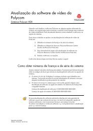
The <strong>MGC</strong>-<strong>50</strong>/<strong>100</strong> is shipped with a dongle installed on COM1 of the rear panel. The<br />
<strong>MGC</strong>-<strong>25</strong> is shipped with a dongle installed on parallel port of the rear panel.<br />
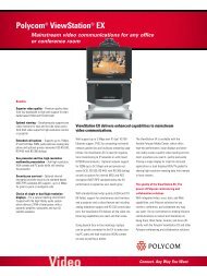
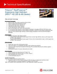
To verify if you have a dongle you are required to inspect the rear panel of the MCU as<br />
shown in Figure 1. The dongle label also includes the dongle serial number.<br />
Figure 1: MCU-<strong>100</strong> & MCU-<strong>25</strong> rear panels and their dongles<br />
11
<strong>MGC</strong> Release Notes - Version 7.5<br />
12<br />
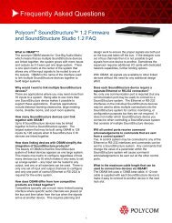
Figure 2: MCU+ <strong>50</strong> rear panel and Dongle location<br />
MOUSE<br />
KEYBOARD<br />
ALARMS<br />
The Dongle is backward compatible with current or previous <strong>MGC</strong> Manager versions.<br />
Dongle Upgrade Instructions<br />
LAN<br />
VGA<br />
COM2<br />
COM1<br />
R<br />
POLYCOM<br />
WARNING<br />
Product warranty will<br />
be void if seal label is<br />
removed or damaged.<br />
For a major version, such as upgrading from version 5.xx, 6.xx and 7.xx, a new dongle file<br />
must be loaded onto the MCU. To acquire the new dongle file, access the <strong>Polycom</strong><br />
Resource Center (“Downloading the Dongle File” on page 14) or contact your next level of<br />
support. Version 7.5 requires a new dongle file, and this file should be loaded prior to the<br />
upgrade.<br />
<strong>MGC</strong>-<strong>50</strong>/<strong>MGC</strong>-<strong>100</strong><br />
• Check the serial number of the dongle currently installed on the MCU (on the Dongle,<br />
a white label either on the face or side lists the Serial No.); right-click the MCU icon,<br />
and then click Dongle Information.<br />
The Dongle Information dialog box opens, displaying the dongle's serial number and<br />
the current MCU version.<br />
The serial number displayed in the Dongle Information dialog box should match the<br />
serial number of dongle as it appears in the name of the file sent to you (usually via<br />
e-mail). If the numbers do not match, do not proceed with the upgrade process and<br />
contact support.
Software Upgrade Procedure<br />
<strong>MGC</strong>-<strong>25</strong><br />
• Before you upgrade the dongle, please check and record the assignment between the<br />
ISDN Network Service and ISDN Network card.<br />
• Check the serial number of the dongle currently installed on the MCU; right-click the<br />
MCU icon, and then click System Configuration.<br />
The serial number displayed in the System Configuration dialog box should match the<br />
serial number of dongle as it appears in the name of the file sent to you (usually via<br />
13
<strong>MGC</strong> Release Notes - Version 7.5<br />
Downloading the Dongle File<br />
14<br />
e-mail). If the numbers do not match, do not proceed with the upgrade process and<br />
contact support.<br />
Prior to accessing the <strong>Polycom</strong> Resource Center Web site, retrieve from the MCU the<br />
system serial number.<br />
• The MCU-<strong>25</strong>/<strong>50</strong>/<strong>100</strong> have a <strong>Polycom</strong> label with a Serial No. fixed on the rear panel.<br />
To retrieve the Dongle File from a <strong>Polycom</strong> Web Site:<br />
Access the <strong>Polycom</strong> Resource Center web site http://extranet.polycom.com/csnprod/<br />
signon.html.<br />
User ID and Password are required to access this site. If you do not have a User ID or<br />
Password, please refer to your next level of support.<br />
3. Enter your User ID and Password and click Sign In.<br />
The Welcome to the <strong>Polycom</strong> Resource Center window appears.<br />
4. Click <strong>MGC</strong> Product Activation.<br />
The <strong>MGC</strong> Dongle Upgrade File window opens.<br />
5. Enter the System Serial Number and Dongle Serial Number.
6. Click Download.<br />
Save the new dongle file.<br />
Installing the Dongle File<br />
7. Click OK when Download is complete.<br />
Software Upgrade Procedure<br />
When the following error message appears: “No Maintenance Agreement Found/<br />
<strong>MGC</strong> Serial Number not Found”, please contact your next level of support.<br />
To Upgrade the Dongle:<br />
1. Connect to the MCU.<br />
2. Right-click the MCU icon, click MCU Utils, and then click Send Configuration File.<br />
The Open dialog box opens.<br />
3. Select the file .don from its location on your PC’s hard disk, and then click<br />
Open.<br />
The dongle is being upgraded.<br />
4. Reset the MCU.<br />
5. Connect to the MCU and verify that the dongle information was updated; right-click<br />
the MCU icon, and then click Dongle Information.<br />
The new version number should be listed in the MCU Version box.<br />
15
<strong>MGC</strong> Release Notes - Version 7.5<br />
<strong>MGC</strong> Unit Software Upgrade Procedure<br />
16<br />
You can run the installation from the CD, or you can copy the files to your hard drive, and<br />
then select the hard drive/directory as the source files path.<br />
Before upgrading the MCU software version:<br />
• If you do not have a dongle installed on your MCU, you must install it before upgrading to<br />
version 7.X.X. For more information, please contact Support.<br />
• A new dongle file must be loaded to the MCU to upgrade from version 5.XX or 6.XX to<br />
version 7.X.X.<br />
• Backup your configuration, including all Message Services.<br />
• It is important to back up all reservations in the MCU. This is to safeguard against<br />
reservations being lost. However, reservations backups can only be used with the same<br />
version for which backups were created.<br />
Upgrading from a Version using Password for Entry Queue Routing<br />
Version 7.5 uses Numeric ID as the routing method from Entry Queues to destination<br />
conferences. If your current version uses conference or chairperson password for routing<br />
from Entry Queues to destination conferences, when upgrading to Version 7.5, you must<br />
modify the system.cfg file included in the software kit.<br />
To upgrade the MCU version:<br />
1. Download the MCU software to the MCU. For more details, see “<strong>MGC</strong> Unit Software<br />
Upgrade Procedure”.<br />
Entry Queue Password routing mode is required to run PCS version 7.0.0.<br />
2. To route participants from the Entry Queue to the destination conference using the<br />
conference or chairperson password, you must modify the system.cfg file included in<br />
the software kit:<br />
a. Open the system.cfg file located in the MCU software folder.<br />
b. In the GREET AND GUIDE/IVR section, change the value of<br />
QUICK_LOG_IN_VIA_ENTRY_QUEUE flag to YES.<br />
c. Optional. To assign the same Numeric ID to different non concurrent<br />
conferences, in the GENERAL section change the value of<br />
RESERVATION_CONFERENCE_ID_UNIQUE to NO.<br />
d. Save the file.<br />
3. Send the “system.cfg” file to the MCU (MCU Utils -> Send File).<br />
4. Reset the MCU.<br />
5. Install the <strong>MGC</strong> Manager application Version 7.5.<br />
6. In the <strong>MGC</strong> Manager application, list the IVR/Entry Queue Message Services.<br />
7. For each listed Entry Queue Service, assign the appropriate voice messages in the new<br />
Conference ID tab.
Software Upgrade Procedure<br />
Upgrading from a Version using Numeric ID for Entry Queue Routing<br />
Version 7.5 uses Numeric ID as the routing method from Entry Queues to destination<br />
conferences. If your current version uses Numeric ID for routing from Entry Queues to<br />
destination conferences (version 6.x and higher), no change in the system.cfg file is<br />
required.<br />
To upgrade the MCU version:<br />
1. Download the MCU software to the MCU. For more details, see “<strong>MGC</strong> Unit Software<br />
Upgrade Procedure”.<br />
2. Send the “system.cfg” file included in the software kit to the MCU (MCU Utils -><br />
Send File).<br />
3. Reset the MCU.<br />
Removal of Redundant Configuration Files<br />
With initial <strong>MGC</strong> version installations, it is possible that the MCU was subject to version<br />
downgrades. In order to ensure smooth <strong>MGC</strong> version upgrade (if the MCU was subject to a<br />
downgrade), restore reservations, meeting rooms and card configurations prior to manually<br />
removing specific configuration files. Please contact <strong>Polycom</strong> Support for further<br />
instructions.<br />
Downloading the Software to the MCU<br />
To install a software update on the MCU:<br />
1. On the File menu, click Download MCU Software.<br />
Alternatively, right-click the MCU icon, click MCU Utils, and then click Download<br />
MCU Software.<br />
The Logon dialog box opens.<br />
The Login Name and Password of the currently logged in operator are entered by<br />
default. If required, enter another login name and password.<br />
17
<strong>MGC</strong> Release Notes - Version 7.5<br />
18<br />
2. Click OK.<br />
The Software Installation dialog box opens.<br />
The MCU software will be installed on each listed MCU.<br />
3. Select the Install Default Services check box to download the default IVR Service,<br />
Entry Queue Service, and Gateway Service. The default IVR Service is in English and<br />
is named IVR70. The default Entry Queue Service is in English and is named EQ70.<br />
You can manually install the default English IVR Service and Entry Queue Service or<br />
the English and Spanish IVR and Entry Queue Services. For more information, see<br />
“Installing the <strong>MGC</strong> Manager Software” on page 19.<br />
4. You can download software to all MCUs listed in the MCU List in one operation. If the<br />
list is not complete, you can add MCUs to the list by clicking the Add MCU button.<br />
To avoid downloading the software to an MCU, remove the MCU from the list by<br />
selecting the MCU Name, and then clicking the Remove MCU button. For more<br />
details, see the <strong>MGC</strong> Administrator’s Guide, Chapter 2.<br />
5. In the Enter path to source files box, type the full path to the folder containing the<br />
software version. Alternatively, click the Browse button and use standard Windows<br />
techniques to select the Folder containing the software. If the folder is named<br />
Vaaa.bbb, where aaa is the <strong>MGC</strong> Manager version number, and bbb is the MCU<br />
version number.<br />
You need to select the folder containing the latest version number, and not the sub-folder<br />
labeled Disk 1.<br />
6. Click OK.<br />
The software version’s path is displayed in the Enter path to source files box.<br />
7. Click the Install button to start the installation procedure.<br />
• When you upgrade the new software, the existing reservation files are automatically<br />
restored and converted to the new version format. It is essential to back up reservations<br />
using the new version format.<br />
• When you upgrade the MCU’s software, the existing card configuration files are<br />
automatically restored.<br />
• After the completion of the upgrade process, you need to manually update the existing<br />
Entry Queue Services by adding the voice message files prompting for the conference<br />
Numeric ID, otherwise the participants are placed on hold and cannot move to the target<br />
conferences.<br />
8. Reset the MCU.<br />
Sometimes, an error message “No_Connection_With_Card” is displayed when the software<br />
download to the cards takes more than 420 seconds. In such a case, reset each of the cards<br />
manually.
Installing the <strong>MGC</strong> Manager Software<br />
Software Upgrade Procedure<br />
The <strong>MGC</strong> Manager software is Windows 95/98/NT/ME/2000/XP based software.<br />
After downloading the software from the FTP and unzipping the files:<br />
1. Open Windows Explorer and open the folder that contains the <strong>MGC</strong> Manager<br />
diskettes.<br />
2. Browse to Disk 1 and double-click the Setup.exe file.<br />
3. Follow the on-screen instructions to complete the installation procedure.<br />
Manual Installation of the Default Message Services<br />
When upgrading from versions 5.x, 6.0 and 6.0x, the upgrade kit includes new Message<br />
Services that can be automatically installed on the MCU during the software installation.<br />
You can also manually install the default Message Services at the end of the installation<br />
process.<br />
The software CD contains two types of IVR Services:<br />
• English<br />
• English and Spanish<br />
The Automatic installation of Message services during MCU software update<br />
automatically installs the English only Message Services. The manual installation<br />
process enables you to install the English and Spanish Message Services as well as the<br />
English only. When you install the English and Spanish IVR Service, two separate IVR<br />
Services are created on the MCU and the English IVR Service is automatically set as<br />
the default IVR Service.<br />
To restore the Default IVR Service:<br />
The default Message Services are installed using the Restore Configuration utility.<br />
1. Right-click the MCU icon, click MCU Utils, and then click Restore Configuration.<br />
2. Enter the path to the folder containing the configuration files to be installed, or click<br />
the Browse button to locate them.<br />
3. From the Version 7.5 software folder, select the English V7 IVR or the English and<br />
Spanish V7 IVR folder, according to the required Message Service, and click OK.<br />
The system returns to the Restore dialog box.<br />
4. Click OK to continue.<br />
5. Click the Select All button.<br />
6. Click OK to install the default Message Services on the MCU.<br />
7. At the end of the Restore process, a message is displayed indicating that the MCU<br />
must be reset to be able to use the new Message Services.<br />
8. Click OK and reset the MCU.<br />
19
<strong>MGC</strong> Release Notes - Version 7.5<br />
Updating the Entry Queue Services<br />
20<br />
When upgrading from Version 5.x to Version 7.5 you need to update the Entry Queue<br />
Service to include the appropriate voice messages.<br />
To update the Entry Queue Service:<br />
1. Expand the IVR Message Services list (under the MCU Configuration list).<br />
2. Right-click the icon of Entry Queue Service to update (an Entry Queue Service that<br />
was defined in version 5.x), and then click Properties.<br />
The Entry Queue Message Service - General dialog box opens.<br />
3. Click the Conference ID/Password tab.<br />
4. In the Entry Queue Message Service - Conference ID/Password dialog box, assign the<br />
following voice messages:<br />
— Using Conference Password for Entry Queue Routing (Version 5.x mode):<br />
• Request Conference ID/Password: CONFPASS.ACA<br />
• Join Failure Message: CONFRTRY.ACA<br />
These files are located in the <strong>MGC</strong> software kit (as part of the default IVR Service<br />
for Version 7.5), in the following path:<br />
<strong>MGC</strong><strong>50</strong>-<strong>100</strong> Version 7.5\<strong>MGC</strong> SW CD Ver 7.5\IVR\Default Services\English V7<br />
IVR\msg\LANG70\NID\NUMID.<br />
— Using Conference Numeric ID for Entry Queue Routing:<br />
• Request Conference ID/Password: CNFIDRQS.ACA<br />
• Join Failure Message: CNFIDFL.ACA<br />
These voice messages are located in the <strong>MGC</strong> software kit (as part of the default<br />
IVR Service for Version 7.5).<br />
5. Click OK to save the changes.
Detailed Description - Video<br />
Detailed Description - Video<br />
Video Support for Start Conference requires Chairperson<br />
Detailed Description<br />
Audio and Video conferences support the Start Conference requires Chairperson option.<br />
Versions 7.0 and previous, Audio Only conferences supported the Start Conference<br />
requires Chairperson option. Version 7.01 supported phase 1 of the feature for video<br />
conferences.<br />
In version 7.5, when the conference requires a chairperson, Audio or Video conference<br />
participants are placed on hold when they connect to the conference before the chairperson<br />
and hear background music.<br />
Set the system.cfg flag: WAIT_FOR_CHAIR_VIDEO_TYPE_NEW=YES (default = NO)<br />
Based on the Flags settings, two types of behavior are possible:<br />
• NO; The participants can view each other and their audio is muted, till the chairperson<br />
joins the conference.<br />
• YES; When placed on hold, connected participants view the Welcome slide and hear<br />
background music, till the chairperson joins the conference.<br />
SIP participants cannot view the Welcome slide.<br />
Figure 3: Setting tab with Start conf Requires Chairperson checkbox<br />
21
<strong>MGC</strong> Release Notes - Version 7.5<br />
22<br />
Start Conference Requires Chairperson guidelines:<br />
• The conference must be defined with an IVR service. The IVR service must also<br />
include a video slide.<br />
• An 'Entry Tone' is not played for the participants waiting for the chairperson to arrive.<br />
The ‘entry tone’ is only heard when the chairperson is already in the conference.<br />
• The conference time-out (20 minutes) activates if the chairperson fails to attend the<br />
conference.<br />
• The operator cannot enable or cancel the Start Conference Requires Chairperson<br />
option while the conference is on-going.<br />
• A participant accessing the conference by using the “attended” Entry Queue, is guided<br />
to the conference but hears music (audio conference) or views the welcome slide<br />
(video conference) when the chairperson has not yet entered the conference.
Detailed Description - General<br />
Network Time Protocol (NTP) for XPEK Systems<br />
Detailed Description<br />
Detailed Description - General<br />
The Network Time Protocol (NTP) on XPEK systems allows the MCU to synchronize the<br />
internal MCU control unit’s clock with an external NTP server. Accurate time calculation is<br />
essential for cascaded or recurring conferences.<br />
The time synchronization protocol used in <strong>MGC</strong> version 7.5 is SNTP (Simple Network<br />
Time Protocol), a version of the NTP protocol used by Microsoft’s W32Time Service. NTP<br />
servers use the time-zone independent Universal Time Coordinated (UTC) standard to<br />
synchronize networked computers. UTC is the current official standard that is based on an<br />
atomic clock and ensures uniform time calculation for networks.<br />
To synchronize MCU time with the NTP Server:<br />
1. Right-click the MCU icon and click MCU Time.<br />
23
<strong>MGC</strong> Release Notes - Version 7.5<br />
24<br />
The MCU GMT Time dialog box opens.<br />
You cannot set the MCU’s time or connect to the NTP server, when there are On Going<br />
conferences on the bridge.<br />
2. In the MCU GMT Offset box, enter the time difference between the MCU Local Time<br />
and MCU GMT Time.<br />
3. Select the Use NTP Server check box, and enter the IP address of the NTP server.<br />
4. Click OK.<br />
NTP Server synchronization may take up to an hour. All time-related settings, such as<br />
the scheduled Starting Time of Reservations, are adjusted.
Secure Socket Layer (SSL)<br />
Detailed Description<br />
Detailed Description - General<br />
SSL (Secure Socket Layer) enables secure HTTP connection on MCU’s with XPEK<br />
Operating Systems with the <strong>MGC</strong> Manager, WebCommander and <strong>MGC</strong> API applications.<br />
SSL Certificate is required to enable SSL-level security for the MCU’s connection to<br />
external applications. SSL uses a third party, that is the Certificate Authority, to identify<br />
HTTP transactions and secure them using the HTTPS protocol.<br />
The SSL certificate must be obtained on first connection to the MCU.<br />
To obtain the SSL certificate:<br />
1. Connect to the MCU.<br />
2. Right-click the unit’s icon or name, and then click Create SSL Certificate Request.<br />
The dialog box opens where you can enter data for the request and apply.<br />
3. Fill in the following information:<br />
Table 2: SSL Certificate Request - Required Information<br />
Field Description<br />
Country Enter any 2 letter code for the country name.<br />
State or Province Enter the full name of the state or province.<br />
Locality Enter the full name of the town/city/location.<br />
Organization Enter the full name of your organization for<br />
which the certificate will be issued.<br />
Organizational Unit Enter the full name of the unit (group or division)<br />
for which the certificate will be issued.<br />
Common Name<br />
(DNS/IP)<br />
Enter the DNS or the IP address of the MCU.<br />
Enter complete information, as all fields are mandatory for the request.<br />
<strong>25</strong>
<strong>MGC</strong> Release Notes - Version 7.5<br />
26<br />
4. Click Apply.<br />
The new certificate request appears in the details box.<br />
5. Click Copy, then click Close.<br />
Alternatively, for a previously defined MCU for which SSL has been obtained before,<br />
click Get to get the latest certificate request from the MCU.<br />
6. In the browser, access your preferred certificate authority (for example, http://<br />
www.thawte.com and select from the quick login box: Certificate Status), paste the<br />
certificate request from MCU and submit.<br />
The authority issues the SSL certificate, and sends the certificate to you by E-mail.<br />
7. When the E-mail with the certificate arrives from the authority, select the text and click<br />
Copy.<br />
8. Back in the <strong>MGC</strong> Manager application, right-click the MCU’s icon and click Send<br />
SSL Certificate.<br />
The Send SSL Certificate dialog box opens.
9. Paste the certificate’s text in the Send SSL certificate window.<br />
10. Click Send.<br />
The MCU validates the certificate.<br />
— If the certificate is not valid, the following message appears:<br />
Detailed Description - General<br />
— If the certificate matches the private key, and the task is completed, a message<br />
informs you that the certificate was created successfully.<br />
11. Reset the MCU.<br />
The system has access to the SSL-secured port 443.<br />
27
<strong>MGC</strong> Release Notes - Version 7.5<br />
28<br />
To enable a Mandatory and Secure connection for the MCU:<br />
1. Before connecting the MCU, right-click the MCU icon and click MCU Utils, then<br />
click Edit “system.cfg”.<br />
The SysConfig dialog box opens.<br />
2. In the GENERAL section, set the following flags to:<br />
— SECURED_PORT_MANDATORY_FOR_API=YES<br />
— SECURED_PORT_MANDATORY_FOR_FILE=YES<br />
— PREFERRED_SECURED_PORT=443<br />
3. Click OK and then reset the MCU.<br />
4. Right-click the MCU icon and then click Properties.<br />
Do not connect to the MCU. When you right-click the MCU, the MCU should be<br />
disconnected and the icon appear grey.<br />
5.<br />
The Properties dialog box opens.<br />
Click Advanced.<br />
6. Select the Secured check box to enable mandatory security.<br />
7. Ensure that the Automatic Discovery option is deactivated (clear the check box).<br />
8. The Port Number box is enabled, enter port 443 as the Port Number.<br />
9. Click OK.<br />
10. Connect to the MCU.<br />
When reconnected, the MCU uses the secured port.<br />
After reconnecting, it is recommended to change the login password.
Detailed Description - General<br />
— The HTTPS protocol is indicated in the Connections list Protocol column under<br />
the MCU Configuration icon. Port 443 and the Secured (the lock) icon are<br />
indicated in the <strong>MGC</strong> Manager window’s status bar.<br />
29
<strong>MGC</strong> Release Notes - Version 7.5<br />
H.239/People+Content Star Cascading<br />
Detailed Description<br />
30<br />
H.239/People+Content Star Cascading is available with mixed H.320 and H.323 Video<br />
Switching conferences.<br />
In <strong>MGC</strong> version 7.0, H.239/People+Content Star Cascading was only available in an IP<br />
Video Switching environment.<br />
All the conferences in the Star Cascading topology must have the same settings for the<br />
conference: line rate, audio algorithm, Video Parameters (Video Protocol, Video Format,<br />
Video Frame Rate, Annexes, and ProMotion) and other conferencing features such as<br />
Encryption.<br />
Highlights:<br />
• One central MCU is required in a conference. A slave MCU can only be cascaded to<br />
the main MCU. A Slave MCU cannot be cascaded with other slave MCUs.<br />
• Only two cascade options - "Master" and "Slave" - is available in H.320 H.239/ P+C<br />
cascade. There will be no "Auto" cascade mode like in regular H.320 cascade.<br />
• IVR is supported. However, if Node Type in the Participant Properties - Advanced is<br />
set to MCU, no IVR service is available.<br />
• Encryption is supported.<br />
• H.243 site names for H.320 are supported<br />
H.320 cascade links use the H.239 protocol and not <strong>Polycom</strong> P+C protocol, as in IP<br />
cascaded conferences.<br />
H.239 can only be implemented when in the system.cfg: H.239=YES.
Ad Hoc Auto Cascade<br />
Detailed Description<br />
Detailed Description - General<br />
The Auto Cascade feature enables automatic cascading of conferences. Both audio only<br />
and video conferences can be cascaded.<br />
The automatic cascading of conferences is beneficial in distributed MCU environment,<br />
when MCUs are installed in different locations. A maximum of six conferences can be<br />
Auto Cascaded into one conference. The MCU network can support multiple Auto<br />
Cascaded conferences simultaneously.<br />
The cascading is performed by an Ad Hoc Cascade component in the WebCommander<br />
Professional which monitors the MCUs. When the Ad Hoc Cascade component finds that<br />
two or more MCUs are running a conference with the same Conference Numeric ID, it<br />
checks if the conferences are already cascaded by looking for a cascading link between the<br />
conferences. If there are no cascading links, conferences are automatically connected using<br />
pre-defined cascading links. If at a later stage the Ad Hoc Cascade component finds an<br />
additional MCU running a conference with the same Numeric ID, it adds the conference to<br />
the cascaded conferences.<br />
Set up identical Ad Hoc Entry Queues and Profiles on each MCU, so that the cascaded<br />
conferences will have the same properties.<br />
To use the Auto Cascade feature, the system.cfg flag<br />
QUICK_LOGIN_VIA_ENTRY_QUEUE must be set to NO on all MCUs, that is, the<br />
Conference Numeric ID routing mode must be used. This flag is located in the GREET<br />
AND GUIDE/IVR section of the system.cfg file.<br />
31
<strong>MGC</strong> Release Notes - Version 7.5<br />
32<br />
Defining Auto Cascading Entry Queues<br />
To eliminate IVR prompts when Auto Cascade links are created, you must set up Auto<br />
Cascade Entry Queues on each MCU.<br />
1. In the Entry Queue Properties dialog box, select the Cascade check box.<br />
2. Enter a value in the Numeric ID field. The Numeric ID must be identical in the Auto<br />
Cascading Entry Queues of all the MCUs.<br />
3. Leave the Ad Hoc check box cleared.<br />
4. Proceed to configure the Entry Queue as for any other Entry Queue.<br />
Implementation of Chairperson DTMF features<br />
The following chairperson DTMF actions are implemented across the MCUs:<br />
• Mute all but me and unmute<br />
• Terminate the conference<br />
• Place the conference on hold and release the conference from being placed on hold<br />
• Lock and unlock the conference<br />
• Secure the conference and release a secured conference<br />
• Wait for the Chairperson<br />
Chairperson Conference Activation<br />
If chairperson activation is enabled in the Auto Cascade configuration in the <strong>MGC</strong><br />
WebCommander Server Manager, then the cascaded conference may implement the “Start<br />
only when the chairperson connects”, and “Terminate conference after the chairperson<br />
exits” features, provided these options are selected in the individual conferences. If the
Limitations<br />
Detailed Description - General<br />
“Start only when the chairperson connects” option is implemented, participants in all<br />
conferences will be placed on hold until a chairperson joins one of the conferences. If the<br />
“Terminate conference after the chairperson exits” option is implemented, all conferences<br />
will be terminated when there is no longer a chairperson connected to a conference.<br />
Terminating a Cascading Conference<br />
The system will terminate a slave conference when it no longer has any live participants,<br />
and will terminate the master conference when it no longer has any live participants itself<br />
and has no slave conferences with live participants.<br />
Monitoring Auto Cascaded Conference Links<br />
The links between Auto Cascaded conferences can be monitored in both the <strong>MGC</strong> Manager<br />
and the <strong>MGC</strong> WebCommander. The important links to monitor are the dial-out link<br />
participants.<br />
Figure 1-1 shows an example of monitoring an Auto Cascaded conference in the <strong>MGC</strong><br />
Manager.<br />
Figure 1-1: Monitoring an Auto Cascade conference<br />
The Link Participant Names<br />
The dial-out link participant name will be as follows:<br />
LinkTo[ConferenceType(Master/Slave)]_[Target MCU IP]_<br />
[Primary or Secondary connection (0/1)_[Link Number (01..99)]<br />
For example, the master conference link to slave3 may be called:<br />
LinkToSlave_11.11.11.11_0_03<br />
Dial-in link participants will have a visual name of the following format after they are<br />
moved from the Entry Queue to the conference:<br />
LinkTo[ConferenceType(Master/Slave)]_[Link Number (01..99)]<br />
For example, the dial-in link from a slave conference may have the visual name:<br />
LinkToMaster_01<br />
• In Continuous Presence conferences, the layout must be set to full screen.<br />
• The <strong>MGC</strong> Manager and WebCommander monitoring is per MCU. There is no GUI to<br />
display cascaded conferences across multiple MCUs as one conference.<br />
• The following chairperson actions are implemented per MCU: Voting, Question and<br />
Answers, Replay Roll Call, Change password and Operator assistance.<br />
• For H.263 4CIF and H.264 Continuous Presence conferences, the link will be defined<br />
as H.263 CIF.<br />
• The Auto Cascade feature does not work with H.239/People + Content.<br />
33
<strong>MGC</strong> Release Notes - Version 7.5<br />
Faulty Participant in Red<br />
Detailed Description<br />
34<br />
A “Faulty” participant connected to a conference has their background color marked red for<br />
greater visibility in the <strong>MGC</strong> Manager monitoring pane.<br />
All participants that have a problem with their connection and require operator assistance<br />
are marked and highlighted in a red background color. The cause of the problem is marked<br />
in the Connection column.<br />
To mark faulty participants in red in the <strong>MGC</strong> Manager:<br />
1. From the Options menu, select Mark Faulty Participants in Red.<br />
A check mark appears before Mark Faulty Participants in Red.<br />
2. In the <strong>MGC</strong> Manager all participants requiring operator assistance are highlighted in<br />
red, as shown in the Monitor pane.
HTTP File Transfer Mode<br />
Detailed Description<br />
Transfer of files using HTTP can be performed by the <strong>MGC</strong> Manager.<br />
Detailed Description - General<br />
HTTP can replace FTP, to solve Firewall issues, PSOS limitations in the FTP mode and<br />
address security issues occurring in FTP. The user can select either the HTTP or FTP mode<br />
of operation from the Options menu. When selecting FTP mode either an Active or Passive<br />
FTP connection can be enabled.<br />
To enable HTTP Connection mode from the Options menu:<br />
1. In the Options menu, select FTP Configurations.<br />
The FTP Configurations dialog box opens.<br />
2. Click Use HTTP Connection.<br />
Select Use FTP Connection and click Enable Passive FTP Connection to enable<br />
the Passive FTP mode.<br />
When the Passive FTP connection is enabled, the client opens the primary<br />
connection to the server. The server acknowledges a connection request, and<br />
informs the client on which port to connect to the secondary connection. The client<br />
opens the secondary connection according to the port supplied by the server.<br />
35
<strong>MGC</strong> Release Notes - Version 7.5<br />
Same Layout Option in Video Switching Conferences<br />
36<br />
In version 7.5, when the Same Layout option is checked, the speaker in his monitor views<br />
himself instead of the previous speaker.
Direct IP Dial-in<br />
Detailed Description<br />
Direct End Point Dialing<br />
Detailed Description - General<br />
Direct IP MCU Dial-in modes: IP address & extension string. Enables internet IP calls to a<br />
MCU that functions as a Firewall Gateway (MCU is inside the Firewall zone).<br />
The MCU supports two new MCU Dial-in strings:<br />
• Direct End Point Dialing<br />
• IP to ISDN Gateway Call<br />
The Direct End Point Dialing method enables undefined dial-in participants to connect to<br />
conferences without a gatekeeper being used for address resolution. The Direct End Point<br />
Dialing method can be implemented with or without a Gatekeeper. When a Gatekeeper is<br />
present it should be set to a Direct Call Policy configuration.<br />
Conference dial-in can be achieved using one of the following methods:<br />
• FX endpoints support the delimiter "," and not "##"<br />
• H.323 card’s IP address##conf NID (for example: 172.22.190.162##1234)<br />
• When the endpoint has extension capabilities available, list the H.323 card’s IP<br />
address in the destination field and conference NID in the extension field. For<br />
example: 172.22.190.162 as the call address and 1234 (conference NID) in the<br />
Extension field, or 172.22.190.162 as destination IPaddress and 3116##1234 (i.e. ED<br />
NID - 3116, Conf. NID - 1234) in the endpoint’s Extension field.<br />
• In case the endpoint has the extension capabilities use H.323 card’s IP address as the<br />
destination address and EQ NID##conf NID in the extension field. For example:<br />
Test result summary for Meeting Rooms and On-Going conferences:<br />
IP + Extension is supported on VSX3000/7000/8000, V<strong>50</strong>0, FX, and VS endpoints.<br />
IP##NID is supported on VSX3000/7000/8000, V<strong>50</strong>0, FX, VS, Sony, and PVX endpoints.<br />
Test result summary for Entry Queues:<br />
IP + Extension is supported on VSX3000/7000/8000, V<strong>50</strong>0, and FX endpoints.<br />
IP## EQNID##NID is supported on VSX3000/7000/8000, V<strong>50</strong>0, FX, and PVX endpoints.<br />
IP to ISDN Gateway Call (without Gatekeeper)<br />
On a network without a Gatekeeper, you can use the following IP to ISDN sting to dial-in<br />
to the MCU:<br />
• IP address of H.323 card##gateway prefix*ISDN number of remote ISDN endpoint.<br />
For example (172.21.11.14##63*0141321800).<br />
37
<strong>MGC</strong> Release Notes - Version 7.5<br />
SIP Factory<br />
Detailed Description<br />
38<br />
SIP Factory is a new conferencing entity that enables SIP endpoints to create an arbitrary<br />
number of ad hoc conferences and automatically connect to the new conferences.<br />
When the Sip Factory is created, using SIP call control means, a globally routed<br />
Conference Factory URI can be allocated and published. When a SIP endpoint calls this<br />
URI, and the call is established successfully, a new conference is automatically created and<br />
the endpoint joins the conference. The conference automatically ends when the conference<br />
creator leaves the conference. All other participants are invited to the conference using the<br />
SIP REFER method.<br />
To create a SIP Factory:<br />
A conference Profile must be defined in the MCU before creating a SIP Factory. The Profile<br />
should be set to Auto Terminate when the Chairperson exits the conference.<br />
1. Expand the MCU tree.<br />
2. Right-click the Meeting Rooms, Entry Queues & SIP Factories icon and then click<br />
New SIP Factory.<br />
The SIP Factory dialog box opens.<br />
3. Define the following parameters:<br />
— Name - Enter the SIP Factory Name. This is the name that will be used as part of<br />
the URI (together with the domain name) dialed by the SIP endpoint to initiate the<br />
conference.
Detailed Description - General<br />
— Profile - select the conference Profile from the list of Profiles defined in the<br />
MCU. The new conference will be created using the parameters defined in the<br />
Profile.<br />
— Automatic Connection - Select this check box to immediately accept the<br />
conference creator endpoint to the conference. If cleared, the endpoint will be<br />
redirected to the conference and then connected.<br />
4. Click OK.<br />
The New SIP Factory is added to the list.<br />
Enabling the Registration of the SIP Factories with the SIP Proxy:<br />
The SIP Factory URI must be registered with the SIP server to enable routing of calls to the<br />
SIP Factory.<br />
To register the SIP Factory, the registration option must be enabled in the IP Network<br />
Service - SIP dialog box.<br />
In the Register section, select Entry Queues & SIP Factories.<br />
Connecting to the SIP Factory<br />
The conference initiator dials the SIP Factory URI and connects to an Ad-hoc conference.<br />
39
<strong>MGC</strong> Release Notes - Version 7.5<br />
Nortel Environment Flag Settings<br />
40<br />
The system automatically detects the Nortel environment and changes the working mode<br />
accordingly (no need to set the Nortel flag in the system.cfg).<br />
However, if you do not see video with the Nortel endpoints, the following system.cfg flags<br />
may be set:<br />
• IGNORE_STREAM_VIOLATION in the IP MISC FLAGS section<br />
Set this flag to YES, to connect the video channel of Nortel endpoints that send video<br />
at a line rate higher than the rate declared in the capabilities exchange. When set to<br />
NO, these endpoints will connect as Secondary.<br />
• SIP_USER_AGENT_FLOW_CONTROL_RATE in the SIP section.<br />
Set this flag to the following values: 8,64,128,<strong>25</strong>6,384,512,768.<br />
This flag indicates the line rates that should be requested from the Nortel endpoints to<br />
prevent video overflow (default values are: 64,128,192,<strong>25</strong>6,384,512,768).<br />
• If you have set the flow control rate to Nortel mode but your environment includes<br />
also <strong>Polycom</strong> endpoints that do not exceed the declared line rate and therefore should<br />
not be requested to send lower video rates, define the following flag to exclude them<br />
from the flow control mode:<br />
In the SIP section set the flag SIP_USER_AGENT_FLOW_CONTROL to<br />
POLYCOM.
Detailed Description - General<br />
<strong>MGC</strong>+ Predefined IP only Entry Queues and Meeting Rooms<br />
The <strong>MGC</strong>+ unit is shipped with two pre-defined IP Only Entry Queues and eight<br />
predefined Meeting Rooms as follows:<br />
• Entry Queue CP whose Numeric ID is 1111, and Video Session type is Continuous<br />
Presence, is used to access Meeting Rooms <strong>100</strong>0, 2000, 3000 and 4000.<br />
• Entry Queue VSW whose Numeric ID is 2222, and Video Session type is Video<br />
Switching, is used to access Meeting Rooms <strong>50</strong>00, 6000, 7000 and 8000.<br />
The Entry Queues and Meeting Rooms are set to line rate of 384 Kbps.<br />
Meeting Rooms <strong>100</strong>0, 2000, 3000 and 4000 are set to Continuos Presence mode. Meeting<br />
Rooms <strong>50</strong>00, 6000, 7000 and 8000 are set to Video Switching mode.<br />
Meeting Room names and Numeric IDs are identical. For example, Meeting Room 3000<br />
has the Numeric ID 3000.<br />
The Network Configuration wizard, which is activated when the MCU is installed in the<br />
site for the first time, enables you to reconfigure the IP Address of the IP cards, the IP<br />
address of the network entities and the default IP Network Service Prefix. To use the<br />
default Entry Queues and Meeting Rooms without modifying them, define the prefix as<br />
789.<br />
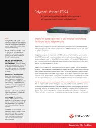
Two Entry Queue Services (one per Entry Queue) and one default IVR Service are also<br />
shipped with the system. When accessing an Entry Queue, the system displays a video slide<br />
indicating the numeric IDs of the predefined Meeting Rooms that can be accessed from this<br />
Entry Queue.<br />
Figure 2: Entry Queue Video Slide<br />
41
<strong>MGC</strong> Release Notes - Version 7.5<br />
42<br />
When joining a Meeting Room, the system displays a video slide indicating the operations<br />
that can be performed from the participant’s endpoint and the DTMF code that must be<br />
used to activate each operation.<br />
Figure 3: Meeting Room Video Slide
Corrections, Pending Issues and Limitations<br />
Corrections between Versions V.7.0.2 and V.7.5<br />
Table 3: Corrections between Versions V.7.0.2 and V.7.5<br />
Corrections, Pending Issues and Limitations<br />
#. Category Description ID# Remarks<br />
1. Audio+ In an Encrypted VS conference with 96<br />
Dial-out and 96 Dial-in participants, the<br />
Audio+ cards crashed.<br />
2. Cascade Video Switching, H.261 Fixed, 384Kbps<br />
and H239/P+C defined conferences<br />
may suffer from bad video quality.<br />
3. CP In a CP conference with a PSTN<br />
participant, the speaker indication<br />
disappears.<br />
4. General When the <strong>MGC</strong> Manager uses port 80<br />
to connect to the <strong>MGC</strong> unit, the <strong>MGC</strong><br />
Manager may disconnect from the<br />
<strong>MGC</strong> unit (Bad connection status).<br />
5. H.239 When sending Content from two<br />
endpoints at the same time (within the<br />
same second), one endpoint will not be<br />
able to send Content again.<br />
6. H.239 Connecting 12 H.239 participants to an<br />
MG323 board causes the card to crash.<br />
7. Meeting Rooms When a conference is defined as a<br />
Meeting Room, it takes over two<br />
minutes to receive any indication from<br />
<strong>MGC</strong> Manager.<br />
8. <strong>MGC</strong> Manager Endpoints appear as “faulty connected”<br />
during the first seconds of connection.<br />
9. Microsoft During an On Going conference<br />
participants from a previous conference<br />
are listed.<br />
10. MPI When upgrading the MCU software<br />
from version 6.xx to version 7.0.X, on<br />
an MCU with two MPI cards, an<br />
exception may occur.<br />
20460<br />
20975<br />
20375<br />
20317<br />
20452<br />
20458<br />
21248<br />
20382<br />
21472<br />
19600<br />
43
<strong>MGC</strong> Release Notes - Version 7.5<br />
Corrections between Versions V.7.0.1 and V.7.0.2<br />
44<br />
Table 4: Corrections between Versions V.7.0.1 and V.7.0.2<br />
#. Category Description ID# Remarks<br />
1. Audio On an MCU with simultaneous<br />
conferences, audio can be heard from<br />
another conference.<br />
2. Audio When many participants are detected<br />
as having a Noisy Line, other<br />
participants cannot connect to the<br />
Audio+ card.<br />
3. Cascade In Cascaded Video Switching<br />
conferences with a leased line link<br />
inconsistent switching between<br />
speaker and participants can occur.<br />
4. Cascade In an ISDN Master-Slave cascading<br />
conference, if participants are<br />
connected to the conference before<br />
connecting the links between the<br />
conferences, the site names disappear<br />
after the speaker changes.<br />
5. Cascade In an ISDN Master-Slave cascading<br />
conference, if participants are<br />
connected to the conference before<br />
connecting the links between the<br />
conferences, it takes about a minute<br />
for a Tandberg endpoint to become the<br />
speaker.<br />
6. Cisco IP Phone<br />
endpoint<br />
No Audio or Video when using Cisco IP<br />
phone.<br />
7. CP In a H.264 conference, iPower set to a<br />
desktop mode causes video<br />
fragmentation.<br />
8. CP During a CP conference participants<br />
with long names disconnect.<br />
9. CP In a CP conference with 2x2 layout,<br />
video forcing is not implemented.<br />
10. Encryption In Encrypted conferences no<br />
resources available for Encrypted<br />
participants allocated on IP+ cards with<br />
HW version 4.22.<br />
11. External dB After resetting the server, the MCU<br />
stays in Major when there is an<br />
external Database connection.<br />
12. Falcon Falcon diagnostics cannot be used to<br />
test Audio+ cards.<br />
20071<br />
19424<br />
20161<br />
17373 Connect first the<br />
Cascading link.<br />
17390<br />
20566<br />
20557<br />
18483<br />
20515<br />
20570<br />
20498<br />
20778<br />
—
Table 4: Corrections between Versions V.7.0.1 and V.7.0.2<br />
13. Falcon The Falcon application crashes after<br />
downloading diagnostic traces on the<br />
<strong>MGC</strong>-<strong>25</strong>.<br />
Corrections, Pending Issues and Limitations<br />
#. Category Description ID# Remarks<br />
14. Falcon No Falcon diagnostics available on<br />
Video+ cards.<br />
15. General When the MCU is extremely loaded,<br />
conferences may terminate before<br />
their scheduled time (XPEK operating<br />
system only)<br />
16. General PictureTel Legacy endpoint cannot<br />
connect to On Going conferences.<br />
In the system.cfg, General section a<br />
new flag:<br />
TRADITIONAL_END_POINTS_MODE<br />
=NO has been added (default). Set this<br />
flag to YES, when using older<br />
PictureTel endpoints.<br />
17. General In the Participants Queue the operator<br />
cannot attend the next participant. The<br />
message "No Party in Participants<br />
Queue" appears.<br />
18. General Version default password and<br />
connectivity issues when upgrading:<br />
V.5 to V.6 & V.5 to V.7.<br />
19. General When an operator joins the<br />
conference, the conference<br />
terminates.<br />
20. H.239 In an IP conference Sony endpoints do<br />
not open the Content channel.<br />
21. H.239 After sending content in ISDN, the<br />
H.239 channel does not open.<br />
22. H.239 Slave conferences cannot receive<br />
content from the Master conference on<br />
the <strong>MGC</strong>-<strong>25</strong>.<br />
23. IP Alias names for IP participants<br />
increased to <strong>100</strong> characters.<br />
24. IVR When connecting a defined dial-out<br />
participant to a Meet Me Per<br />
conference with IVR that all its options<br />
are enabled, and the participant is first<br />
to connect, the participant hears the<br />
voice message (you are the first<br />
participant to connect), but does not<br />
hear the music that should follow the<br />
message.<br />
20469<br />
—<br />
19118<br />
19945 Set the<br />
system.cfg flag<br />
to YES.<br />
20141<br />
20283<br />
20511<br />
19673<br />
20565<br />
20649<br />
20481<br />
166<strong>25</strong><br />
45
<strong>MGC</strong> Release Notes - Version 7.5<br />
46<br />
Table 4: Corrections between Versions V.7.0.1 and V.7.0.2<br />
#. Category Description ID# Remarks<br />
<strong>25</strong>. <strong>MGC</strong> Manager When using MCU port <strong>50</strong>01,<br />
conference names are not displayed in<br />
the IP card properties.<br />
26. <strong>MGC</strong>-<strong>25</strong> When using the Fast Configuration<br />
Wizard, the <strong>MGC</strong> Manager crashes<br />
while configuring the ISDN Network<br />
Service.<br />
27. MPI Synchronization improvements on the<br />
RTS signal.<br />
28. MPI An MPI endpoint connected as Direct<br />
appear as dial-in the <strong>MGC</strong> Manager.<br />
29. MUX+ Connecting more than 15 ISDN H.239<br />
VSX endpoints to a conference may<br />
cause the MUX+40 card to crash.<br />
30. SIP During an Invite session the Session<br />
Description Protocol mutes the audio<br />
of the participant.<br />
31. SIP When dialing-in to an On Going<br />
conference the IP+48 card crashes.<br />
32. T1-CAS An exception occurs after a T1-CAS<br />
participant dial-in (Audio Only).<br />
33. T1-CAS During Audio Only conferences<br />
T1-CAS dial-out participants cannot<br />
connect.<br />
34. Video When moving a video muted<br />
participant, the participant is<br />
automatically unmuted after the move<br />
to the new conference<br />
20294<br />
20584<br />
—<br />
20371<br />
20427<br />
20545<br />
20528<br />
20599<br />
20561<br />
20246<br />
20<strong>25</strong>7<br />
20327
Corrections between Versions V.7.0 and V.7.0.1<br />
Table 5: Corrections between Versions V.7.0 and V.7.0.1<br />
Corrections, Pending Issues and Limitations<br />
#. Category Description ID# Remarks<br />
1. Ad Hoc<br />
conferencing<br />
During an Ad Hoc conference, when<br />
the chairperson presses DTMF code *3<br />
to invite a PSTN invitee, an Assert<br />
occurs on the system.<br />
2. Audio+ After 40 cycles of starting and<br />
terminating a conference that includes<br />
many participants, the Audio+96 card<br />
may crash.<br />
3. Cascading Error messages are displayed when<br />
cascading conferences run on <strong>MGC</strong><br />
MCU and Tandberg MCU.<br />
4. Cascading Occasionally, the IP+12 card crashes<br />
when IP participants connect to a<br />
cascading P+C/H.239 conference for<br />
longer than two hours.<br />
5. Cascading Asserts may occur when connecting<br />
cascading conferences in H.323.<br />
6. COP In a conference set to H.264, when<br />
endpoints connect the frame rate<br />
decreases.<br />
7. COP In a CoP conference disconnecting a<br />
participant, video loss (Video Out 0) to<br />
all conference participants may occur.<br />
8. CP In a H.263 conference, after changing<br />
layouts of participants and speaker no<br />
outgoing video stream is sent.<br />
9. CP A H.263, FECC conference with a line<br />
rate set to 786Kb may have a<br />
fragmentary video.<br />
10. CP With H.264 and XGA Video Format<br />
conference settings, the video+ card<br />
may crash.<br />
11. CP In an H.263 conference, after changing<br />
layouts of participants and speaker the<br />
Video card may crash.<br />
12. CP In a large Continuous Presence<br />
conference where the participants<br />
reside on more than one video card, the<br />
video layout background screen flashes<br />
(blue screen effect) when there is an<br />
exchange of speakers between the two<br />
video cards.<br />
14821<br />
19930<br />
13345<br />
17326<br />
19802<br />
19602 This is an<br />
endpoint issue<br />
and not the<br />
MCU’s<br />
19838<br />
19413<br />
19452<br />
19535<br />
19396<br />
14213<br />
47
<strong>MGC</strong> Release Notes - Version 7.5<br />
48<br />
Table 5: Corrections between Versions V.7.0 and V.7.0.1<br />
#. Category Description ID# Remarks<br />
13. H.323 An exception may occur when<br />
connecting more than 96 H.323<br />
participants in a blast dial-out<br />
conference.<br />
14. Lecture Mode -<br />
CP conference<br />
15. Lecture Mode -<br />
CP conference<br />
Incorrect speaker is displayed when the<br />
first participant that connects to the CP<br />
conference set to Lecture Mode,<br />
running on the Standard Video card, is<br />
muted and the second participant is<br />
unmuted. The first participant remains<br />
the speaker although second<br />
participant should have been selected<br />
as the speaker.<br />
No video when connecting a single<br />
participant to a CP conference set to<br />
Lecture Mode, running on the Standard<br />
Video card, and the selected layout is<br />
other than full screen.<br />
16. <strong>MGC</strong> Manager When creating a new Network Service,<br />
after adding 10 different Spans, the<br />
17. <strong>MGC</strong> Manager In the <strong>MGC</strong> Manager monitoring pane<br />
refresh problems may cause wrong<br />
endpoint status.<br />
18. <strong>MGC</strong> Manager No 'Faulty connection' indication in the<br />
<strong>MGC</strong> Manager application.<br />
19. Video A blue screen is displayed for 1-1.5<br />
seconds when the speaker changes in<br />
a conference with more than 10<br />
participants in Classic or Quad Views<br />
CP conference running on the Video+<br />
card.<br />
20. Video Conferences with 4CIF or higher Video<br />
Formats may encountered brief video<br />
interruptions.<br />
21. Video VSX endpoint connect as Secondary<br />
(audio only) when connecting via ISDN<br />
to a VSW conference set to Auto mode,<br />
as the endpoint uses encryption for the<br />
connection.<br />
22. Video<br />
Switching<br />
In a conference set to <strong>25</strong>6Kb line rate,<br />
connecting and disconnecting ISDN<br />
endpoints cause the MUX+ card to<br />
crash.<br />
23. XGA In a IP conference with the Video<br />
Format set to XGA, errors could occur<br />
when sending content.<br />
24. XPEK In certain instances the MCU does not<br />
accept valid IP addresses<br />
19887<br />
17571<br />
17571<br />
19939<br />
19860<br />
20194<br />
16032<br />
19462<br />
18991 This is an<br />
endpoint issue<br />
and not the<br />
MCU’s.<br />
19680<br />
19632<br />
19346
Version 7.5 Pending Issues<br />
Table 6: Pending Issues<br />
Corrections, Pending Issues and Limitations<br />
#. Category Description ID# Remarks<br />
1. Audio When using the G.729 audio algorithm,<br />
no audio available with VoIP or SIP<br />
phones.<br />
2. Cascade In an ISDN Master-Slave cascading<br />
conferences, if participants are<br />
connected to the conference before<br />
connecting the links between the<br />
conferences using blast dial-out,<br />
morphing occurs on some endpoints<br />
during the connection process.<br />
3. Cascade In Cascaded Video Switching<br />
conferences with an ISDN link, FECC<br />
occasionally does not work.<br />
4. Content All the participants Status becomes<br />
Faulty Connected when PVX endpoints<br />
send Content.<br />
5. COP When the first active participant is<br />
disconnected and the video of other<br />
participants is muted, participants view<br />
background colors.<br />
6. CP MCU status changes to Major for 30<br />
seconds when connecting 32 endpoints<br />
at a line rate of E1 to a CP conference.<br />
7. CP In a CP Quad Views conference with<br />
more than 12 H.264 participants, the<br />
frame rate may decrease.<br />
8. CP Fragmented Video can occur during<br />
speaker changes in CP H.264<br />
conferences.<br />
9. Database In the Participants database, when you<br />
Copy As a participant template and<br />
then modify this template without prior<br />
pasting the copied template, the system<br />
forces you to save the original template<br />
under a different name.<br />
10. Encryption In a Video Switching encrypted<br />
conference with more than 75<br />
participants and set to a 768KB line<br />
rate, the Audio+ card may crash.<br />
11. Falcon<br />
Diagnostic Tool<br />
12. Falcon<br />
Diagnostic Tool<br />
Long loop test may fail when running<br />
the diagnostic on the <strong>MGC</strong>-<strong>25</strong><br />
Falcon diagnostics sometimes cannot<br />
connect to the cards.<br />
20554<br />
20299<br />
21569<br />
19288<br />
20331<br />
20553<br />
21311<br />
21142 Save the<br />
participant under<br />
a new name, and<br />
then, if required,<br />
delete it from the<br />
database.<br />
19552<br />
20467<br />
21551<br />
49
<strong>MGC</strong> Release Notes - Version 7.5<br />
<strong>50</strong><br />
Table 6: Pending Issues (Continued)<br />
#. Category Description ID# Remarks<br />
13. FECC FECC does not work between an IP<br />
endpoint and an MPI (DTE) endpoint.<br />
14. FTP FTP service on XPEK may stop<br />
working, which affects system<br />
functions, such as prevent the Logger<br />
Diagnostic Files from opening, causing<br />
the <strong>MGC</strong> Manager application to close.<br />
15. Gatekeeper<br />
CON<br />
Gatekeeper CON (Conference On<br />
Demand) does not work with the<br />
<strong>MGC</strong>-<strong>25</strong>. With the <strong>MGC</strong>-<strong>50</strong>/<strong>MGC</strong>-<strong>100</strong>/<br />
<strong>MGC</strong>+ it works with asserts.<br />
16. Gateway When connecting conferences using<br />
the Gateway when you move a<br />
participant to and from a conference, no<br />
video is seen.<br />
17. Gateway When calling from H323 endpoint to an<br />
EQ placed on <strong>MGC</strong> V6 (used as an<br />
MCU) through <strong>MGC</strong> V7 (used as GW<br />
H323->H320), the call will fail.<br />
18. General When moving a participant from one<br />
conference to another, the “First to join”<br />
IVR message is heard twice.<br />
19. General The 'Auto_Redial' parameters in<br />
'confer.cfg' file are not updated.<br />
20. General Creating a conference with parameters<br />
"enable invite" and "encryption", the<br />
invitees are rejected.<br />
21. General SilenceIT algorithm does not<br />
automatically mute participants placing<br />
their line on hold, hence background<br />
music is played to the conference.<br />
22. H.264 In Video Switching conference set to<br />
H.264 and a line rate of 384Kbps, Sony<br />
endpoints connect as secondary.<br />
23. H.323 Connecting a service to a card during<br />
card download card results in card<br />
failure.<br />
20401<br />
20433 In the IP<br />
Terminal, enter<br />
restore_ftp. If<br />
the system<br />
displays an<br />
indication that<br />
the ftp cannot be<br />
restored, reset<br />
the MCU. If MCU<br />
reset is not<br />
applicable, call<br />
support.<br />
20477<br />
19469<br />
20232<br />
19515<br />
20897 Require MCU<br />
restart in order<br />
for changes to<br />
take effect.<br />
21097<br />
21960<br />
21207<br />
20747 Connect the<br />
service after<br />
software<br />
download is<br />
completed.
Table 6: Pending Issues (Continued)<br />
24. ISDN After upgrade to version 7.5, the MCU<br />
loses the ISDN clock source<br />
configuration. In Faults file there is no<br />
message about “NO CLOCK<br />
SOURCE”.<br />
<strong>25</strong>. ISDN ISDN endpoints fail to move to Video<br />
Switching conference when the line<br />
rate of the destination conference is<br />
higher then the line rate at the initial<br />
conference.<br />
Corrections, Pending Issues and Limitations<br />
#. Category Description ID# Remarks<br />
26. IP+ In a mixed system with ISDN and IP,<br />
when the clock is set to ISDN and you<br />
set the source of the ISDN span to Null,<br />
the IP+ card may stop responding.<br />
27. IP+ After participants disconnect from a<br />
conference, the LED on the card is still<br />
On (Active).<br />
28. IPower IPower fails to send content in a CP<br />
conference set to Auto, H.239 P+C and<br />
dial out.<br />
29. <strong>MGC</strong> Manager In the H.245 Properties dialog box,<br />
when H.239 is used, P+C is indicated<br />
instead.<br />
30. <strong>MGC</strong> Manager Wrong indication in the <strong>MGC</strong> Manager<br />
when Moving IP endpoints from one<br />
Video Switching 384 Kbps to a Video<br />
Switching 512 Kbps conference, the<br />
participant appears connected when<br />
they should say secondary.<br />
31. <strong>MGC</strong> Manager On an XPEK MCU, when extreme<br />
packet loss occurs, the <strong>MGC</strong> Manager<br />
can loose connection with the MCU.<br />
32. <strong>MGC</strong>-<strong>25</strong> The Resource Report does not display<br />
IP capacities for line rates of <strong>25</strong>6 Kbps<br />
and 512 Kbps.<br />
33. <strong>MGC</strong>-<strong>25</strong> Moving 3 IP participants from CP Quad<br />
View to a CP COP Quad View<br />
conference fails on the <strong>MGC</strong><strong>25</strong>.<br />
34. MUX When an undefined ISDN participant<br />
connects to a CP conference using a<br />
lower rate than the conference, the call<br />
is rejected. Other endpoints are unable<br />
to connect.<br />
20685 Reconfigure the<br />
ISDN clock.<br />
20932<br />
— Set the<br />
system.cfg<br />
(MCU_CLOCKING<br />
section) flag:<br />
INTERNAL_CLOCK<br />
= YES prior to<br />
setting the ISDN<br />
span to Null.<br />
17890<br />
21066<br />
20468<br />
20933<br />
21519<br />
18307<br />
20926 Move<br />
participants one<br />
at a time.<br />
20166<br />
51
<strong>MGC</strong> Release Notes - Version 7.5<br />
52<br />
Table 6: Pending Issues (Continued)<br />
#. Category Description ID# Remarks<br />
35. NTP When the MCU connects to the NTP<br />
server for a time calibration, connection<br />
problems occur and 15 hour time<br />
deviations result on the MCU.<br />
36. On-line Help On-line help is not updated in version<br />
7.0.X.<br />
37. PSOS When sending files to the MCU, the<br />
MCU displays a “Bad Connection”<br />
status indication. When the download is<br />
completed the status indication reverts<br />
to “Normal”.<br />
38. PSOS The Backup and Restore processes<br />
take more than 20 minutes to complete.<br />
39. PVX During MCU dialout, the PVX endpoint<br />
connects as “Secondary” when the dial<br />
out call is set to H.263 and the endpoint<br />
VGA Encoding is enabled.<br />
40. SIP An IP Video Switching conference set<br />
to <strong>25</strong>6Kb with many SIP participants<br />
may crash the IP+ card.<br />
41. SIP After a SIP connection failure, deleting<br />
SIP participants from the conference<br />
fails.<br />
42. SIP When changing the Refresh SIP<br />
registration in the IP Service to 10<br />
seconds, the LCS proxy rejects the<br />
<strong>MGC</strong> and registration fails.<br />
43. SIP LCS proxy does not work with<br />
Automatic SIP-Factory settings.<br />
44. SSL The MCU occasionally disconnects<br />
from <strong>MGC</strong> manager when using a<br />
secured port (port 443 - SSL).<br />
45. SNMP SNMP MIB2 sections: interfaces, at, ip,<br />
icmp, tcp, udp, egp transmission are<br />
not supported in XPEK.<br />
46. T1-CAS T1-CAS is not supported on the<br />
<strong>MGC</strong>-<strong>25</strong>.<br />
47. T-120 During the creation of a T-120<br />
conference an error may occur.<br />
48. Video+ When changing the video protocol of a<br />
conference from H.264 to H.263 long<br />
delays in the video occur.<br />
20619<br />
15670<br />
17914<br />
18869<br />
21115<br />
19547<br />
20788<br />
21191 Set the Refresh<br />
SIP Registration<br />
to more than 10<br />
seconds.<br />
21319 In the LCS proxy,<br />
define<br />
static-route rules<br />
using IP board<br />
(format:<br />
*@IPAddress)<br />
20880 Reconnect to the<br />
MCU.<br />
17175<br />
15663<br />
19<strong>50</strong>1<br />
19315
Table 6: Pending Issues (Continued)<br />
49. Video<br />
Switching<br />
In a Video Switching conference when<br />
the speaker changes, all ISDN parties<br />
accumulate R-Synch Video Loss and<br />
are indicated as “Faulty” in <strong>MGC</strong><br />
Manager. On average Video is impaired<br />
for 1 second.<br />
Corrections, Pending Issues and Limitations<br />
#. Category Description ID# Remarks<br />
<strong>50</strong>. Video<br />
Switching<br />
During the start of Video Switching<br />
conference, poor video can appear for<br />
several seconds.<br />
51. VoIP In a CP conference with VoIP phones,<br />
the Audio+ card can crash when using<br />
the G.729 Audio Algorithm.<br />
52. VTX<strong>100</strong>0 For future use.<br />
53. XP In XP installations, the Setup is halted<br />
when the Logger file is full.<br />
54. XP After upgrading the <strong>MGC</strong> Manager to<br />
version 7.5, the MCU’s re-start takes<br />
longer (up to 2 additional minutes). This<br />
is due to the Microsoft new service pack<br />
synchronizing with the MCU’s software.<br />
21068<br />
21061<br />
19609<br />
19660 Clean the logger<br />
file before<br />
installation.<br />
20603<br />
53
<strong>MGC</strong> Release Notes - Version 7.5<br />
Version 7.5 System Limitations<br />
54<br />
Table 7: System Limitations<br />
No. Category Description ID#<br />
1. Ad Hoc<br />
conferencing<br />
Assigning an Audio Only Profile to a<br />
video Ad Hoc-enabled Entry Queue<br />
causes errors.<br />
2. AES In encrypted Video Switching<br />
conference, ISDN parties cannot be<br />
encrypted.<br />
3. API When changing of the maximum<br />
number of participants during a<br />
conference, sudden shutdowns can<br />
occur in the MCU (MCMS) when<br />
working with incompatible MCU - <strong>MGC</strong><br />
Manager software versions. The<br />
problem is caused because memory<br />
allocation is done according to the<br />
maximum number of parties.<br />
Specifically for voice participants:<br />
Version 4.0 - 30<br />
Version 4.5 - <strong>50</strong>0<br />
Version 4.6x - 6<strong>50</strong><br />
Version 5.0x -7.0.1 - 860<br />
For example, when working with <strong>MGC</strong><br />
Manager version 5.0x which allows up<br />
to <strong>100</strong> video switching participants in a<br />
conference with MCU version 4.0x<br />
which can only run 30 participants in a<br />
conference.<br />
4.<br />
Audio Only<br />
conferences<br />
When you copy an audio only<br />
participant, terminate the conference<br />
and then “Paste as" to another audio<br />
only conference which includes a<br />
participant with an assigned dial-in<br />
number, instead of using the next<br />
dial-in number from the network<br />
service's configured range, a message<br />
is displayed indicating that the number<br />
is occupied.<br />
5. Audio+ In some conferences, the first<br />
participant hears a faint clicking sound<br />
when the second participant interacts<br />
with the IVR Service.<br />
6. Audio+ After swapping an Audio+ card<br />
(removing an existing one and<br />
inserting another in the same slot) the<br />
IVR prompts are not loaded to the new<br />
Audio+ card.<br />
14591<br />
20910<br />
Workaround/<br />
Remarks<br />
— Use the appropriate<br />
<strong>MGC</strong> Manager<br />
version to manage<br />
the MCU.<br />
5758 Assign the dial-in<br />
numbers manually.<br />
—<br />
19468 Insert the Audio+<br />
card into another<br />
slot or remove and<br />
restore the card.
Table 7: System Limitations (Continued)<br />
No. Category Description ID#<br />
7. Audio+ 'The "Reserved" and "Active" columns<br />
of the Audio+ Resource Report show<br />
wrong port numbers.<br />
8. Audio+8 Audio+8 card does not support<br />
participants using T1-CAS lines and<br />
G.729 endpoints.<br />
9. Cascade The speaker is assigned a wrong site<br />
name when cascading Continuous<br />
Presence and Video Switching<br />
conferences.<br />
Corrections, Pending Issues and Limitations<br />
20779 The columns "Non<br />
reserved" and<br />
"Total" show the<br />
right number of<br />
ports<br />
14611<br />
13289<br />
10. Cascade No Cascade in CP Quad conferences. 18716<br />
11. Cascade Cascading is not available for Software<br />
CP conferences.<br />
12. CDR “Low Memory” alert may appear on<br />
screen when retrieving large<br />
(megabyte and larger) CDR files.<br />
13. Circular<br />
mode<br />
14. Circular<br />
mode<br />
15. Circular<br />
mode<br />
After the conference start, different<br />
resources are used than those<br />
allocated during the conference<br />
reservation.<br />
Creating a new ISDN service while a<br />
conference is running will disable the<br />
option to add another participant to the<br />
existing conference.<br />
Moving participants from one<br />
conference to another and terminating<br />
the original conference result in<br />
resources reallocation.<br />
16. CP In a Continuous Presence conference<br />
set to Same Layout, in the Click&View<br />
application the Personal Layout option<br />
is enabled although this option is not<br />
applicable to the Same Layout mode.<br />
17. CP In a CP conference, the speaker<br />
position in the CP layout window is not<br />
maintained when the layout is changed<br />
back and forth.<br />
18. CP In a conference set to H.264 CIF, when<br />
the Exclusive Speaker is changed the<br />
Video Protocol also changes to H.263.<br />
19. CP With an endpoint set to Personal<br />
Layout, when a Video parameter is<br />
altered, the video layout changes<br />
automatically to Conference Layout.<br />
5192<br />
15132<br />
20743<br />
20726 Create a new<br />
conference.<br />
20700<br />
11605<br />
13703<br />
18244<br />
19498<br />
Workaround/<br />
Remarks<br />
55
<strong>MGC</strong> Release Notes - Version 7.5<br />
56<br />
Table 7: System Limitations (Continued)<br />
No. Category Description ID#<br />
20. CP FX cannot handle two H.264 calls<br />
simultaneously. H.264 calls to the FX<br />
endpoint may witness video blocking,<br />
disconnections and audio only<br />
connections.<br />
21. Content Refresh rate of the content is slow<br />
when using VSX7000 and VSX8000<br />
endpoints.<br />
22. COP In Conference on Port, Lecture Show<br />
is disabled.<br />
23. COP In COP conferences, when the<br />
chairperson enters the conference with<br />
Click&View, all other participants see<br />
the Click&View slide instead of the<br />
conference video.<br />
24. COP When moving participants back and<br />
forth between two COP conferences<br />
the video may need to be manually<br />
refreshed due to bad video<br />
synchronization.<br />
<strong>25</strong>. COP Occasionally, when using the option of<br />
Noisy Line Detection, the speaker<br />
indication does not indicate the current<br />
speaker.<br />
26. DB Manager When two operators are saving<br />
modifications in the Access DB with<br />
the same reservation, the second<br />
(slower) operator will get an error<br />
message when reading from DB.<br />
27. Double<br />
Gateway<br />
A local Gateway Session in the<br />
Remote GW Link window always uses<br />
the default profile.<br />
28. Entry Queue If no IVR Service is assigned to an<br />
Audio Only conference, participants<br />
connecting to the conference via Entry<br />
Queue can access a locked On Going<br />
conference.<br />
29. Entry Queue During Entry Queue definition,<br />
properties are taken from the IP<br />
Service. Once defined, you cannot<br />
delete or add an IP Service to the<br />
Entry Queue.<br />
30. FECC FECC functionality problems in a<br />
Continuous Presence conference<br />
when Exclusive Speaker mode is<br />
active.<br />
19635<br />
20222<br />
20758<br />
21145<br />
13201<br />
13200 Connect the<br />
chairperson prior to<br />
the other<br />
participants.<br />
14156<br />
13549<br />
4710 Caused by MS<br />
Access limitations.<br />
Use SQL Server.<br />
—<br />
—<br />
Workaround/<br />
Remarks<br />
18382 Delete the Entry<br />
Queue and redefine<br />
it.<br />
14638 DevTrack 974
Table 7: System Limitations (Continued)<br />
No. Category Description ID#<br />
31. FECC Only the endpoint displayed in the<br />
layout’s upper left window can be<br />
controlled by the far end camera.<br />
32. FECC When trying to move a remote camera<br />
using FECC before the video is<br />
received may cause more than one<br />
camera to move.<br />
33. Gateway When the <strong>MGC</strong> unit is used as a<br />
gateway and one endpoint is used as<br />
an MCU for multipoint connection, if<br />
the connection has started with video<br />
protocol H.264, other participants<br />
using video protocol other than H.264<br />
cannot connect to the endpoint-MCU.<br />
34. Gateway When the <strong>MGC</strong> unit is used as a<br />
gateway and one endpoint is used as<br />
an MCU for multipoint connection,<br />
using FECC or H.239, may cause the<br />
MCU endpoint to display only one<br />
participant (as in a standard gateway<br />
session).<br />
35. General When removing cards from the MCU<br />
while on-going conferences with dial-in<br />
participants are running, asserts and<br />
ports deficiencies may occur.<br />
36. General When a cellular phone disconnects<br />
from a conference, the disconnection<br />
is not immediately known to the<br />
conference and a busy tone may be<br />
heard by all of the remaining<br />
participants.<br />
37. General A dial-out "auto detect" telephone<br />
cannot be connected to the conference<br />
(the option is blocked).<br />
38. General Maximum number of participants in a<br />
single conference template is 145.<br />
39. General Cannot move participants between<br />
Reservations using drag & drop.<br />
40. General When the properties of an On Going<br />
conference are changed, and the MCU<br />
is reset, the initial conference<br />
properties are restored on the MCU.<br />
41. General Participants moved between<br />
conferences may be listed in both<br />
conferences.<br />
Corrections, Pending Issues and Limitations<br />
16<strong>50</strong>3<br />
17975<br />
19635 Set the gateway<br />
call to H.263 or set<br />
the system.cfg flag<br />
GW_H264 to NO<br />
(default).<br />
19297 Disable the FECC<br />
and H.239 options<br />
for the gateway call<br />
or set the<br />
system.cfg flags:<br />
GW_EPC_H239<br />
and FECC_GW to<br />
NO.<br />
19<strong>50</strong>6<br />
15123 The <strong>MGC</strong> does not<br />
receive a<br />
disconnection<br />
signal form the<br />
handset.<br />
5971 In an Audio Only<br />
conference, create<br />
a pre-defined<br />
participant.<br />
5354<br />
12498<br />
13430<br />
14424<br />
Workaround/<br />
Remarks<br />
57
<strong>MGC</strong> Release Notes - Version 7.5<br />
58<br />
Table 7: System Limitations (Continued)<br />
No. Category Description ID#<br />
42. General MCU software installation must be<br />
performed from a mapped location<br />
(X:\....) and not from a network location<br />
using Windows “My Network Places”.<br />
43. General When a defined dial-in participant is<br />
moved to the Operator conference with<br />
“Attend with details”, and is<br />
disconnected, the Attended Participant<br />
window cannot be closed and the<br />
participant disappears from the<br />
conference (as an undefined<br />
participant).<br />
44. General Long backup time (more than 15<br />
minutes) for reservations (in XPEK<br />
only).<br />
45. General When the participant name has been<br />
changed and you add a new<br />
participant using the first participant’s<br />
former name a message “STATUS<br />
PARTY NAME EXISTS” appears.<br />
46. General When definiting Network Services, the<br />
Apply button is disabled.<br />
47. General When an Entry Queue accessed<br />
Meeting Room is active you cannot<br />
change the password.<br />
48. General When you open the LAN.cfg with<br />
Notepad application, the file’s content<br />
is listed in a single string. Editing the<br />
file may result in an MCMS crash.<br />
49. H.264 In the H.264 Quad View mode<br />
endpoints do not connect in H.264.<br />
<strong>50</strong>. H.264 IP Participants are connected as<br />
Secondary when moved from a CP/<br />
H.264 conference to a CP COP/H.264<br />
conference, running at a different line<br />
rate.<br />
51. H.323 In H.323 Fixed Ports mode - although<br />
only two ports are allocated to audio<br />
and two ports to video, defining a<br />
range of two consecutive ports for<br />
each will result in an error message<br />
indicating ports overlap.<br />
52. Interop After moving a participant with a<br />
Tandberg endpoint to a conference<br />
without H.263 annexes the endpoint<br />
remains secondary.<br />
14227<br />
14813<br />
and<br />
14838<br />
—<br />
193<strong>50</strong><br />
21103 Use the OK button.<br />
21308<br />
— Open the LAN.cfg<br />
file with WordPad<br />
and only change<br />
the MCU’s IP<br />
address.<br />
21371<br />
17198<br />
— Define the range<br />
leaving a 2-port<br />
gap.<br />
17624<br />
Workaround/<br />
Remarks
Table 7: System Limitations (Continued)<br />
No. Category Description ID#<br />
53. IP When entering an empty space in the<br />
Alias field in the Participant Properties<br />
call failure may occur.<br />
54. IP When you delete an IP Network<br />
Service on the MCU, the Card’s<br />
properties still appear as registered in<br />
PathNavigator.<br />
55. ISDN When two different ISDN Network<br />
Services are used for two “Meet Me” or<br />
Meeting Room conferences, and one<br />
dial-in number is contained in the<br />
other, dial-in undefined participants<br />
may be connected to the wrong<br />
conference. For example, if one<br />
Network Service allocates the dial-in<br />
number 397, and the second allocates<br />
the number 8397, participants dialing<br />
8397 will be connected to the<br />
conference assigned the number 397.<br />
56. IVR Faint clicks may be heard when<br />
participants are using DTMF codes.<br />
57. IVR The number of IVR Services defined<br />
for a single <strong>MGC</strong> unit may not exceed<br />
30 Services. When this number is<br />
exceeded it causes high CPU usage.<br />
Corrections, Pending Issues and Limitations<br />
19417<br />
18618<br />
13651 Dial-in numbers<br />
allocated to all<br />
ISDN Services of a<br />
MCU should be of<br />
the same length.<br />
13686<br />
16455<br />
Workaround/<br />
Remarks<br />
59
<strong>MGC</strong> Release Notes - Version 7.5<br />
60<br />
Table 7: System Limitations (Continued)<br />
No. Category Description ID#<br />
58. IVR The DTMF Help file LdrHlp3 contains<br />
prompts that are not played by the<br />
Help file menu. These prompts are:<br />
• “To mute dial-in participants when<br />
connecting to the conference,<br />
press star, eight, six”<br />
• “To cancel the automatic muting of<br />
dial-in participants, press pound<br />
eight, six”<br />
• “To ask a question, press star, two,<br />
two”<br />
• “To cancel your question, press<br />
pound, two, two”<br />
• “To let the next participant in line to<br />
ask the question, press star, two,<br />
three”<br />
• “To end the current question, press<br />
pound, two, three”<br />
• “To cancel all questions press star,<br />
two, four”<br />
• “To enable the roll call, press star,<br />
three, two”<br />
• “To disable the roll call, press<br />
pound, three, two”<br />
• “To start dialing to predefined<br />
dial-out participants, press star,<br />
two, five”<br />
• “To end the conference, press star,<br />
eight, seven"<br />
59. IVR Passwords are automatically allocated<br />
by the system only if the flag QUICK<br />
LOGIN = YES and the conference is<br />
defined as Entry Queue Access.<br />
60. IVR When selecting the Roll Call check box<br />
in the conference Properties - Settings<br />
dialog box, the selection is revoked<br />
when displaying another Properties<br />
tab.<br />
61. Lecture Mode In a Lecture Mode conference, when<br />
the lecturer connects while all the<br />
conference participants are muted, the<br />
conference acquires the attributes of a<br />
regular conference.<br />
62. <strong>MGC</strong><br />
Manager<br />
After an operator logs onto the <strong>MGC</strong><br />
Manager to an MCU not using the<br />
“Create Log-in” mechanism and then<br />
logs out, another person can use his<br />
computer to log-on and save a new<br />
password.<br />
—<br />
16378<br />
— Select the Roll Call<br />
check box at the<br />
end of the<br />
conference<br />
definition process.<br />
5904<br />
18923<br />
Workaround/<br />
Remarks
Table 7: System Limitations (Continued)<br />
No. Category Description ID#<br />
63. <strong>MGC</strong><br />
Manager<br />
64. <strong>MGC</strong><br />
Manager<br />
When defining a new Operator, the<br />
MCU must be reset before the new<br />
operator can perform any FTP<br />
operation (such as sending a file to the<br />
MCU).<br />
Cards may change to "Major" status<br />
when MCU software is downloaded<br />
untill the download process is<br />
complete.<br />
65. <strong>MGC</strong>-<strong>25</strong> After upgrading the <strong>MGC</strong>-<strong>25</strong> card<br />
configuration file from IP12 to<br />
Unified24, the following major error<br />
code appears in the Faults file:<br />
INCONSISTENT_INFORMATION_IN_FILE<br />
File Type: CARDS CONFIGURATION FILE:<br />
cards.<br />
66. <strong>MGC</strong>-<strong>25</strong> An exception occurs when performing<br />
update card while a conference is<br />
starting and the <strong>MGC</strong>-<strong>25</strong> must be<br />
restarted.<br />
67. <strong>MGC</strong>-<strong>25</strong> After changing the span of the Net card<br />
the <strong>MGC</strong>-<strong>25</strong> must be restarted.<br />
68. <strong>MGC</strong>-<strong>25</strong> Problems occur when connecting a<br />
mouse to the <strong>MGC</strong>-<strong>25</strong>.<br />
69. MUX At the end of unit reset, after one<br />
minute, the MUX card status changes<br />
to Major and the card must be reset.<br />
70. MUX / ISDN The maximum number of ISDN<br />
participants in an H.239 conference is<br />
8.<br />
71. People and<br />
Content V0<br />
When using Content, the number of<br />
supported participants per H.323<br />
network card may decrease as follows:<br />
• MG323 board - 10 instead of 12<br />
• IP24 board - 20 instead of 24<br />
72. Pro-Motion An H.320 participant connecting to a<br />
conference defined as Pro-Motion<br />
(NTSC) and line rate of 384 Kbps may<br />
connect as Secondary.<br />
73. PSOS The starting time of the first reservation<br />
after winter daylight saving time<br />
change, is shifted by one hour.<br />
Corrections, Pending Issues and Limitations<br />
—<br />
20677<br />
12335 Functionality is OK.<br />
The limitation is the<br />
appearance of the<br />
error message.<br />
17469<br />
18910<br />
—<br />
— Reset the card to<br />
continue working.<br />
21622<br />
— Resources should<br />
be manually<br />
allocated to the<br />
additional<br />
participants (11-12<br />
and 21 to 24) using<br />
the IP address of<br />
the appropriate<br />
card.<br />
10891 Disconnecting and<br />
reconnecting this<br />
participant can<br />
solve the problem.<br />
18754<br />
Workaround/<br />
Remarks<br />
61
<strong>MGC</strong> Release Notes - Version 7.5<br />
62<br />
Table 7: System Limitations (Continued)<br />
No. Category Description ID#<br />
74. Roll Call When Roll Call is in use and a<br />
participant is disconnected, there is a<br />
delay until the <strong>MGC</strong> Manager indicates<br />
the disconnection.<br />
75. Roll Call Roll Call is not supported when moving<br />
a participant from one conference to<br />
another or from the Operator<br />
conference to the Home Conference.<br />
Roll Call is also not supported in an<br />
Invite session.<br />
76. SIP Cascaded SIP links cannot be<br />
allocated to the same IP+ card.<br />
77. SIP If the VSX endpoint is registered to the<br />
SIP Proxy,you cannot dial-out from the<br />
endpoint to conference on the MCU.<br />
This scenario fails even when the<br />
conference is registered to the proxy.<br />
78. SIP In a SIP environment asymmetric<br />
Payload Type is not supported.<br />
(Incoming and outgoing channels use<br />
different payload type numbers in the<br />
header of the RTP packets).<br />
By setting the flag VIDEO_DRAFT=4<br />
<strong>MGC</strong> uses static Payload Type and<br />
forces the end point to symmetric<br />
mode. (When flag is VIDEO_DRAFT=5<br />
<strong>MGC</strong> uses Dynamic Payload Type)<br />
79. SIP Windows Messenger cannot get TCP<br />
call from IPTEL proxy.<br />
80. SIP SIP endpoints connect as Secondary<br />
(audio only) in the following Video<br />
Session settings:<br />
• Software CP<br />
• CP COP (Conference on Port)<br />
• CP - Quad Views<br />
• Video Switching - Highest Common<br />
mechanism (video parameters<br />
must be set to fixed mode)<br />
13661<br />
—<br />
Cascade on two<br />
different cards.<br />
20909 Dialout using the<br />
SIP proxy.<br />
20943<br />
20872<br />
21419<br />
Workaround/<br />
Remarks
Table 7: System Limitations (Continued)<br />
No. Category Description ID#<br />
81. SIP The following video settings are not<br />
supported with SIP connections:<br />
• FECC - video endpoints connect<br />
without FECC option<br />
• H.264 - SIP video endpoints<br />
connect as H.263 to CP<br />
conferences and as Secondary in<br />
VSW conferences<br />
• H.239/People+Content - SIP video<br />
endpoints can only see the video<br />
channel and not the Content<br />
channel<br />
• H.263+ Annexes<br />
82. SIP Encryption is not supported with SIP<br />
endpoints, therefore cannot connect to<br />
an encrypted conference.<br />
83. SIP T.120 is not supported with SIP<br />
endpoints, hence, the video endpoints<br />
connect without T.120.<br />
84. SIP Participant RTP/RTCP monitoring is<br />
unavailable for SIP endpoints.<br />
85. SIP Gateway calls are not supported with<br />
SIP endpoints.<br />
86. Software CP The Welcome Slide does not appear<br />
when a participant connects to a<br />
Software CP conference.<br />
87. T-120 The H.323 card causes an assert<br />
when deleting a participant or<br />
terminating a T-120 conference.<br />
88. T1-CAS Incorrect CLI’s are assigned to<br />
undefined T1-CAS participants.<br />
89. T1-CAS Connecting and disconnecting T1-CAS<br />
participants can prevent the transfer of<br />
DTMF codes from the remaining<br />
T1-CAS participants to the MCU.<br />
90. VCON When an ISDN participant connects to<br />
a Video Switching (Auto or H.263)<br />
conference the endpoint disconnects.<br />
91. Video Video card units may fail when<br />
terminating large CP conferences<br />
before all the participants have<br />
disconnected from the conference.<br />
Corrections, Pending Issues and Limitations<br />
—<br />
—<br />
—<br />
—<br />
—<br />
19495<br />
&<br />
19528<br />
19302<br />
13264<br />
13842<br />
Workaround/<br />
Remarks<br />
18027 Set the conference<br />
to G.711.<br />
13643 First disconnect the<br />
endpoints and then<br />
terminate the<br />
conference.<br />
63
<strong>MGC</strong> Release Notes - Version 7.5<br />
64<br />
Table 7: System Limitations (Continued)<br />
No. Category Description ID#<br />
92. Video When resetting the video units quickly<br />
(one after the other), the video card<br />
status changes to Major.<br />
93. Video Video force settings are not saved after<br />
interactively (Drag & Drop) moving a<br />
participant from an Operator<br />
conference to the Home conference.<br />
94. Video On QCIF endpoints the supported<br />
layouts are up to 3x3 only (not 4x4 for<br />
instance).<br />
95. Video<br />
Switching<br />
96. Video<br />
Switching<br />
97. Video<br />
Switching<br />
When moving an endpoint that<br />
supports H.261, H.263 and H.264 from<br />
a Video Switching conference set to<br />
H.261 to a Video Switching conference<br />
set to H.263 or H.264 it connects as<br />
Secondary. When disconnecting and<br />
reconnecting the endpoint it still<br />
connects as Secondary.<br />
When an FX endpoint connects to a<br />
conference set to 4CIF & 15 fps and if<br />
the conference video format changes<br />
to CIF or QCIF, the MCU connects the<br />
endpoint at 15 fps, although it should<br />
have connected the endpoint at 30 fps.<br />
A Video Switching conference<br />
reservation with 4CIF Video Format<br />
and 15 fps Frame rate settings, the<br />
conference starts with CIF - 30 fps<br />
settings.<br />
98. Video+ When changing the default layouts for<br />
Auto Layout in the confer.cfg file, the<br />
Auto Layout is activated only after the<br />
fourth participant connects to the<br />
conference.<br />
99. Video+ Up to 128 participants can be<br />
connected to a single Video+ card.<br />
<strong>100</strong>. Video+ During a video conference with XGA<br />
Content, when there is a speaker<br />
switch, a delay of 6-10 seconds occurs<br />
before the video feed changes to the<br />
new speaker.<br />
101. VTX<strong>100</strong>0 The VTX<strong>100</strong>0 check box function<br />
included with <strong>MGC</strong> Manager version<br />
7.5, will only be available in later<br />
versions.<br />
— Wait a few seconds<br />
for the board to<br />
change to Normal,<br />
and then reset the<br />
next unit.<br />
3838<br />
18421<br />
6947<br />
and<br />
16869<br />
13979<br />
18479<br />
—<br />
—<br />
19333<br />
Workaround/<br />
Remarks
Appendix A - Falcon Diagnostic Tool<br />
Detailed Description<br />
Appendix A - Falcon Diagnostic Tool<br />
The Falcon diagnostic tool is an add-on to the <strong>MGC</strong> application that enables you to run<br />
diagnostic tests on the hardware and software of the <strong>MGC</strong>-<strong>25</strong>, <strong>MGC</strong>-<strong>50</strong> and the <strong>MGC</strong>-<strong>100</strong><br />
units.<br />
The Falcon diagnostic tool is used by used by <strong>Polycom</strong> support personnel or the customer's<br />
System Administrator to provide data for checking the hardware performance. When<br />
running the Falcon Diagnostic tool, it is best to run all the available tests on each applicable<br />
card to locate any problem in the hardware. If a fault is discovered, it should be reported to<br />
<strong>Polycom</strong> support personnel. More specific diagnostic tests can then be run on the units.<br />
The Falcon diagnostic tool runs diagnostic tests on the following cards on:<br />
<strong>MGC</strong>+<strong>50</strong>/<strong>MGC</strong>+<strong>100</strong>/<strong>MGC</strong>-<strong>50</strong>/<strong>MGC</strong>-<strong>100</strong>:<br />
• The Audio+ cards<br />
• The Video+ cards<br />
• The IP+ cards<br />
• MUX+ cards<br />
<strong>MGC</strong>-<strong>25</strong>:<br />
• The Audio+ card<br />
• The Video+ cards<br />
• The IPN card<br />
On the <strong>MGC</strong>-<strong>25</strong> unit, the IPN card can be configured as a virtual NET-2, IP+ and MUX+<br />
cards. The Falcon diagnostic tool displays the NET-2 and the two processors (IP+ and<br />
MUX+) as IPN card units. The Audio+ and Video+ cards are displayed in the diagnostic<br />
tool as they are actually installed. These parameters can be viewed in the card Properties -<br />
Card Settings dialog box.<br />
65
<strong>MGC</strong> Release Notes - Version 7.5<br />
Test Description<br />
66<br />
The following table lists the diagnostic tests performed, by card and unit. The tests differ<br />
depending on the selected card and unit. For a description of the terms that appear in the<br />
table, see “Test Glossary” on page 1-82.<br />
Table 8: Diagnostic Tests<br />
Card Unit Test Description<br />
IP+<br />
(<strong>MGC</strong>-<strong>50</strong>,<br />
<strong>MGC</strong>-<strong>100</strong>)<br />
CM Local memory Checks buses’ data and<br />
addresses.<br />
Checks memory integrity and<br />
capacity.<br />
Proc Clock Checks the frequency of the<br />
processor.<br />
Local memory Checks buses’ data and<br />
addresses.<br />
Checks memory integrity and<br />
capacity.<br />
Neighbor Checks the PCI access between<br />
processors.<br />
Clock Checks the frequency of the<br />
processor.<br />
LAN This test requires that a LAN<br />
cable be connected to the I/O of<br />
the card. See “Connecting the<br />
ISDN Loopback and LAN cables”<br />
on page 75. Checks the ping<br />
between the card and the Falcon<br />
host machine IP Address.<br />
TDM Creates a loop between the DSP<br />
through the backplane and back<br />
to the DSP to check data transfer<br />
through the loop.<br />
Full memory Checks all the processing<br />
memory of the card manager.
Table 8: Diagnostic Tests<br />
Card Unit Test Description<br />
IPN<br />
(<strong>MGC</strong>-<strong>25</strong><br />
only)<br />
NET-2 ISDN-Loopbac<br />
k<br />
Appendix A - Falcon Diagnostic Tool<br />
The Falcon diagnostic tool<br />
displays the NET-2 card as a unit<br />
in the IPN card. This test checks<br />
the ISDN hardware. To run this<br />
test, an ISDN Loopback cable<br />
must be connected to the<br />
Network I/O card. For more<br />
details, see “Connecting the<br />
ISDN Loopback and LAN cables”<br />
on page 75.<br />
Proc Clock Checks the frequency of the<br />
processor<br />
Local memory Checks buses’ data and<br />
addresses.<br />
Checks memory integrity and<br />
capacity.<br />
Neighbor Checks the PCI access between<br />
processors.<br />
LAN This test requires that a LAN<br />
cable be connected to the I/O of<br />
the card. See “Connecting the<br />
ISDN Loopback and LAN cables”<br />
on page 75. Checks the ping<br />
between the card and the Falcon<br />
host machine IP Address.<br />
TDM Creates a loop between the DSP<br />
through the backplane and back<br />
to the DSP to check data transfer<br />
through the loop.<br />
Full memory Checks all the processing<br />
memory of the card manager.<br />
67
<strong>MGC</strong> Release Notes - Version 7.5<br />
68<br />
Table 8: Diagnostic Tests<br />
Card Unit Test Description<br />
MUX+ CM Local memory Checks buses’ data and<br />
addresses.<br />
Checks memory integrity and<br />
capacity.<br />
LAN Checks the ping between the<br />
card and the Falcon host<br />
machine IP Address.<br />
Proc Local memory Checks buses’ data and<br />
addresses.<br />
Checks memory integrity and<br />
capacity.<br />
Full memory Checks all the processing<br />
memory from the card manager.<br />
Neighbor Checks the PCI access between<br />
processors.<br />
Clock Checks the frequency rate of the<br />
processor.<br />
TDM Creates a loop between the DSP<br />
through the backplane and back<br />
to the DSP to check data transfer<br />
through the loop.<br />
Audio+ CM PCI Scans the PCI to ensure that its<br />
components are working<br />
properly.<br />
TDM Creates a loop between the DSP<br />
through the backplane and the<br />
QIFI then back to the DSP via the<br />
time slot switch to check data<br />
transfer through the loop.<br />
QIFI Checks the H-sync and F-sync<br />
clocks.<br />
Memory Checks buses’ data and<br />
addresses.<br />
Checks memory integrity and<br />
capacity.<br />
Proc Clock Checks the frequency of the<br />
processor.<br />
Memory Checks buses’ data and<br />
addresses.<br />
Checks memory integrity and<br />
capacity.<br />
Checks burst and data bus<br />
energy changes.
Table 8: Diagnostic Tests<br />
Card Unit Test Description<br />
Appendix A - Falcon Diagnostic Tool<br />
Video+ CM PCI Scans the PCI to ensure that its<br />
components are working<br />
properly.<br />
Memory Checks buses’ data and<br />
addresses.<br />
Checks memory integrity and<br />
capacity.<br />
TDM Creates a loop between the DSP<br />
through the backplane and the<br />
BCOD then back to the DSP via<br />
the time slot switch to check data<br />
transfer through the loop.<br />
BCOD Checks the H-sync and F-sync<br />
clocks and BCOD memory.<br />
Proc Memory Checks buses’ data and<br />
addresses.<br />
Checks free memory.<br />
Clock Checks the frequency rate of the<br />
processor.<br />
MCU Level Tests<br />
When the Falcon diagnostic tool is run at the MCU level, all available tests are run on all<br />
the recognized cards installed on that MCU and their units. Several MCUs can be tested<br />
simultaneously, and their tests run serially.<br />
Card Level Tests<br />
When the Falcon diagnostic tool runs tests on an installed recognized card, it performs all<br />
the available tests on all the card’s component units. You can test all cards of a certain type,<br />
for example, all the Video+ cards. All tests run on the Falcon diagnostics tool are run<br />
serially rather than simultaneously.<br />
Unit Level Tests<br />
At the unit level, tests can be selected individually. A specific test, for example, the TDM<br />
test, can be run on all cards installed on the MCU as long as each test is initiated<br />
individually. The tests run serially.<br />
69
<strong>MGC</strong> Release Notes - Version 7.5<br />
Starting the Falcon Diagnostic Tool<br />
Falcon Main Window<br />
70<br />
The Falcon tool is part of the <strong>MGC</strong> Manager Options menu.<br />
To Start the Diagnostics Tool:<br />
1. Terminate all On Going Conferences and cancel any soon to open Reservations on the<br />
MCUs to be tested.<br />
2. In the Options menu, select Diagnostics tool.<br />
The Falcon diagnostics tool opens.<br />
The Falcon diagnostics tool displays all the MCUs currently defined in the <strong>MGC</strong><br />
Manager, see “Falcon Main Window” on page 1-70. You can define other MCUs so<br />
they can be displayed in the <strong>MGC</strong> Manager and in the Falcon tool.<br />
The MCU network is displayed in a Browser pane on the left side of the Falcon<br />
window.<br />
Main menu<br />
Browser pane<br />
Tests available<br />
for the selected<br />
element<br />
Displays the Test<br />
Results.<br />
Test columns<br />
change if test is<br />
run on an MCU<br />
unit or on a card.<br />
Detailed<br />
explanation of<br />
selected test<br />
results<br />
Test Modes available for running tests IP Test window. It is<br />
enabled when running<br />
the LAN test on an IP+<br />
or IPN card.
Appendix A - Falcon Diagnostic Tool<br />
Browser Pane<br />
Displays the MCUs defined in the <strong>MGC</strong> Manager application. Each MCU tree can be<br />
expanded to display the cards supported for diagnostic tests.<br />
Main Menu<br />
The Main Menu includes the MCU, Log and Help menus.<br />
Table 9: Falcon Main Menu Description<br />
Field Description<br />
MCU • Add MCU - To define a new MCU and add it to<br />
the MCU list. This option is required only for<br />
MCUs that are not currently defined in the <strong>MGC</strong><br />
Manager application.<br />
• Connect - Connects an MCU to the application.<br />
• Disconnect - To disconnect an MCU from the<br />
Falcon diagnostic tool, and resets the MCU to<br />
normal mode.<br />
• Reset MCU - To reset the MCU while remaining<br />
in the diagnostic mode.<br />
• Remove MCU - This option removes the MCU<br />
from the MCU list.<br />
• Properties - Lists the MCU properties: MCU<br />
Name, IP Address, Product Type (<strong>MGC</strong>-<strong>25</strong>/<strong>50</strong>/<br />
<strong>100</strong>), MCU Version, and the MCSM version.<br />
Log Contains the following options:<br />
• Set Log File Path - Enables you to select the<br />
folder where the log file will be saved.<br />
• Only Faults - Click this option to save only<br />
Faults in the Log file.<br />
Help Lists the following options:<br />
• About Falcon - Lists the Falcon diagnostic tool<br />
version.<br />
• Falcon Help - Provides On Line Help for the<br />
application.<br />
Test Options Box<br />
The Test Options box displays the modes for running tests.<br />
Table 10: Test Options Description<br />
Field Description<br />
Loop Test Sets tests to repeat continuously in a loop mode.<br />
This provides continuous testing for these<br />
diagnostics.<br />
Stop on Failure In this mode tests are run continuously until a failure<br />
is detected. The diagnostic testing then stops.<br />
Quick Test Enables running tests that do not run longer than 5<br />
minutes. On the <strong>MGC</strong>-<strong>25</strong>, all tests run as they all<br />
take less than 5 minutes to run.<br />
71
<strong>MGC</strong> Release Notes - Version 7.5<br />
72<br />
If no selection is made in the Test Options box, the tests will run one time.<br />
Test Selection<br />
The Test Selection box displays the tests that are available for the selected element.<br />
All - Selects all the diagnostic tests to run. Tests vary depending on the selected MCU<br />
component, for details, see Table 8 on page 1-66. When the MCU icon or card icon is<br />
selected, all tests are run by default. When a card unit is selected, tests can be selected<br />
individually.<br />
Run button - Initiates the diagnostic tests that are selected.<br />
Stop button - Terminates on going diagnostic tests.<br />
IP Test Box<br />
The IP Test box is active during the LAN test. The IP Address, Subnet Mask and Default<br />
Gateway information must be entered. If these parameters are not entered, a pop-up box<br />
appears when the diagnostics run the LAN test, and these fields must be entered at that<br />
time. You can cancel the LAN test instead of entering the IP Test values.<br />
IP Address - This is the address of the card and should be provided by the System<br />
Administrator.<br />
Subnet Mask - This is provided by the System Administrator.<br />
Default Gateway - This is necessary to test the LAN Controller.<br />
Test Results Pane<br />
As the tests are run, the results are displayed in the Test Results table. A log report is written<br />
containing these results.<br />
The test categories depend on what tests are run. When the MCU icon is selected in the<br />
Browser pane, two terms are displayed: Card and Status. When the cards or units are<br />
selected, there are five terms displayed in this window:<br />
Table 11: Test Selection Categories and Descriptions<br />
Field Description<br />
Card Displays the name of the card and its serial number.<br />
Unit Identifies the unit on the card.<br />
Test Identifies the test.<br />
Status Describes whether or not the test was completed, if<br />
it timed out, whether the test passed or failed.<br />
Time Left Lists the time left to run on the test.<br />
When you click on a test result (a row) in the summary table, the test details re displayed in<br />
the Details box.<br />
The two buttons below the Details box determine how the test results are saved in the log<br />
report.<br />
Save Details - Saves the details as they appear in the Details box.<br />
Save Summary - Saves the table in the Tests Results pane to the Falcon Logs folder. The<br />
log is named using the MCU name, Slot ID, Card name, Unit, Processor and Word<br />
summary.
Setting the Log Files Path<br />
Appendix A - Falcon Diagnostic Tool<br />
Whenever you connect to an MCU, a new log file is started. All Falcon functions are saved<br />
to a log file. The Log option in the main menu enables you to define the location of the<br />
folder where the log files are sent. You can restrict the logs to record only detected faults<br />
discovered during a diagnostic test. These log files can be sent by the system administrator<br />
to <strong>Polycom</strong> support to help resolve any problems that might occur. In addition, any Test<br />
Results or Test Summaries are sent to the folder in which the log files are stored.<br />
If you save Only Faults in the Log menu, files with just the faults discovered in the test<br />
results will be available in the log file folder. Otherwise, all the results are recorded.<br />
To set the Log file path:<br />
1. In the Log menu, click Set Log File Path.<br />
A browser opens to set the log file path.<br />
2. Select the Folder to store the log files and click OK.<br />
To filter the log file to list only the test faults:<br />
• In the Log menu, click Only Faults.<br />
73
<strong>MGC</strong> Release Notes - Version 7.5<br />
Connecting to an MCU<br />
74<br />
Before running the diagnostic tests on an MCU, you must connect the MCU to the Falcon<br />
diagnostic tool.<br />
To connect the Falcon diagnostic tool to a specific MCU:<br />
1. Double-click on the selected MCU icon or right-click on the MCU icon and click<br />
Connect from the right mouse menu or the Main menu options.<br />
A message appears indicating that the MCU must be reset in the Falcon mode.<br />
2. Click OK.<br />
You must close all On Going Conferences before opening the Falcon diagnostic<br />
tool. If a conference is running when you try to connect to an MCU, an error<br />
message is displayed indicating that you must first close the On Going<br />
Conference.<br />
When the Falcon diagnostic tool resets the MCU, it identifies the MCU cards that can be<br />
tested. Cards that cannot be tested are displayed in the <strong>MGC</strong> Manager but not in the Falcon<br />
tool.
Running Diagnostic Tests<br />
Appendix A - Falcon Diagnostic Tool<br />
After you connect to an MCU, you can run the diagnostic tests. The Falcon tool reads the<br />
available cards in the MCU, and a list of tests relevant to the selected element is displayed<br />
in the Test Selection box. For a list of the specific tests run on each element, see<br />
“Diagnostic Tests” on page 1-66.<br />
Connecting the ISDN Loopback and LAN cables<br />
If you run a LAN test on an IP+ or IPN card, or an ISDN Loop test on an<br />
IPN card, you must connect the ISDN Loopback or LAN cables to the<br />
MCU before you run the diagnostic tests<br />
PPP (Point to Point Protocol) support enables the operator to establish TCP/IP<br />
communication with the MCU over a telephone line with a modem, or directly by means of<br />
a serial connection. If a modem connection is used, the modem must be connected to one of<br />
the MCU's serial connectors. If a direct line connection is used, the remote station must be<br />
connected to the MCU by means of a Null Modem cable. When the PPP is used, there is no<br />
need to run the LAN test. If you do not fill in the IP Test box, a pop-up box appears when<br />
the LAN test is about to run. You can cancel the LAN test at that time.<br />
To connect the LAN cable and the ISDN Loopback cable to the <strong>MGC</strong>-<strong>25</strong> unit:<br />
1. On the <strong>MGC</strong>-<strong>25</strong> unit, ensure that the Control LAN cable is connected to the Control<br />
LAN port.<br />
2. Ensure that a second LAN cable is connected to the LAN 1A port. These two cables are<br />
necessary to run the LAN diagnostic tests on the installed IPN cards.<br />
75
<strong>MGC</strong> Release Notes - Version 7.5<br />
76<br />
3. Replace the standard ISDN cable with the ISDN Loopback cable that comes with the<br />
unit to the PRI 1A and PRI 1B ports on the <strong>MGC</strong>-<strong>25</strong> unit. This is necessary to run the<br />
ISDN Loop Test on the IPN card.<br />
PRI 1A port<br />
PRI 1B port<br />
ISDN Loopback cable<br />
LAN 1A port<br />
LAN cable<br />
Figure 4: ISDN Loopback Cable Connected to PRI 1A and PRI 1B Ports on the Back of the<br />
<strong>MGC</strong>-<strong>25</strong><br />
To connect the LAN cable to an <strong>MGC</strong>-<strong>50</strong> unit:<br />
1. Ensure that the Control LAN cable is connected to the RJ 45 Connector port.<br />
2. Connect a LAN cable to the I/O port of any installed IP+ card. This is necessary to run<br />
the diagnostic tests on the installed IP+ cards. There is no ISDN Loop test on an<br />
<strong>MGC</strong>-<strong>50</strong> or <strong>MGC</strong>-<strong>100</strong>.<br />
Insert LAN cable<br />
to I/O port<br />
Fuse<br />
Main Switch<br />
AC Inlet<br />
COM 1<br />
Slot A<br />
IO Card<br />
RJ45<br />
Connector<br />
LAN<br />
Fan<br />
Main Control<br />
Module Cover
Appendix A - Falcon Diagnostic Tool<br />
To connect the LAN cable to an <strong>MGC</strong>-<strong>100</strong> unit:<br />
1. Ensure that the Control LAN cable is connected to the RJ 45 Connector port.<br />
2. Connect a LAN cable to the I/O port on the back of any IP+ card to be tested.<br />
Main Switch<br />
and Circuit Breaker<br />
AC Inlet<br />
Insert LAN cable to I/O port<br />
RS232<br />
Connectors<br />
To run the diagnostic tests at the MCU level:<br />
MUSIC<br />
LINE IN<br />
COM<br />
Network<br />
Connectors<br />
Dry Contacts RJ45 Connector<br />
1. Connect to all the MCUs that must be tested.<br />
2. In the Test Options box, select the test mode. For a detailed description of the three<br />
modes, see “Test Options Box” on page 1-71.<br />
For a description of how to connect the ISDN Loopback or LAN cables, see<br />
“Connecting the ISDN Loopback and LAN cables” on page 1-75.<br />
At the MCU level, the LAN test is automatically run and therefore, the IP Test fields<br />
must be filled in. For a detailed description of the IP Test fields, see “IP Test Box” on<br />
page 1-72.<br />
3. Select a test mode in the Test Options box. For a description of the test selection<br />
options, see “Test Selection” on page 1-72.<br />
4. Click the Run button. The test results appear in the Test Results pane as the tests occur.<br />
For a detailed description of the Test Results pane, see “Test Results Pane” on<br />
page 1-72.<br />
To run diagnostic tests at the card level:<br />
Once you are connected to an MCU, you can expand the MCU tree to display its cards.<br />
This enables you to run the diagnostic tests on individual cards without having to run the<br />
test series on all the cards that are installed. You can set multiple tests to run at once, but<br />
they will run serially rather than simultaneously.<br />
COM 1<br />
ALARMS<br />
LAN<br />
Main Control<br />
Module Cover<br />
The LAN test and the ISDN Loop test are automatically run at the MCU level<br />
testing, so connect the ISDN Loopback and LAN cables to the MCU before<br />
running the tests. For more details, see “Connecting the ISDN Loopback and<br />
LAN cables” on page 1-75.<br />
Slot A<br />
10/<strong>100</strong> Mbits<br />
Fan<br />
77
<strong>MGC</strong> Release Notes - Version 7.5<br />
78<br />
When you run the diagnostic tests on a specific card, all available tests are performed on<br />
that card.<br />
If you run a LAN test on an IP+ or IPN card, or an ISDN Loop test on an<br />
IPN card, you must connect the ISDN Loopback or LAN cables to the<br />
MCU before you run the diagnostic tests. For a description of how to<br />
connect the LAN or ISDN Loopback cables, see “Connecting the ISDN<br />
Loopback and LAN cables” on page 1-75.<br />
1. In the Browser pane, expand the selected MCU tree.<br />
2. Select the cards to test.<br />
3. In the Test Options box, select the test mode. For a detailed description of the three<br />
modes, see “To run the diagnostic tests at the MCU level:” on page 1-77.<br />
4. If you have an IP or IPN card installed on your MCU, one of the tests that is run is the<br />
LAN test. To complete the LAN test, you must fill-in the IP Test fields. For a<br />
description of completing the IP Test fields, see “IP Test Box” on page 1-72.<br />
5. Click the Run button<br />
The test results appear in the Test Results pane. For a detailed description of the Test<br />
Summary pane, see “Test Results Pane” on page 1-72.<br />
To run tests at the unit level:<br />
The card unit tests are usually run by <strong>Polycom</strong> personnel.<br />
If you run a LAN test on an IP+ or IPN card units, or an ISDN Loop test on<br />
an IPN card, you must connect the ISDN Loopback or LAN cables to the<br />
MCU before you run the diagnostic tests. For a description of how to<br />
connect the LAN or ISDN Loopback cables, see “Connecting the ISDN<br />
Loopback and LAN cables” on page 1-75.<br />
1. In the Browser pane, expand the selected MCU tree.<br />
2. In the Test Options box, select the test mode. For a detailed description of the three<br />
modes, see “To run the diagnostic tests at the MCU level:” on page 1-77.<br />
3. Expand the Card tree to display its units.<br />
4. Select the card unit on which the diagnostic tests are to be performed. The Test<br />
Selection window displays the available tests for that card.
Test Results<br />
Appendix A - Falcon Diagnostic Tool<br />
5. In the Test Selection window select the diagnostic tests to be performed.<br />
6. If you have an IP or IPN card installed on your MCU, one of the tests that is run is the<br />
LAN test. To complete the LAN test, you must fill-in the IP Test fields. For a<br />
description of completing the IP Test fields, see “IP Test Box” on page 1-72.<br />
7. Click Run.<br />
The test results appear in the Test Results pane. For a detailed description of the Test<br />
Summary pane, see “Test Results Pane” on page 1-72.<br />
Post Testing Procedure for <strong>MGC</strong>-<strong>25</strong> Units<br />
• After all the tests have been completed on an <strong>MGC</strong>-<strong>25</strong> unit, replace the ISDN<br />
Loopback cable with the standard ISDN cable.<br />
The test results appear dynamically in the Test Results pane as the tests run.<br />
To save the table that is displayed in the Tests Results window to the Falcon Logs<br />
folder:<br />
• In the Test Results pane, click the Save Summary button. The log is named using the<br />
MCU name, Slot ID, Card name, Unit, Processor and Word summary.<br />
To save the faults details as they appear in the Details box:<br />
• After the tests are completed, click the Save Details button in the Test Results pane.<br />
The Test Results, Faults and Summaries are saved together with the Log files in the folder<br />
designated for that purpose when the Log file path was set. These files can be sent to<br />
support personnel to help them understand any problems with the hardware that may<br />
appear after the diagnostics are run.<br />
79
<strong>MGC</strong> Release Notes - Version 7.5<br />
Disconnecting from the Falcon Diagnostic Tool<br />
80<br />
Disconnecting from the Falcon diagnostic tool resets the MCU and puts it back into Normal<br />
mode. If the MCU is not connecting properly in the <strong>MGC</strong> Manager Application, this option<br />
is a good way to restore the connection. This is also the recommended way to close the<br />
Falcon tool.<br />
To disconnect from the Falcon diagnostic tool:<br />
1. Right-click the MCU icon and then select Disconnect. Alternatively, on the MCU<br />
menu, click Disconnect.<br />
A pop-up window appears prompting you to confirm the selection.<br />
2. Click OK.<br />
The MCU disconnects from the Falcon diagnostic tool and is reset. At the end of the<br />
reset, the MCU status is restored to Normal mode.
Appendix - Adding an MCU to the Network<br />
To add an MCU to the MCU Network:<br />
1. Right-click the MCU Network icon, and then click Add MCU.<br />
2. Alternatively, on the MCU menu, click Add MCU.<br />
3. The Add MCU dialog box opens.<br />
Appendix A - Falcon Diagnostic Tool<br />
4. In the Name box, enter the name of the MCU. Specify a name that clearly identifies the<br />
MCU.<br />
5. In the IP Address box, enter the IP Address of the MCU. The correct IP address should<br />
be obtained from your network administrator.<br />
6. The correct Port Number appears in the dialog box.<br />
7. Enter the user name of the MCU in the User Name field.<br />
8. Enter the MCU password in the Password field.<br />
9. Click the Add button. The Add MCU dialog box closes. A new icon with the specified<br />
MCU name appears in the Browser pane below the MCUs Network icon.<br />
81
<strong>MGC</strong> Release Notes - Version 7.5<br />
Test Glossary<br />
82<br />
The following Test Glossary describes the terms used in the diagnostic tests in the table:<br />
“Diagnostic Tests” on page 66.<br />
Table 12: Diagnostic Test Terms<br />
Test Term Description<br />
BCOD An FPGA unit on the Video+ card.<br />
CM Card Manager<br />
DSP Digital Signal Processor, a special type<br />
of programmable co-processor, designed<br />
for performing the mathematics used for<br />
manipulating different types of<br />
information in the Audio+ card.<br />
FPGA Field-Programmable Gate Array, a type<br />
of programmable logic chip.<br />
PCI Peripheral Component Interconnect, a<br />
64-bit bus, though it is usually<br />
implemented as a 32-bit bus.<br />
Proc Processor.<br />
QIFI An FPGA unit on the Audio+ card.<br />
TDM Time Division Multiplexing, a type of<br />
combination of multiple signals (analog<br />
or digital) for transmission over a single<br />
line or media that combines data streams<br />
by assigning each stream a different time<br />
slot in a set.
Log File Report Examples<br />
Appendix A - Falcon Diagnostic Tool<br />
The following is an example of the Log File Report as it might appear after you run the<br />
Falcon diagnostic tool. Note log file lists initiation and end of tests that were run.<br />
Example Log Report<br />
02/05/2005 15:30:00,937: *** Falcon Log File Created, version 1<br />
02/05/2005 15:30:00,937: *** For MCU: 172.22.175.171<br />
02/05/2005 15:30:00,937: **************************************<br />
02/05/2005 15:30:00,937: *** Logged Messages Filter: All Messages (no filter)<br />
02/05/2005 15:30:00,947: Test Engine started<br />
02/05/2005 15:30:00,957: Falcon: level -g<br />
Connection established with MCU<br />
02/05/2005 15:30:00,967: Falcon: mgc_diag YES<br />
Resets the MCU and enters the diagnostic mode<br />
02/05/2005 15:30:27,596: MCU Connected!<br />
Connection re-established with MCU<br />
02/05/2005 15:30:27,606: Falcon: level -g<br />
02/05/2005 15:30:27,736: Falcon: am 1 0 diag.gettestlist.service<br />
02/05/2005 15:30:27,746: Falcon: am 2 0 diag.gettestlist.service<br />
02/05/2005 15:30:27,756: Falcon: am 3 0 diag.gettestlist.service<br />
02/05/2005 15:30:27,776: Falcon: am 4 0 diag.gettestlist.service<br />
02/05/2005 15:30:27,786: Falcon: am 5 0 diag.gettestlist.service<br />
02/05/2005 15:30:27,806: Falcon: am 6 0 diag.gettestlist.service<br />
02/05/2005 15:30:27,816: Falcon: am 7 0 diag.gettestlist.service<br />
02/05/2005 15:30:27,826: Falcon: am 9 0 diag.gettestlist.service<br />
02/05/2005 15:30:27,846: Falcon: am 10 0 diag.gettestlist.service<br />
02/05/2005 15:30:27,856: Falcon: am 11 0 diag.gettestlist.service<br />
02/05/2005 15:30:27,866: Falcon: am 12 0 diag.gettestlist.service<br />
02/05/2005 15:31:27,743: Falcon: am 1 0 diag.gettestlist.service<br />
02/05/2005 15:31:27,753: Falcon: am 2 0 diag.gettestlist.service<br />
02/05/2005 15:31:27,773: Falcon: am 3 0 diag.gettestlist.service<br />
02/05/2005 15:31:27,783: Falcon: am 4 0 diag.gettestlist.service<br />
02/05/2005 15:31:27,793: Falcon: am 5 0 diag.gettestlist.service<br />
02/05/2005 15:31:27,803: Falcon: am 6 0 diag.gettestlist.service<br />
02/05/2005 15:31:27,823: Falcon: am 7 0 diag.gettestlist.service<br />
02/05/2005 15:31:27,833: Falcon: am 9 0 diag.gettestlist.service<br />
02/05/2005 15:31:27,843: Falcon: am 10 0 diag.gettestlist.service<br />
02/05/2005 15:31:27,863: Falcon: am 11 0 diag.gettestlist.service<br />
02/05/2005 15:31:27,873: Falcon: am 12 0 diag.gettestlist.service<br />
Falcon requests the cards to send a list of tests to<br />
run<br />
02/05/2005 15:31:31,328: MCU:<br />
settestlist.Audio+15.7.CM.0.pci.655444.tdm.19660887.qifi.655444.memory.3932244.END<br />
The Audio+ card responds to the request from the<br />
Falcon diagnostic tool. Slot: 15.7 Unit: CM0 Test<br />
Name: PCI Test Flag: 655444 Test Name: TDM<br />
Test Flag: 19660887 Test Name: qifi Test Flag:<br />
655444 Test Name: memory Test Flag: 3932244<br />
End of test for this card slot.<br />
02/05/2005 15:31:31,338: MCU:<br />
settestlist.Audio+15.12.CM.0.pci.655444.tdm.19660887.qifi.655444.memory.3932244.END<br />
83
<strong>MGC</strong> Release Notes - Version 7.5<br />
84<br />
02/05/2005 15:31:31,338: MCU: startdiag.MuxPlus.4.END<br />
02/05/2005 15:31:31,398: MCU: startdiag.MuxPlus.5.END<br />
Falcon requests list of tests to run on the MUX+<br />
card (slots 4 and 5).<br />
02/05/2005 15:31:31,398: MCU:<br />
settestlist.MuxPlus.4.CM.0.local_memory.23593045.lan.3932213.END<br />
02/05/2005 15:31:31,398: MCU:<br />
settestlist.MuxPlus.5.CM.0.local_memory.23593045.lan.3932213.END<br />
Response from MUX+ cards, slots 4 and 5<br />
indicating the tests to run (local memory and lan<br />
tests).<br />
02/05/2005 15:31:31,408: MCU:<br />
settestlist.MuxPlus.4.proc4.4.clock.3932180.local_memory.7864412.neighbor.3932245.tdm.78643<br />
42.full_memory.23593037.END<br />
The MUX+ card responds to the Falcon<br />
diagnostic tool. Unit: proc 4.4 Test Name: clock<br />
Test Flag: 3932180 Test Name: local memory<br />
Test Flag: 7864412 Test Name: neighbor Test<br />
Flag: 3932245 Test Name: tdm Test Flag:<br />
7864342 Test Name: full memory Test Flag:<br />
2359037 End of response.<br />
02/05/2005 15:31:32,39: MCU: settestlist.Audio+15.7.DSP.1.memory.39321692.clock.655444.END<br />
The Audio+ card responds to the request from the<br />
Falcon diagnostic tool. Slot: 15.7 Processor: DSP<br />
Test Name: memory Test Flag: 39321692 Test<br />
Name: clock Test Flag: 19660887 Test Name: qifi<br />
Test Flag: 655444 End of test for this card slot.<br />
02/05/2005 15:31:32,169: MCU:<br />
settestlist.MuxPlus.4.proc1.1.clock.3932180.local_memory.7864412.neighbor.3932245.tdm.78643<br />
42.full_memory.39321677.END<br />
02/05/2005 15:31:32,179: MCU:<br />
settestlist.MuxPlus.5.proc1.1.clock.3932180.local_memory.7864412.neighbor.3932245.tdm.78643<br />
42.full_memory.39321677.END<br />
The MUX+ card responds to the request from the<br />
Falcon diagnostic tool. Slot: 5 Unit: proc 1.1 Test<br />
Name: clock Test Flag: 3932180 Test Name: local<br />
memory Test Flag: 7864412 Test Name: neighbor<br />
Test Flag: 3932245 Test Name: tdm Test Flag:<br />
7864342 Test Name: full memory Test Flag:<br />
39321677 End of test for this card slot.<br />
02/05/2005 15:32:21,441: MCU: settestlist.IpPlus.2.CM.0.local_memory.19660885.END<br />
02/05/2005 15:32:21,551: MCU: settestlist.IpPlus.3.CM.0.local_memory.19660885.END<br />
02/05/2005 15:32:21,561: MCU:<br />
settestlist.IpPlus.2.proc1.1.clock.3932180.local_memory.7864412.neighbor.3932245.lan.393227<br />
7.full_memory.39321677.END<br />
02/05/2005 15:32:21,561: MCU:<br />
settestlist.IpPlus.3.proc1.1.clock.3932180.local_memory.7864412.neighbor.3932245.lan.393227<br />
7.full_memory.39321677.END<br />
02/05/2005 15:32:21,561: MCU: settestlist.IpPlus.9.CM.0.local_memory.19660885.END
Appendix A - Falcon Diagnostic Tool<br />
02/05/2005 15:32:21,561: MCU:<br />
settestlist.IpPlus.9.proc1.1.clock.3932180.local_memory.7864412.neighbor.3932245.lan.393227<br />
7.full_memory.39321677.END<br />
The IP+ card responds to the request from the<br />
Falcon diagnostic tool. Slot: 9 Unit: proc 1 Test<br />
Name: clock Test Flag: 3932180 Test Name:<br />
local memory Test Flag: 7864412 Test Name:<br />
neighbor Test Flag: 3932245 Test Name: lan<br />
Test Flag: 393277 Test Name: full memory Test<br />
Flag: 39321677 End of test for this car slot.<br />
02/05/2005 15:32:27,740: Falcon: am 1 0 diag.gettestlist.service<br />
02/05/2005 15:32:27,810: Falcon: am 6 0 diag.gettestlist.service<br />
02/05/2005 15:32:27,8<strong>50</strong>: Falcon: am 10 0 diag.gettestlist.service<br />
02/05/2005 15:32:27,8<strong>50</strong>: MCU:<br />
Additional Falcon requests from the cards to send<br />
a list of tests to run<br />
settestlist.IpPlus.2.proc2.2.clock.3932180.local_memory.7864412.neighbor.3932245.tdm.786434<br />
2.full_memory.19660877.END<br />
02/05/2005 15:32:27,8<strong>50</strong>: MCU:<br />
The IP+ card responds to the request from the<br />
Falcon diagnostic tool. Slot: 2 Unit: proc 2 Test<br />
Name: clock Test Flag: 3932180 Test Name: local<br />
memory Test Flag: 7864412 Test Name: neighbor<br />
Test Flag: 3932245 Test Name: tdm Test Flag:<br />
7864342 Test Name: full memory Test Flag:<br />
19660877 End of test for this card slot.<br />
02/05/2005 15:32:27,900: MCU:<br />
settestlist.Video+.1.CM.0.pci.655444.tdm.2621527.bcod.655444.memory.3932244.flash.39321676.<br />
END<br />
02/05/2005 15:32:28,120: MCU: settestlist.Video+.1.DSP.1.memory.1310804.clock.1966161.END<br />
02/05/2005 15:32:28,130: MCU:<br />
The Video+ card responds to the request from the<br />
Falcon diagnostic tool. Slot: 1 Processor: DSP 1<br />
Test Name: memory Test Flag: 1310804 Test<br />
Name: clock Test Flag: 1966161 End of test for this<br />
card slot.<br />
02/05/2005 15:32:31,355: Falcon: am 4 0 diag.starttestreq.clock.1.39534.0.0<br />
Falcon starting clock test.<br />
02/05/2005 15:32:31,465: MCU: starttestind.39534.END<br />
02/05/2005 15:33:27,807: Falcon: am 6 0 diag.gettestlist.service<br />
02/05/2005 15:33:27,847: Falcon: am 10 0 diag.gettestlist.service<br />
02/05/2005 15:33:27,947: MCU: finishtestind.39534.pass.END<br />
Falcon finishing clock test.<br />
02/05/2005 15:33:28,458: Falcon: am 4 0 diag.starttestreq.local_memory.1.39535.0.0<br />
85
<strong>MGC</strong> Release Notes - Version 7.5<br />
86<br />
Falcon starting local memory test.<br />
02/05/2005 15:33:28,648: MCU: starttestind.39535.END<br />
02/05/2005 15:33:44,<strong>50</strong>1: MCU: keepalive.39535.END<br />
02/05/2005 15:33:44,511: MCU: keepalive.39535.END<br />
02/05/2005 15:33:44,511: MCU: keepalive.39535.END<br />
02/05/2005 15:33:44,511: MCU: keepalive.39535.END<br />
02/05/2005 15:34:27,814: Falcon: am 6 0 diag.gettestlist.service<br />
02/05/2005 15:34:27,844: Falcon: am 10 0 diag.gettestlist.service<br />
Additional Falcon requests from the cards to send<br />
a list of tests to run<br />
02/05/2005 15:35:21,792: Falcon: am 12 0 diag.starttestreq.pci.0.39536.1.0<br />
Falcon starting pci test.<br />
02/05/2005 15:35:22,923: MCU: keepalive.39535.END<br />
02/05/2005 15:35:22,923: MCU: keepalive.39535.END<br />
02/05/2005 15:35:22,923: MCU: keepalive.39535.END<br />
02/05/2005 15:35:22,933: MCU: keepalive.39535.END<br />
02/05/2005 15:35:22,933: MCU: keepalive.39535.END<br />
02/05/2005 15:35:22,933: MCU: keepalive.39535.END<br />
02/05/2005 15:35:22,943: MCU: keepalive.39535.END<br />
02/05/2005 15:35:22,943: MCU: keepalive.39535.END<br />
02/05/2005 15:35:22,943: MCU: keepalive.39535.END<br />
02/05/2005 15:35:22,943: MCU: keepalive.39535.END<br />
02/05/2005 15:35:22,953: MCU: keepalive.39535.END<br />
02/05/2005 15:35:22,953: MCU: finishtestind.39535.pass.END<br />
Falcon finishing local memory (39535) test.<br />
02/05/2005 15:35:22,953: MCU: starttestind.39536.END<br />
02/05/2005 15:35:22,963: MCU: finishtestind.39536.pass.END<br />
02/05/2005 15:35:22,963: MCU: starttestind.39536.END<br />
02/05/2005 15:35:22,963: MCU: finishtestind.39536.pass.END<br />
02/05/2005 15:35:22,973: MCU: starttestind.39536.END<br />
02/05/2005 15:35:22,973: MCU: finishtestind.39536.pass.END<br />
Falcon running pci (39536) test.<br />
02/05/2005 15:35:23,624: Error: Timeout expired for getting 'Start Test' indication(MCU:<br />
172.22.175.171 (172.22.175.171), Slot: 4-MUX+40, Unit: 1-proc1, Test: local_memory)<br />
Fault in local memory test on MUX+ card Unit:<br />
proc 1<br />
02/05/2005 15:35:23,624: Falcon: am 4 0 diag.starttestreq.neighbor.1.39537.0.0<br />
Falcon starting neighbor test.<br />
02/05/2005 15:35:27,810: VIDEO+8 Deleted (Failed to receive card test list!)
Appendix A - Falcon Diagnostic Tool<br />
02/05/2005 15:35:27,851: VIDEO+8 Deleted (Failed to receive card test list!)<br />
02/05/2005 15:35:29,843: MCU: starttestind.39537.END<br />
02/05/2005 15:35:29,853: MCU: finishtestind.39537.pass.END<br />
Falcon finishing neighbor (39537) test.<br />
02/05/2005 15:35:29,853: MCU: starttestind.39536.END<br />
02/05/2005 15:35:29,853: MCU: finishtestind.39536.pass.END<br />
02/05/2005 15:35:29,853: MCU: starttestind.39536.END<br />
02/05/2005 15:35:29,863: MCU: finishtestind.39536.pass.END<br />
02/05/2005 15:35:29,863: MCU: starttestind.39536.END<br />
02/05/2005 15:35:29,863: MCU: finishtestind.39536.pass.END<br />
02/05/2005 15:35:29,873: MCU: starttestind.39536.END<br />
02/05/2005 15:35:29,873: MCU: finishtestind.39536.pass.END<br />
02/05/2005 15:35:29,883: MCU: starttestind.39536.END<br />
02/05/2005 15:35:29,883: MCU: finishtestind.39536.pass.END<br />
02/05/2005 15:35:29,883: MCU: starttestind.39536.END<br />
02/05/2005 15:35:29,893: MCU: finishtestind.39536.pass.END<br />
02/05/2005 15:35:29,893: MCU: starttestind.39536.END<br />
02/05/2005 15:35:31,846: MCU: finishtestind.39536.pass.END<br />
02/05/2005 15:35:31,846: MCU: starttestind.39536.END<br />
02/05/2005 15:35:31,856: MCU: finishtestind.39536.pass.END<br />
02/05/2005 15:35:31,856: MCU: starttestind.39536.END<br />
02/05/2005 15:35:33,849: MCU: finishtestind.39536.pass.END<br />
02/05/2005 15:35:33,859: MCU: starttestind.39536.END<br />
Falcon running pci (39536) test.<br />
02/05/2005 15:35:59,6 : MCU: starttestind.39536.END<br />
02/05/2005 15:35:59,6 : MCU: finishtestind.39536.pass.END<br />
02/05/2005 15:35:59,6 : MCU: starttestind.39536.END<br />
02/05/2005 15:35:59,16 : MCU: finishtestind.39536.pass.END<br />
02/05/2005 15:35:59,937: MCU: starttestind.39536.END<br />
02/05/2005 15:35:59,947: MCU: finishtestind.39536.pass.END<br />
02/05/2005 15:36:00,878: MCU: starttestind.39536.END<br />
02/05/2005 15:36:01,389: Error: Timeout expired for getting 'Start Test' indication(MCU:<br />
172.22.175.171 (172.22.175.171), Slot: 4-MUX+40, Unit: 1-proc1, Test: neighbor)<br />
Falcon detected error in MUX+ card Unit: proc 1<br />
Test: neigbor.<br />
02/05/2005 15:36:52,2 : MCU: starttestind.39536.END<br />
02/05/2005 15:36:52,12 : MCU: finishtestind.39536.pass.END<br />
02/05/2005 15:36:53,14 : MCU: starttestind.39536.END<br />
02/05/2005 15:36:53,14 : MCU: finishtestind.39536.pass.END<br />
02/05/2005 15:36:54,5 : MCU: starttestind.39536.END<br />
02/05/2005 15:36:54,15 : MCU: finishtestind.39536.pass.END<br />
02/05/2005 15:36:55,17 : MCU: starttestind.39536.END<br />
02/05/2005 15:36:55,17 : MCU: finishtestind.39536.pass.END<br />
02/05/2005 15:36:56,18 : MCU: starttestind.39536.END<br />
02/05/2005 15:36:56,18 : MCU: finishtestind.39536.pass.END<br />
02/05/2005 15:36:57,20 : MCU: starttestind.39536.END<br />
02/05/2005 15:36:57,30 : MCU: finishtestind.39536.pass.END<br />
02/05/2005 15:36:58,21 : MCU: starttestind.39536.END<br />
02/05/2005 15:36:58,31 : MCU: finishtestind.39536.pass.END<br />
02/05/2005 15:36:59,23 : MCU: starttestind.39536.END<br />
02/05/2005 15:36:59,33 : MCU: finishtestind.39536.pass.END<br />
02/05/2005 15:37:00,24 : MCU: starttestind.39536.END<br />
02/05/2005 15:37:00,44 : MCU: finishtestind.39536.pass.END<br />
02/05/2005 15:37:01,35 : MCU: starttestind.39536.END<br />
02/05/2005 15:37:01,45 : MCU: finishtestind.39536.pass.END<br />
02/05/2005 15:37:02,37 : MCU: starttestind.39536.END<br />
87
<strong>MGC</strong> Release Notes - Version 7.5<br />
88<br />
02/05/2005 15:37:02,37 : MCU: finishtestind.39536.pass.END<br />
Falcon running pci (39536) test.<br />
02/05/2005 15:37:02,568: Falcon: am 12 0 diag.stoptestreq.0.39536<br />
02/05/2005 15:37:02,738: MCU: stoptestind.39536.END<br />
Falcon stopping pci test.<br />
02/05/2005 15:48:40,648: Falcon: mcpu_reset<br />
Falcon resets MCU.
Appendix A - Falcon Diagnostic Tool<br />
Proprietary and Confidential<br />
The information contained herein is the sole intellectual property of <strong>Polycom</strong>, Inc. No<br />
distribution, reproduction or unauthorized use of these materials is permitted without the<br />
expressed written consent of <strong>Polycom</strong>, Inc. Information contained herein is subject to<br />
change without notice and does not represent commitment of any type on the part of<br />
<strong>Polycom</strong>, Inc. <strong>Polycom</strong> and Accord are registered trademarks of <strong>Polycom</strong>, Inc.<br />
89
<strong>MGC</strong> Release Notes - Version 7.5<br />
90