
Create successful ePaper yourself
Turn your PDF publications into a flip-book with our unique Google optimized e-Paper software.
<strong>Polycom</strong> <strong>RMX</strong> <strong>2000</strong><br />
<strong>Hardware</strong> <strong>Guide</strong><br />
Version 4.0.1
Copyright © 2009 <strong>Polycom</strong>, Inc.<br />
All Rights Reserved<br />
Catalog No. DOC2223B<br />
Version 4.0.1<br />
Proprietary and Confidential<br />
The information contained herein is the sole intellectual property of <strong>Polycom</strong>, Inc. No distribution, reproduction or<br />
unauthorized use of these materials is permitted without the expressed written consent of <strong>Polycom</strong>, Inc. Information<br />
contained herein is subject to change without notice and does not represent commitment of any type on the part of<br />
<strong>Polycom</strong>, Inc. <strong>Polycom</strong> and Accord are registered trademarks of <strong>Polycom</strong>, Inc.<br />
Notice<br />
While reasonable effort was made to ensure that the information in this document was complete and accurate at the<br />
time of printing, <strong>Polycom</strong>, Inc., cannot assume responsibility for any errors. Changes and/or corrections to the<br />
information contained in this document may be incorporated into future issues.Portions, aspects and/or features of this<br />
product are protected under United States Patent Law in accordance with the claims of United States Patent No: US 6,300,973;<br />
US US 6,492,216; US 6,496,216; US 6,757,005; US 6,760,750; US 7,054,620; US 7,085,243; US 7,113,200; US 7,269,252; US<br />
7,310,320.<br />
PATENT PENDING
United States Federal Communication<br />
Commission (FCC)<br />
Part 15: Class A Statement. This equipment has<br />
been tested and found to comply with the limits for a<br />
Class A digital device, pursuant to Part 15 of the FCC<br />
Rules. Test limits are designed to provide reasonable<br />
protection against harmful interference when the<br />
equipment is operated in a commercial environment.<br />
This equipment generates, uses and can radiate<br />
radio-frequency energy and, if not installed and used<br />
in accordance with the instruction manuals, may<br />
cause harmful interference to radio communications.<br />
Operation of this equipment in a residential area is<br />
likely to cause harmful interference, in which case the<br />
user will be required to correct the interference at his<br />
or her own expense.<br />
Part 68: Network Registration Number. This<br />
equipment is registered with the FCC in accordance<br />
with Part 68 of the FCC Rules. This equipment is<br />
identified by the FCC registration number.<br />
If requested, the FCC registration Number and REN<br />
must be provided to the telephone company.<br />
Any repairs to this equipment must be carried out by<br />
<strong>Polycom</strong> Inc. or our designated agent. This<br />
stipulation is required by the FCC and applies during<br />
and after the warranty period.<br />
United States Safety Construction Details:<br />
• All connections are indoor only.<br />
• Unit is intended for RESTRICTED ACCESS<br />
LOCATION.<br />
• Unit is to be installed in accordance with the<br />
National Electrical Code.<br />
• The branch circuit overcurrent protection shall<br />
be rated 20 A for the AC system.<br />
• This equipment has a maximum operating<br />
ambient of 40°C, the ambient temperature in<br />
the rack shall not exceed this temperature.<br />
To eliminate the risk of battery explosion, the battery<br />
should not be replaced by an incorrect type.<br />
Dispose of used batteries according to their<br />
instructions.<br />
Regulatory Notices<br />
CE Mark R&TTE Directive<br />
<strong>Polycom</strong> Inc., declares that the <strong>Polycom</strong> <strong>RMX</strong><br />
<strong>2000</strong> is in conformity with the following relevant<br />
harmonized standards:<br />
EN 60950-1:2001<br />
EN 55022: 1998+A1:<strong>2000</strong>+A2:2003 class A<br />
EN 300 386 V1.3.3: 2005<br />
Following the provisions of the Council Directive<br />
1999/CE on radio and telecommunication terminal<br />
equipment and the recognition of its conformity.<br />
Canadian Department of Communications<br />
This Class [A] digital apparatus complies with<br />
Canadian ICES-003.<br />
Notice: The Industry Canada label identifies certified<br />
equipment. This certification means that the<br />
equipment meets telecommunication network<br />
protective, operational and safety requirements as<br />
prescribed in the appropriate Terminal Equipment<br />
Technical Requirements document(s). The<br />
Department does not guarantee the equipment will<br />
operate to the user's satisfaction.<br />
Before installing this equipment, users should ensure<br />
that it is permissible to be connected to the facilities<br />
of the local telecommunications company. The<br />
equipment must also be installed using an acceptable<br />
method of connection. The customer should be<br />
aware that compliance with the above conditions may<br />
not prevent degradation of service in some situations.<br />
Repairs to certified equipment malfunctions, may give<br />
the telecommunications company causes to request<br />
the user to disconnect the equipment.<br />
Users should ensure for their own protection that the<br />
electrical ground connections of the power utility,<br />
telephone lines and internal metallic water pipe<br />
system, if present, are connected together. This<br />
precaution may be particularly important in rural<br />
areas.<br />
Caution: Users should not attempt to make such<br />
connections themselves, but should contact the<br />
appropriate electric inspection authority, or<br />
electrician, as appropriate.
Regulatory Notices<br />
Chinese Communication Certificate<br />
Singapore Certificate<br />
<strong>RMX</strong> <strong>2000</strong> complies with IDA standards G0916-07<br />
Compliant with European Battery Directive 2006/66/EC<br />
To comply with the European Battery Directive 2006/66/EC, dispose of weak and worn out batteries in<br />
accordance with local and national regulations.
Table of Contents<br />
<strong>Polycom</strong> <strong>RMX</strong> <strong>2000</strong> <strong>Hardware</strong> <strong>Guide</strong><br />
<strong>Hardware</strong> Description . . . . . . . . . . . . . . . . . . . . . . . . . . 1-1<br />
Main Features .......................................................................................... 1-1<br />
<strong>RMX</strong> <strong>2000</strong> Specifications ....................................................................... 1-2<br />
System Capacities ................................................................................... 1-3<br />
Site Requirements ................................................................................... 1-5<br />
Safety Requirements ...................................................................... 1-5<br />
Rack Mount Safety Precautions .................................................... 1-5<br />
Installation Precautions ................................................................. 1-6<br />
<strong>RMX</strong> <strong>2000</strong> Components ......................................................................... 1-7<br />
<strong>RMX</strong> <strong>2000</strong> Front Panel ................................................................... 1-7<br />
<strong>RMX</strong> <strong>2000</strong> Rear Panel ..................................................................... 1-9<br />
RTM IP ............................................................................................. 1-9<br />
RTM ISDN ..................................................................................... 1-11<br />
ISDN/PSTN Clock Source .................................................. 1-12<br />
Cables Connected to the RTM IP & ISDN Cards ..................... 1-12<br />
<strong>RMX</strong> <strong>2000</strong> LEDs .................................................................................... 1-13<br />
<strong>RMX</strong> <strong>2000</strong> Front Panel LEDs ....................................................... 1-13<br />
<strong>RMX</strong> <strong>2000</strong> Rear Panel LEDs ........................................................ 1-16<br />
RTM IP ................................................................................... 1-16<br />
RTM ISDN ............................................................................. 1-18<br />
MPM and MPM+ Configuration Modes ........................................... 1-19<br />
MPM+ Resource Capacities ........................................................ 1-20<br />
MPM and MPM+ Modes ............................................................. 1-20<br />
Operating Mode Selection During Startup / Restart ...... 1-20<br />
<strong>RMX</strong> Chassis Types .............................................................................. 1-23<br />
Component Replacement .................................................................... 1-24<br />
Types of Ejector Levers on <strong>RMX</strong> Components ........................ 1-25<br />
Using the All Metal Ejector Lever ...................................... 1-25<br />
Using the Modified PMC Compatible Ejector Lever ...... 1-25<br />
Replacing the CNTL Module ...................................................... 1-26<br />
Replacing the Power Supply Module ........................................ 1-28<br />
Replacing the Fan Drawer ........................................................... 1-29<br />
Replacing a Faulty MPM/MPM+ Card .................................... 1-30<br />
i
Table of Contents<br />
ii<br />
Removing the MPM/MPM+ Card from the MCU .......... 1-30<br />
Installing the Replacement MPM/MPM+ Card .............. 1-31<br />
Installing a New MPM/MPM+ Card in a Powered On<br />
<strong>RMX</strong> <strong>2000</strong> ............................................................................... 1-31<br />
Replacing a RTM ISDN Card ...................................................... 1-32<br />
Replacing the RTM IP Card ........................................................ 1-34
<strong>Hardware</strong> Description<br />
Main Features<br />
This <strong>Hardware</strong> <strong>Guide</strong> provides information on the <strong>RMX</strong> <strong>2000</strong> and its<br />
components. This system utilizes a modular “universal slot” platform,<br />
whose components are designed for high performance, capacity and<br />
reliance.<br />
The <strong>Polycom</strong> <strong>RMX</strong> <strong>2000</strong> offers the following features:<br />
• Linux® based<br />
• Chassis based on the ATCA standard<br />
• Support for standard network interfaces (IP, ISDN and LAN) and<br />
large number of ports.<br />
• H.323, SIP video, PSTN and ISDN<br />
• New hardware technologies<br />
• Telco grade high availability, redundancy, on-line upgrading and<br />
dynamic resource allocation<br />
• Easy integration of conference elements into external network<br />
management<br />
• Enhanced Continuous Presence (multi-image video)<br />
• IVR (Interactive Voice Response) module<br />
1
Chapter 1- <strong>Hardware</strong> Description<br />
<strong>RMX</strong> <strong>2000</strong> Specifications<br />
1-2<br />
Table 1-1 <strong>Polycom</strong> <strong>RMX</strong> <strong>2000</strong> Specifications<br />
Physical<br />
Height 3U (13.28 cm.)<br />
Width 19” (48.26 cm.)<br />
Depth 15.74” (40 cm.)<br />
Weight Up to 16.5 Kg.<br />
IP Protocols<br />
Audio G.711, G.722, G.722.1, G.729A, G.723.1, Siren14.<br />
Video H.261, H.263, H.264.<br />
Network Interfaces<br />
IP, ISDN, PSTN and LAN H.323, SIP, PSTN, LAN and ISDN.<br />
Power Supply<br />
AC Input 100-240 VAC, 4-8 AMP, 50/60 Hz.<br />
Power Consumption<br />
AC Maximum Power<br />
consumption<br />
Environment<br />
Operating temperature 0°– 40°C (22°– 104°F).<br />
AC Voltage–up to 8 AMP at 110 VAC, and 4 AMP<br />
220 VAC protected by a 10 Amp circuit breaker.<br />
Storage temperature -30°– 70°C (40°– 158°F).<br />
Relative humidity 15% - 90% no condensing.<br />
Operating altitude Up to 3,000 m (10,000 ft.).<br />
Operating ESD 4 kV.
<strong>Polycom</strong> <strong>RMX</strong> <strong>2000</strong> <strong>Hardware</strong> <strong>Guide</strong><br />
System Capacities<br />
The following table summarizes the different system capacities.<br />
Table 1-2 System Functions and Capacities<br />
System Functions MPM Mode MPM+ Mode<br />
Maximum no. of participants (mixed)<br />
in a conference<br />
Maximum number of participants<br />
(video) in a conference<br />
80 200<br />
(80 video and<br />
120 audio)<br />
80 80<br />
Maximum number of conferences 200 400<br />
Maximum number of Meeting Rooms 1000 1000<br />
Maximum number of Entry Queues 40 40<br />
Maximum number of Profiles 40 40<br />
Maximum number of Conference<br />
Templates<br />
80 200<br />
Maximum number of SIP Factories 40 40<br />
Maximum number of IP Services 1 1<br />
Maximum number of ISDN Services 2 2<br />
Maximum number of IVR Services 40 40<br />
Maximum number of Recording<br />
Links<br />
Maximum number of IVR Video<br />
Slides<br />
Maximum number of Log Files (1Mb<br />
max.)<br />
1 1<br />
150 150<br />
1000 4000<br />
Maximum number of CDR Files 1000 <strong>2000</strong><br />
Maximum number of Fault Files 1000 1000<br />
Number of Participant alerts Unlimited Unlimited<br />
1-3
Chapter 1- <strong>Hardware</strong> Description<br />
1-4<br />
Table 1-2 System Functions and Capacities<br />
System Functions MPM Mode MPM+ Mode<br />
Number of HTTP (Web) clients<br />
connected to the MCU<br />
Maximum number Address Book<br />
entries<br />
50 50<br />
1000 1000<br />
Maximum number of Users 100 100
<strong>Polycom</strong> <strong>RMX</strong> <strong>2000</strong> <strong>Hardware</strong> <strong>Guide</strong><br />
Site Requirements<br />
Safety Requirements<br />
This section describes the requirements your site must meet for safe<br />
installation and operation of the system.<br />
For your protection, please read these safety instructions completely<br />
before operating the equipment.<br />
• Look carefully for potential hazards in your work area: moist floors,<br />
ungrounded power cables, frayed power cords, missing safety<br />
grounds and so forth.<br />
• Locate the main circuit breaker within the room.<br />
• Locate the emergency power OFF switch within the room.<br />
• Never assume that power is disconnected from a circuit.<br />
• Use only the power cord supplied with the system.<br />
• The power cord should only be connected to a power outlet that has a<br />
protective ground contact.<br />
• Ensure that the power cord is easily accessible from the back of the<br />
system at all times.<br />
• Place the equipment in a well-ventilated area where the vents are free<br />
from obstruction.<br />
• Do not place heavy objects directly on top of the <strong>RMX</strong> <strong>2000</strong> unit.<br />
• Do not use liquids around your equipment.<br />
Rack Mount Safety Precautions<br />
The following precautions should be followed with regards to rack mount<br />
safety:<br />
• Keep the area around the <strong>RMX</strong> <strong>2000</strong> clean and free of clutter.<br />
• Decide on a suitable location for the equipment rack that will hold the<br />
<strong>RMX</strong> <strong>2000</strong> unit. It should be situated in a clean, dust-free area that is<br />
well ventilated. Avoid areas where heat, electrical noise and<br />
electromagnetic fields are generated. You will also need it placed<br />
near a grounded power outlet.<br />
• Ensure that the leveling jacks on the bottom of the rack are fully<br />
extended to the floor with the full weight of the rack resting on them.<br />
1-5
Chapter 1- <strong>Hardware</strong> Description<br />
Installation Precautions<br />
1-6<br />
• In a single rack installation, stabilizers should be attached to the rack.<br />
• In multiple rack installations, the racks should be coupled together.<br />
• Always make sure the rack is stable before extending a component<br />
from the rack.<br />
• You should extend only one component at a time - extending two or<br />
more simultaneously may cause the rack to become unstable.<br />
• Before you install the rails, determine the placement of each<br />
component in the rack.<br />
• Install the heaviest components on the bottom of the rack first, and<br />
then work up.<br />
• Allow the power supply units to cool before touching them.<br />
• Always keep the rack’s trays and card’s slots closed when not<br />
servicing, to maintain proper cooling.<br />
When handling electronic components, standard anti-static precautions must be<br />
observed:<br />
• Wear a grounding strap<br />
• Handle cards by their edges only and do not touch their components or<br />
connector pins<br />
• Keep components in anti-static bags, when not installed in the <strong>RMX</strong><strong>2000</strong><br />
The following precautions should be followed with regards to installation<br />
of the <strong>RMX</strong> <strong>2000</strong>:<br />
• Use a regulating uninterruptable power supply (UPS) to protect the<br />
<strong>RMX</strong> <strong>2000</strong> from power surges and voltage spikes, to keep your MCU<br />
operating in case of a power failure.<br />
• Place the <strong>RMX</strong> <strong>2000</strong> on a hard, flat surface such as a desktop or mount<br />
it on 19” rack.<br />
• The airflow of the <strong>RMX</strong> <strong>2000</strong> is from right to left. Be sure that the<br />
areas in the left and right side of the system are clear for proper<br />
ventilation.
<strong>Polycom</strong> <strong>RMX</strong> <strong>2000</strong> <strong>Hardware</strong> <strong>Guide</strong><br />
<strong>RMX</strong> <strong>2000</strong> Components<br />
<strong>RMX</strong> <strong>2000</strong> Front Panel<br />
On the <strong>RMX</strong> <strong>2000</strong> components are located on both the front and rear of the<br />
MCU as listed in Table 1-3, "<strong>Polycom</strong> <strong>RMX</strong> <strong>2000</strong> Component Description".<br />
For more information see the descriptions of the "<strong>RMX</strong> <strong>2000</strong> Front Panel”<br />
on page 1-7 and "<strong>RMX</strong> <strong>2000</strong> Rear Panel” on page 1-9.<br />
Please verify the type of chassis used on your <strong>RMX</strong> <strong>2000</strong>. Starting with version<br />
4.0, a new environmentally friendly <strong>RMX</strong> <strong>2000</strong> chassis is in use. For more<br />
information, contact your next level of support.<br />
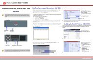
Figure 1-1 shows the front panel of the <strong>RMX</strong> <strong>2000</strong>. The front panel<br />
provides access to the <strong>RMX</strong> <strong>2000</strong> main CNTL modules, MPM/MPM+<br />
modules, Power Supply drawer, Status LEDs, and Fans.<br />
ERR RDY ACT HS<br />
ERR RDY ACT<br />
MPM/MPM+ Cards & LEDs Fan Drawer<br />
<strong>RMX</strong> <strong>2000</strong><br />
Figure 1-1 <strong>RMX</strong> <strong>2000</strong> Front Panel<br />
HS<br />
FAN<br />
STATUS<br />
PWR<br />
STATUS<br />
PWR ERR RDYACT HD HS<br />
FANS<br />
CNTL<br />
Power supply Drawer USB ports - not for Control Unit<br />
customer use & LEDs<br />
MPM+80<br />
MPM+80<br />
CNTL<br />
Optional CPU &<br />
LEDs<br />
Fan &<br />
Power<br />
Status<br />
LEDs<br />
1-7
Chapter 1- <strong>Hardware</strong> Description<br />
1-8<br />
Table 1-3 <strong>Polycom</strong> <strong>RMX</strong> <strong>2000</strong> Component Description<br />
Component Description<br />
CNTL (CPU)<br />
Module<br />
Power Supply<br />
Drawer<br />
The CNTL module controls and manages the <strong>RMX</strong> <strong>2000</strong>.<br />
The CNTL module has an ComExpress Pentium-M<br />
1.4GHz processor, a 40GB hard disk drive, 1GB Compact<br />
Flash and 1GB of DDR RAM.<br />
The Operating System is Linux.<br />
The Power Supply drawer is located below the MPM/<br />
MPM+ Cards and is connected to the backplane by<br />
means of a power connector. It operates at 100-240 volts<br />
AC 50/60 Hz, and provides +48VDC 700W output with<br />
built-in load sharing capabilities.<br />
Fan Drawer Three fans are mounted sideways in a drawer. Airflow is<br />
from right to left, and out the side of the MCU. The drawer<br />
is connected to the Back-plane by a connector.<br />
Multi Processor<br />
Module (MPM)<br />
Card<br />
Multi Processor<br />
Module+ (MPM+)<br />
Card<br />
The MPM cards perform the various RTP, audio and video<br />
processing functions on the <strong>RMX</strong> <strong>2000</strong>. MPM cards are<br />
based on the ATCA standard, with a card manager (CM)<br />
and up to 26 720MHz TI DSP’s.<br />
Two types are available:<br />
• MPM - F - 26 DSP’s<br />
• MPM - H - 13 DSP’s<br />
The MPM+ cards, perform the various RTP, audio and<br />
video processing functions on the <strong>RMX</strong> <strong>2000</strong> unit. TI<br />
C6455 processors are at the core of each MPM+ card<br />
which are available in the following assemblies:<br />
MPM+20 (20 CIF resources)<br />
• MPM+40 (40 CIF resources)<br />
• MPM+80 (80 CIF resources)<br />
Notes:<br />
• The MPM+ card(s) can only work with software<br />
version 4.0. Ensure that software appropriate to the<br />
MCU hardware configuration is installed in the MCU.<br />
• The MPM+ card can work only with a new<br />
environmentally friendly D-type chassis and is<br />
disabled when inserted in a C-type chassis.
<strong>Polycom</strong> <strong>RMX</strong> <strong>2000</strong> <strong>Hardware</strong> <strong>Guide</strong><br />
<strong>RMX</strong> <strong>2000</strong> Rear Panel<br />
RTM IP<br />
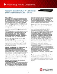
The <strong>RMX</strong> <strong>2000</strong> rear panel contains the RTM IP card and optionally, the<br />
RTM ISDN card. The RTM IP card must be located on the bottom slot in<br />
the rear of the <strong>RMX</strong> <strong>2000</strong>. In addition, the rear panel houses the main<br />
power switch, AC inlet, a circuit breaker, and additional communications<br />
ports.<br />
The RTM IP card provides system management based on the ATCA<br />
standard and connects to the backplane. It controls and monitors the<br />
system fans and regulates power supply. This card contains an Ethernet<br />
Switch that manages the network of the system, routes data between the<br />
cards and components of the system and provides connectivity to external<br />
IP networks.`<br />
The RTM IP card connections include:<br />
• 3 LAN ports<br />
• 10/100Mb ShMG port (Future Use)<br />
• 1 Serial port (Future Use)<br />
• 1 USB port<br />
LAN1, LAN3 and the 10/100Mb ShMG ports shall not be used and the plastic<br />
caps covering those ports should not be removed.<br />
LAN 1-3 Ports<br />
& LEDs<br />
10/100Mb ShMG<br />
LAN & LEDs<br />
Internal LAN<br />
connections<br />
LAN1, LAN 3, ShMG and the Serial ports are only<br />
for debugging and not for customer use<br />
Figure 1-2 <strong>RMX</strong> <strong>2000</strong> RTM IP Rear Panel Layout<br />
Serial<br />
Port<br />
USB<br />
Port<br />
Standby button &<br />
LED<br />
1-9
Chapter 1- <strong>Hardware</strong> Description<br />
1-10<br />
The following items appear on the <strong>RMX</strong> <strong>2000</strong> rear panel:<br />
Table 1-4 <strong>RMX</strong> <strong>2000</strong> Rear Panel - RTM IP Component Description<br />
Item Description<br />
LAN 1 NA - Disconnected.<br />
Note: LAN 1 is covered with a plastic cap that should not<br />
be removed.<br />
LAN 2 Used for the Network connection.<br />
LAN 3 For Remote Access only using the Alternate Management<br />
Network. For more information, see the <strong>RMX</strong> <strong>2000</strong><br />
Administrator’s <strong>Guide</strong>, Appendix F: "Alternate<br />
Management Network” on page H-1.<br />
Note: When not in use, LAN 3 is covered with a plastic<br />
cap that should not be removed.<br />
10/100 ShMG NA - For debugging purposes only.<br />
Note: 10/100 ShMG is covered with a plastic cap that<br />
should not be removed.<br />
Serial NA - For debugging purposes only.<br />
USB USB key connection. For more information, see the <strong>RMX</strong><br />
<strong>2000</strong> Getting Started <strong>Guide</strong>, "First Time Installation and<br />
Configuration” on page 2-1.<br />
Standby button Toggle between CPU activation and standby.
<strong>Polycom</strong> <strong>RMX</strong> <strong>2000</strong> <strong>Hardware</strong> <strong>Guide</strong><br />
RTM ISDN<br />
The RTM ISDN card connects directly to an MPM/MPM+. The RTM<br />
ISDN card routes data between the MPM/MPM+ cards and components<br />
of the system, converts ISDN T1/E1 media to IP packets and provides<br />
connectivity to external ISDN networks.<br />
The RTM ISDN card is installed on the rear panel of the <strong>RMX</strong> interfaces<br />
between the <strong>RMX</strong> unit and the ISDN/PSTN switch. Up to two RTM ISDN<br />
cards can be installed in one <strong>RMX</strong> <strong>2000</strong>.<br />
With the <strong>RMX</strong> <strong>2000</strong>, you can either have a dedicated E1 or T1 Type Network<br />
Service. It is not possible to have a mixed E1 and T1 ISDN Network Service.<br />
An RTM ISDN card must connect directly to an MPM/MPM+ card:<br />
• In an <strong>RMX</strong> with a single MPM/MPM+ card – the RTM ISDN card<br />
must be installed in the rear panel slot on the same level as the MPM/<br />
MPM+ card<br />
In an <strong>RMX</strong> with two MPM/MPM+ cards – the RTM ISDN card can be<br />
installed in either of the two rear panel card slots. Up to a total of 14<br />
E1 or 18 T1 PRI cables can be installed with two MPM/MPM+ and<br />
RTM ISDN cards<br />
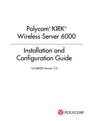
Each RTM ISDN card includes the following connections:<br />
• 7 E1 or 9 T1 PRI lines that can be plugged into any of the 12<br />
connections as shown in Figure 1-3<br />
• 1 LAN port<br />
LAN & LEDs E1/T1 connections<br />
H/S LED<br />
Figure 1-3 <strong>RMX</strong> <strong>2000</strong> RTM ISDN Rear Panel Layout<br />
The RTM ISDN card supports 200 audio participants, regardless of whether the<br />
spans are E1 or T1.<br />
1-11
Chapter 1- <strong>Hardware</strong> Description<br />
1-12<br />
ISDN/PSTN Clock Source<br />
Each RTM ISDN card has its own primary and secondary clock source.<br />
The first span to synchronize becomes the primary clock source and the<br />
second span to synchronize becomes the secondary clock source. This<br />
clock is used to synchronize ISDN spans only (it is not the system clock).<br />
A single clock source triggers an alarm that can be turned off by setting<br />
the appropriate flag in the system configuration.<br />
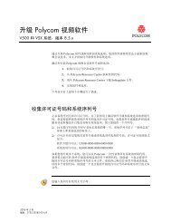
Cables Connected to the RTM IP & ISDN Cards<br />
All external connectors are located on the rear panel.<br />
LAN 2 Connection<br />
E1/T1 Connection<br />
Figure 1-4 <strong>RMX</strong> <strong>2000</strong> Rear Panel View with Cables<br />
Off/On<br />
switch<br />
Power<br />
Cable<br />
Do not remove the protective caps from LAN1, LAN3 and ShMG ports.
<strong>Polycom</strong> <strong>RMX</strong> <strong>2000</strong> <strong>Hardware</strong> <strong>Guide</strong><br />
<strong>RMX</strong> <strong>2000</strong> LEDs<br />
The <strong>RMX</strong> includes LEDs located on the front panel and rear panel. In the<br />
front panel, the LEDs reflect the state of the components. The LEDs on the<br />
rear panel indicate the state of the external connections and the status of<br />
the RTM IP card.<br />
<strong>RMX</strong> <strong>2000</strong> Front Panel LEDs<br />
The following items appear on the <strong>RMX</strong> <strong>2000</strong> front panel:<br />
Table 1-5 <strong>RMX</strong> <strong>2000</strong> Front Panel LED’s<br />
Component LED ID LED Color Description<br />
Fan Status Green OK.<br />
Power Status Green OK.<br />
Red Warning - Fan or power failure.<br />
Red Error - Problem with power supply.<br />
1-13
Chapter 1- <strong>Hardware</strong> Description<br />
1-14<br />
Table 1-5 <strong>RMX</strong> <strong>2000</strong> Front Panel LED’s (Continued)<br />
Component LED ID LED Color Description<br />
MPM/MPM+<br />
Card<br />
ERR Red ON - Major error on card.<br />
Flashes - During card startup.<br />
RDY Green ON - The card has completed<br />
startup successfully.<br />
Flashes - During card startup.<br />
ACT Amber ON - At least one participant is<br />
connected to a conference.<br />
Flashes - During card startup.<br />
HS Blue Flashes - Shut down process<br />
initiated by lightly pulling the CPU<br />
ejector levers. This LED flashes in<br />
synchronization with the CNTL’s<br />
card’s HS LED.<br />
ON - Card is in a power down<br />
mode.<br />
Card removal Initiated - The card<br />
can be removed safely once the<br />
CPU ejector levers are fully open.<br />
Card Insertion Initiated - If during<br />
the startup phase the blue HS LED<br />
remains lit, please ensure that the<br />
card is properly seated in the<br />
chassis. If this problem persists,<br />
contact your next level of support.
<strong>Polycom</strong> <strong>RMX</strong> <strong>2000</strong> <strong>Hardware</strong> <strong>Guide</strong><br />
Table 1-5 <strong>RMX</strong> <strong>2000</strong> Front Panel LED’s (Continued)<br />
Component LED ID LED Color Description<br />
CNTL Unit ERR Red ON - Major system error. In case of<br />
an active alarm this light is ON, and<br />
the RDY green is OFF.<br />
OFF - Normal.<br />
Flashes - During system startup.<br />
RDY Green ON - CPU card has successfully<br />
completed startup. This light turns<br />
green after completing the entire<br />
system configuration.<br />
OFF - Turns OFF when the ERR<br />
red LED is activated.<br />
Flashes - During system startup.<br />
ACT Amber ON - At least one endpoint is<br />
connected to the system.<br />
Flashes - During system startup.<br />
HD Red OFF - Normal.<br />
Flashes - Hard disk is active.<br />
HS Blue Flashes - Indicates when the<br />
power down process is initiated on<br />
an MPM/MPM+ card. This LED<br />
flashes in synchronization with the<br />
MPM/MPM+’s cards HS LED.<br />
OFF - Normal<br />
ON - CPU may be removed.<br />
1-15
Chapter 1- <strong>Hardware</strong> Description<br />
<strong>RMX</strong> <strong>2000</strong> Rear Panel LEDs<br />
1-16<br />
RTM IP<br />
The following LEDs appear on the RTM IP card:<br />
Table 1-6 <strong>RMX</strong> <strong>2000</strong> RTM IP LEDs<br />
Component<br />
LED<br />
Name<br />
LED Color Description<br />
LAN LEDs (1-3) LNK Green ON with an active network<br />
connection, flickers with Packet<br />
activity.<br />
10/100 ShMG<br />
LEDs<br />
SLOT (1-4)<br />
LEDs<br />
1 Gb Amber ON with a 1Gb online<br />
connection, flickers with Packet<br />
activity.<br />
LNK Green ON with an active network<br />
connection, flickers with Packet<br />
activity.<br />
100 Amber ON when the active network is<br />
10/100Mb, flickers with Packet<br />
activity.<br />
LNK (1-4) Green ON with an active network<br />
connection, flickers with Packet<br />
activity.<br />
1Gb (1-4) Amber ON with a 1Gb online<br />
connection, flickers with Packet<br />
activity.
<strong>Polycom</strong> <strong>RMX</strong> <strong>2000</strong> <strong>Hardware</strong> <strong>Guide</strong><br />
Table 1-6 <strong>RMX</strong> <strong>2000</strong> RTM IP LEDs (Continued)<br />
Component<br />
LED<br />
Name<br />
LED Color Description<br />
ShMG LEDs ERR Red ON - Major error on RTM card.<br />
Flashes - During system<br />
startup.<br />
ACT Red ON - Packet flow to and from<br />
the MCU chassis.<br />
Flashes - During system<br />
startup.<br />
RDY Green ON - RTM IP card has<br />
successfully completed startup.<br />
Flashes - During system<br />
startup.<br />
HS Blue OFF - Normal.<br />
Flashes - During power down<br />
process.<br />
ON - RTM IP card may be<br />
removed.<br />
Standby LED Blue ON - CPU & System are in a<br />
standby (OFF) mode.<br />
1-17
Chapter 1- <strong>Hardware</strong> Description<br />
1-18<br />
RTM ISDN<br />
The following LEDs appear on the RTM ISDN:<br />
Table 1-7 <strong>RMX</strong> <strong>2000</strong> RTM ISDN LEDs<br />
Function Name<br />
LED<br />
Name<br />
LED Color Description<br />
LAN LED (1) LNK Green ON with an active network<br />
connection, flickers with Packet<br />
activity.<br />
1 Gb Amber ON when 1Gb connection is<br />
online, flickers with Packet<br />
activity.<br />
ShMC LEDs H/S Blue OFF - Normal.<br />
Flashes - This LED is activated<br />
when the MPM/MPM+ card Hot<br />
Swap functionality initiates a<br />
power off routine on the MPM/<br />
MPM+ and RTM ISDN cards.<br />
ON - Power on the RTM ISDN<br />
card has been switched OFF.<br />
This LED is activated by the<br />
MPM/MPM+ card when the<br />
MPM/MPM+’s card Hot Swap<br />
functionality powers off the<br />
MPM/MPM+ and RTM ISDN<br />
cards.
<strong>Polycom</strong> <strong>RMX</strong> <strong>2000</strong> <strong>Hardware</strong> <strong>Guide</strong><br />
MPM and MPM+ Configuration Modes<br />
The <strong>RMX</strong> unit can work with either MPM or MPM+ (but not with both<br />
simultaneously) media cards. The card Type installed in the system<br />
determines the Card Configuration Mode. When MPM card is installed in<br />
the MCU, it operates in MPM Mode. When MPM+ cards are installed, the<br />
<strong>RMX</strong> operates in MPM+ Mode giving the administrator enhanced control<br />
and monitoring of resource allocation and usage within the system.<br />
MPM+ cards are supported only with d-type chassis and software version<br />
4.0.<br />
Each MPM+ card doubles the MPM capacities. Table 2 summarizes the<br />
resource capacities of the various video resource types in an <strong>RMX</strong><br />
containing two MPM and MPM+ cards.<br />
Table 2 MPM+ and MPM Resource Capacity<br />
Port Type<br />
Maximum Possible<br />
MPM MPM+<br />
Voice 400 800<br />
CIF 80 160<br />
SD30 20 60<br />
HD720p 20 40<br />
HD1080p – 20<br />
• <strong>RMX</strong>s with 500MB of memory can support a maximum of 400 simultaneous<br />
voice calls and 120 CIF video calls, regardless of how system resources are<br />
allocated. This limitation applies to <strong>RMX</strong>s configured with either MPM or<br />
MPM+ cards.<br />
<strong>RMX</strong>s with 1000MB of memory are not subject to this limitation.<br />
• <strong>RMX</strong> memory size is listed in the Administration > System Information<br />
properties box.<br />
1-19
Chapter 1- <strong>Hardware</strong> Description<br />
MPM+ Resource Capacities<br />
1-20<br />
The MPM+ card offers increased resource capacities and capabilities.<br />
Three MPM+ card assemblies are available: MPM+ 80, MPM+ 40 and<br />
MPM+ 20 offering various resource capacities for CP conferences.<br />
In CP conferences:<br />
• Frame rate has been increased – with HD720p now up to 60fps.<br />
• Video resolution has been increased up to HD1080p.<br />
• Bandwidth is up to 4 Mbps.<br />
Table 3 summarizes the increased video capacities of the various MPM+<br />
card assemblies.<br />
Table 3 MPM+ Card Assemblies and Capacities for CP Conferences<br />
Card<br />
Type<br />
Voice CIF<br />
SD<br />
@30fps<br />
Resources<br />
HD720p<br />
@30fps<br />
HD720p<br />
@60fps<br />
HD1080p<br />
@30fps<br />
MPM+ 80 400 80 30 20 10 10<br />
MPM+ 40 200 40 15 10 5 5<br />
MPM+ 20 100 20 8 5 2 2<br />
In HD Video Switching conferences:<br />
The recommended number of connections at HD1080p resolution in an<br />
<strong>RMX</strong> with two MPM+ cards is:<br />
• 160 participants at line rates of up to 2Mbps<br />
• 80 participants at line rates of up to 4Mbps<br />
• 40 participants at line rates of up to 6Mbps<br />
Bandwidth<br />
Up to<br />
4Mbps
<strong>Polycom</strong> <strong>RMX</strong> <strong>2000</strong> <strong>Hardware</strong> <strong>Guide</strong><br />
MPM and MPM+ Modes<br />
• MPM+ and MPM cards installed in the system cannot be used<br />
simultaneously. Therefore, the <strong>RMX</strong> can operate in either MPM or<br />
MPM+ Mode.<br />
Operating Mode Selection During Startup / Restart<br />
• When started with Version 4.0 installed, the <strong>RMX</strong> enters MPM+ Mode<br />
by default, even if no media cards are installed.<br />
• When upgrading a system from Version 3 (or lower) with Version 4.0<br />
software downloaded from the <strong>Polycom</strong> Resource Center, the <strong>RMX</strong><br />
enters MPM Mode by default.<br />
• The <strong>RMX</strong> only switches between MPM and MPM+ Card Configuration<br />
Modes if MPM/MPM+ cards are removed or swapped while it is running.<br />
• The Card Configuration Mode switch occurs during the next restart.<br />
• Installing or swapping MPM/MPM+ cards while the system is off will not<br />
cause a mode switch when the system is restarted – it will restart in the Card<br />
Configuration Mode that was active previous to powering down.<br />
Table 4 summarizes the Operating Mode After Next Restart resulting from of<br />
adding or swapping MPM/MPM+ cards in a running system.<br />
Table 4 Card Configuration Mode After Next Restart<br />
Current<br />
Operating<br />
Mode<br />
MPM+<br />
Media<br />
Cards<br />
Installed<br />
MPM<br />
or<br />
MPM x 2<br />
MPM<br />
and<br />
MPM+<br />
MPM+<br />
or<br />
MPM+ x 2<br />
Card(s)<br />
Supported<br />
Card(s)<br />
Disabled<br />
Operating<br />
Mode After<br />
Next Restart<br />
None All MPM<br />
MPM+ Only<br />
MPM<br />
Only<br />
MPM+<br />
All None MPM+<br />
1-21
Chapter 1- <strong>Hardware</strong> Description<br />
1-22<br />
Table 4 Card Configuration Mode After Next Restart<br />
Current<br />
Operating<br />
Mode<br />
MPM<br />
Media<br />
Cards<br />
Installed<br />
MPM<br />
or<br />
MPM x 2<br />
MPM<br />
and<br />
MPM+<br />
MPM+<br />
or<br />
MPM+ x 2<br />
Card(s)<br />
Supported<br />
Example 1:<br />
Current status<br />
An <strong>RMX</strong> has two MPM cards installed.<br />
The Card Configuration Mode is MPM.<br />
Both MPM cards are enabled.<br />
Action<br />
1. Remove one MPM card.<br />
2. Insert one MPM+ card.<br />
Result<br />
The Card Configuration Mode remains MPM.<br />
The remaining MPM card remains enabled.<br />
The inserted MPM+ card is disabled.<br />
After Reset<br />
The Card Configuration Mode is MPM+.<br />
The inserted MPM+ card is enabled.<br />
The remaining MPM card is disabled.<br />
All None MPM<br />
MPM<br />
Only<br />
Card(s)<br />
Disabled<br />
Operating<br />
Mode After<br />
Next Restart<br />
MPM+ Only MPM+<br />
None All MPM+
<strong>Polycom</strong> <strong>RMX</strong> <strong>2000</strong> <strong>Hardware</strong> <strong>Guide</strong><br />
Example 2:<br />
Current status<br />
An <strong>RMX</strong> has one MPM+ card installed.<br />
The Card Configuration Mode is MPM+.<br />
and the MPM+ card is enabled.<br />
Action<br />
1. Remove the MPM+ card.<br />
2. Insert one MPM card.<br />
Result<br />
The Card Configuration Mode remains MPM+.<br />
The inserted MPM card is disabled.<br />
1-23
Chapter 1- <strong>Hardware</strong> Description<br />
<strong>RMX</strong> Chassis Types<br />
1-24<br />
The <strong>RMX</strong> chassis can be of type A/B/C or D. The environmentally<br />
friendly D-type chassis (indicated by the letter D in the Part Number) is<br />
required for use with MPM+ card(s).<br />
The chassis type can be viewed in the <strong>Hardware</strong> Monitor, by right<br />
clicking Slot 0 and then clicking Properties.<br />
The <strong>RMX</strong> <strong>2000</strong> - General Information dialog box opens.<br />
The <strong>RMX</strong> Part Number contains the letter A/B/C/D that represents the<br />
chassis type, as shown in the capture above.<br />
For more details, see the <strong>RMX</strong> Administrator’s <strong>Guide</strong>, Chapter 15,<br />
“<strong>Hardware</strong> Monitoring” .
<strong>Polycom</strong> <strong>RMX</strong> <strong>2000</strong> <strong>Hardware</strong> <strong>Guide</strong><br />
Component Replacement<br />
The <strong>RMX</strong> <strong>2000</strong> is designed with ease of maintenance in mind. Most<br />
components are swappable and are accessible directly via the front panel<br />
or the rear panel.<br />
Only MPM/MPM+ cards are Hot Swappable. The RTM IP and RTM ISDN card<br />
are not Hot Swappable. System shutdown is required when replacing the RTM<br />
ISDN or RTM IP card.<br />
The following components can be replaced when they are faulty:<br />
• CNTL Module, see "Replacing the CNTL Module” on page 1-27.<br />
• Power Supply Module, see "Replacing the Power Supply Module” on<br />
page 1-29.<br />
• Fan drawer, see "Replacing the Fan Drawer” on page 1-30.<br />
• MPM/MPM+ card. This card is hot-swap enabled. See "Replacing a<br />
Faulty MPM/MPM+ Card” on page 1-31.<br />
• RTM ISDN card, see "Replacing a RTM ISDN Card” on page 1-33<br />
• RTM IP card, see "Replacing the RTM IP Card” on page 1-34.<br />
Warning!<br />
• All maintenance tasks are to be performed by qualified, authorized<br />
personnel.<br />
• Use only replacement parts supplied by your dealer.<br />
• Follow all procedures. Do not skip any steps.<br />
Before replacing parts:<br />
• To ensure a part needs replacing, complete the troubleshooting<br />
procedures.<br />
• Identify exactly which part needs replacing.<br />
• Make sure you have the correct replacement part on hand.<br />
• Make sure you are using proper ESD equipment, to prevent damage<br />
to the system.<br />
Note!<br />
On all cards, if during the startup phase the blue HS LED remains lit, please<br />
make sure that the card is properly seated in it’s slot. If this problem persists,<br />
contact your next level of support.<br />
1-25
Chapter 1- <strong>Hardware</strong> Description<br />
Types of Ejector Levers on <strong>RMX</strong> Components<br />
1-26<br />
On the <strong>RMX</strong>, 2 types of ejector levers can be attached to the cards:<br />
• An all metal (silver) lever<br />
• A modified PMC compatible ejector lever covered by plastic caps<br />
with a lock catch<br />
Using the All Metal Ejector Lever<br />
This ejector lever can be moved to 3 positions:<br />
• Closed - The ejector levers are fully retracted and pushed up against<br />
the card’s panel<br />
• Partially Open - For card powering down mode. Partially open the<br />
ejector lever(s) until the blue HS LEDs on the card and the Control<br />
Unit start flashing. When the HS LED is constantly lit the card is in a<br />
powered down mode and you can remove the card.<br />
Warning!<br />
Once the removal sequence is initiated and the HS led flashes, the process<br />
cannot be terminated when activated.<br />
• Fully Open - The card is released from the MCU housing<br />
Using the Modified PMC Compatible Ejector Lever<br />
This ejector lever can be moved to 3 positions:<br />
• Closed/Locked - Ejector lever(s) are gently pushed up against the<br />
card’s panel and is locked. Ensure that the lock catch is in the<br />
standard closed position (shifted to the right as shown below).<br />
Handle<br />
Closing the Lever - Make sure that the lever is in<br />
an open position and push card close to the<br />
chassis till the lever engages. With your index<br />
finger holding the “handle” and your thumb holding<br />
the catch fully to left, push the card against the<br />
chassis whilst closing the lever. Release Lock<br />
Catch and allow it to “click” into place, ensuring that<br />
the card is properly placed against the chassis.<br />
Unlocking the Lock Catch - With your index<br />
finger holding the “handle” and your thumb shifting<br />
the catch to left, gently pull the handle away from<br />
the chassis until the lever is “fully open”
<strong>Polycom</strong> <strong>RMX</strong> <strong>2000</strong> <strong>Hardware</strong> <strong>Guide</strong><br />
• Partially Open - For card powering down mode. Partially open the<br />
ejector lever(s) until the blue HS LEDs on the card and the Control<br />
Unit start flashing. When the HS LED is constantly lit the card is in a<br />
powered down mode and you can remove the card.<br />
Warning!<br />
Once the removal sequence is initiated the process cannot be terminated and<br />
the HS led flashes when activated.<br />
• Fully Open - In this position the card is released from the MCU<br />
housing and can be removed.<br />
Replacing the CNTL Module<br />
Lever Fully Open - Pull the lever handle(s) to a<br />
fully open position (approx. 70 degrees), as<br />
shown here<br />
The CPU module is the management system of the <strong>RMX</strong> <strong>2000</strong>. Use the<br />
following procedure to replace a CNTL Module:<br />
1 Ensure that power switch on the <strong>RMX</strong> <strong>2000</strong> is turned OFF (O).<br />
2 Unscrew the captive screws on the front panel of the <strong>RMX</strong> <strong>2000</strong> that<br />
secure the CNTL Module.<br />
3 Use the metal ejector levers to pull the CNTL Module out of its slot in<br />
the Backplane.<br />
4 Carefully slide the CNTL Module out through the front panel.<br />
1-27
Chapter 1- <strong>Hardware</strong> Description<br />
1-28<br />
5 On the CNTL Module to be installed, move the ejector lever to the<br />
fully open position.<br />
6 Slide in the replacement CNTL Module.<br />
7 Push the CNTL Module firmly into the Backplane, making sure it is<br />
properly seated in its slot.<br />
8 Ensure that the metal ejector levers are fully retracted into their<br />
housings.<br />
9 Tighten the captive screws on the front panel of the <strong>RMX</strong> <strong>2000</strong> that<br />
secure the Functional CNTL Module.<br />
10 Turn ON the <strong>RMX</strong> <strong>2000</strong>.<br />
For more information on the Card Configuration Modes after reset, see "MPM<br />
and MPM+ Configuration Modes” on page 1-19.
<strong>Polycom</strong> <strong>RMX</strong> <strong>2000</strong> <strong>Hardware</strong> <strong>Guide</strong><br />
Replacing the Power Supply Module<br />
A single supply unit powers the <strong>RMX</strong> <strong>2000</strong>. Use the following procedure<br />
to replace a Power Supply:<br />
Please verify the type of power supply used on your <strong>RMX</strong> <strong>2000</strong>. Do not insert a<br />
different type of power supply than the current type installed on your system.<br />
1 Ensure that the power switch on the <strong>RMX</strong> <strong>2000</strong> is turned OFF (O) and<br />
that the power cords are disconnected from the MCU.<br />
2 Unscrew the captive screws on the front panel of the <strong>RMX</strong> <strong>2000</strong> that<br />
secure the Power Supply unit.<br />
3 Use the finger grip to pull the Power Supply unit out of its slot in the<br />
Backplane.<br />
4 Carefully slide the Power Supply unit out through the front panel.<br />
5 Slide in the replacement Power Supply unit.<br />
6 Push the Power Supply unit firmly into the Backplane, making sure it<br />
is properly seated in its slot.<br />
7 Ensure that the metal ejector levers are fully retracted into their<br />
housings.<br />
8 Tighten the captive screws on the front panel of the <strong>RMX</strong> <strong>2000</strong> that<br />
secure the Power Supply unit.<br />
9 Turn ON the <strong>RMX</strong> <strong>2000</strong>.<br />
For more information on the Card Configuration Modes after reset, see "MPM<br />
and MPM+ Configuration Modes” on page 1-19.<br />
1-29
Chapter 1- <strong>Hardware</strong> Description<br />
Replacing the Fan Drawer<br />
1-30<br />
Three fans are mounted in the Fan drawer, where the airflow is from right<br />
to left. Should one of these fans fail as indicated by a Fan LED, you are<br />
required to replace the Fan drawer.<br />
1 Unscrew the captive screws on the front panel of the <strong>RMX</strong> <strong>2000</strong> that<br />
secure the Fan drawer.<br />
2 Use the metal ejector levers to pull the Fan drawer out of its slot in the<br />
Backplane.<br />
3 Carefully slide the Fan drawer out through the front panel.<br />
Warning!<br />
The Fan drawer can be replaced when the <strong>RMX</strong> unit is ON, however a<br />
replacement drawer must be inserted immediately. The temperature increase is<br />
detected by the system, when critical, a system shutdown is initiated.<br />
4 Slide in the replacement Fan drawer.<br />
5 Push the Fan drawer firmly into the Backplane, making sure it is<br />
properly seated in its slot.<br />
6 Ensure that the metal ejector levers are fully retracted into their<br />
housings.<br />
7 Tighten the captive screws on the front panel of the <strong>RMX</strong> <strong>2000</strong> that<br />
secure the Fan drawer.
<strong>Polycom</strong> <strong>RMX</strong> <strong>2000</strong> <strong>Hardware</strong> <strong>Guide</strong><br />
Replacing a Faulty MPM/MPM+ Card<br />
Removing the MPM/MPM+ Card from the MCU<br />
All MPM/MPM+ cards can be installed or removed while the <strong>RMX</strong> <strong>2000</strong><br />
is powered on and operating.<br />
Prior to removing an MPM/MPM+ card the captive screws must be<br />
unscrewed and the ejector levers must be opened to initiate a “power<br />
down” on the card.<br />
1 If applicable, loosen the captive screws and remove the slot cover.<br />
2 Power down the card by partially opening the ejector levers until the<br />
blue HS LED on the card and the Control Unit start to flash.<br />
Warning!<br />
Once the removal sequence is initiated the process cannot be terminated and<br />
the HS LED flashes.<br />
3 The power off sequence for the interconnected MPM/MPM+ and<br />
RTM ISDN cards are initiated as follows:<br />
— All participant connections on the card are disconnected.<br />
— A fault is generated on the system.<br />
— For each disconnected participant, a participant disconnection<br />
event is written to the CDR with the disconnection cause<br />
Disconnected by Operator.<br />
— New participant connections are blocked when the card is<br />
removed.<br />
— If an RTM ISDN card is connected to the MPM/MPM+ card it is<br />
also powered off and all ISDN and PSTN participants are<br />
disconnected.<br />
— When an RTM ISDN card is removed, its resources are deducted<br />
from the Resource Report.<br />
— A Log File entry is written indicating MPM/MPM+ card removal.<br />
— Port usage is re-calculated and the Port Gauges and Video/Voice<br />
Port Configuration dialog box are updated.<br />
4 When the blue HS LEDs on the MPM+, RTM ISDN and Control Unit<br />
stop flashing and remain lit, unscrew the captive screws and move<br />
the ejector levers to their fully open position and remove the MPM/<br />
MPM+ card.<br />
1-31
Chapter 1- <strong>Hardware</strong> Description<br />
1-32<br />
5 Carefully slide the MPM/MPM+ card out through the front panel.<br />
Installing the Replacement MPM/MPM+ Card<br />
1 On the card to be installed, move the ejector levers to their fully open<br />
position.<br />
2 Slide in the replacement MPM/MPM+ card.<br />
3 Push the MPM/MPM+ card firmly into the Backplane, making sure it<br />
is properly seated in its slot.<br />
4 Ensure that the metal ejector levers are fully retracted into their<br />
housings.<br />
5 Tighten the captive screws on the front panel of the <strong>RMX</strong> that secure<br />
the MPM/MPM+ card to the chassis.<br />
Installing a New MPM/MPM+ Card in a Powered On <strong>RMX</strong><br />
<strong>2000</strong><br />
1 If applicable, loosen the captive screws and remove the slot cover.<br />
2 On the card to be installed, move the ejector levers to their full open<br />
position.<br />
3 Insert the card into the slot until the ejector levers touch the front<br />
edge of the card cage.<br />
4 Push the ejector levers to their closed position and tighten the captive<br />
screws on each side of the card, securing the MPM/MPM+ card to<br />
the <strong>RMX</strong>.
<strong>Polycom</strong> <strong>RMX</strong> <strong>2000</strong> <strong>Hardware</strong> <strong>Guide</strong><br />
Replacing a RTM ISDN Card<br />
The blue HS LEDs on the MPM/MPM+ card and the Control Unit<br />
start flashing and the power on cycle for the card is initiated:<br />
— The card’s resources are added to the system resources list<br />
— The number of available ports on the <strong>RMX</strong> is increased to the<br />
current CFS license level<br />
— Port usage is re-calculated and the Port Gauges and Video/Voice<br />
Port Configuration are updated<br />
When the power on cycle of the MPM/MPM+ card is completed, the<br />
blue HS LEDs will turn OFF. The green RDY LED on the MPM/<br />
MPM+ card switches on and remains lit.<br />
The RTM ISDN card can only be used with software version 3.0 of higher.<br />
1 Ensure that the power switch on the <strong>RMX</strong> <strong>2000</strong> is turned OFF (O).<br />
2 Loosen the captive screws that fasten the card to the MCU.<br />
3 Remove the RTM ISDN card. Use the metal ejector levers to pull the<br />
RTM ISDN card out of its slot in the backplane.<br />
4 Carefully slide the RTM ISDN card out through the front panel.<br />
5 On the card to be installed, move the ejector levers to their fully open<br />
position.<br />
Ejector Lever Captive Screw<br />
1-33
Chapter 1- <strong>Hardware</strong> Description<br />
1-34<br />
6 Slide in the replacement RTM ISDN card.<br />
7 Insert the card into the slot until the ejector levers touch the front<br />
edge of the card cage.<br />
8 Push the ejector levers to their fully closed position.<br />
9 Tighten the captive screws on each side of the rear panel of the card,<br />
securing the RTM ISDN card to <strong>RMX</strong>.<br />
10 Turn ON the <strong>RMX</strong> <strong>2000</strong>.<br />
11 Connect the RJ-45 terminated PRI cables into any of the slots labeled<br />
PRI1 - PRI12:<br />
PRI Cables<br />
LAN Power<br />
7 E1 or 9 T1 cables can be connected to each RTM ISDN card, up to a<br />
total of 14 E1 or 18 T1 PRI cables when two RTM ISDN cards are<br />
installed.
<strong>Polycom</strong> <strong>RMX</strong> <strong>2000</strong> <strong>Hardware</strong> <strong>Guide</strong><br />
Replacing the RTM IP Card<br />
The RTM IP card on the rear of the <strong>RMX</strong> <strong>2000</strong> provides connectivity to all<br />
the MCU modules. Use the following procedure to replace the RTM IP<br />
card:<br />
1 Ensure that the power switch on the <strong>RMX</strong> <strong>2000</strong> is turned OFF (O).<br />
2 Unscrew the captive screws on the rear panel of the <strong>RMX</strong> <strong>2000</strong> that<br />
secure the RTM IP card.<br />
3 Use the metal ejector levers to pull the RTM IP card out of its slot in<br />
the backplane.<br />
4 Carefully slide the RTM IP card out through the rear panel.<br />
5 On the card to be installed, move the ejector levers to their fully open<br />
position.<br />
6 Slide in the replacement RTM IP card.<br />
7 Push the RTM IP card firmly into the backplane, making sure it is<br />
properly seated in its slots.<br />
8 Ensure that the metal ejector levers are fully retracted into their<br />
housings.<br />
9 Tighten the captive screws on the rear panel of the <strong>RMX</strong> <strong>2000</strong> that<br />
secure the RTM IP card.<br />
10 Turn ON the <strong>RMX</strong> <strong>2000</strong>.<br />
For more information on the Card Configuration Modes after reset, see "MPM<br />
and MPM+ Configuration Modes” on page 1-19.<br />
1-35