MANUBAL V60 instructions - MX
MANUBAL V60 instructions - MX
MANUBAL V60 instructions - MX

Create successful ePaper yourself
Turn your PDF publications into a flip-book with our unique Google optimized e-Paper software.
User Manual<br />
<strong>MANUBAL</strong><br />
<strong>V60</strong><br />
Read carefully before operating<br />
the Manubal<br />
UK 365509 AA - 0511<br />
Original <strong>instructions</strong>
Dear user,<br />
We thank you for placing your trust in our product and hope you will find your <strong>MX</strong> <strong>MANUBAL</strong> satisfactory in every<br />
way.<br />
Taking a few minutes to read this manual will enable you to use the capabilities of your <strong>MX</strong> <strong>MANUBAL</strong> to the full,<br />
prolong its service life and ensure safe operation.<br />
The <strong>MANUBAL</strong> user manual before you is an important document, please retain it in order to be able to refer to it<br />
if required. Make it available to any other users and hand it over it to any new owner in the event of your <strong>MX</strong><br />
<strong>MANUBAL</strong> being sold on.<br />
The illustrations and technical data shown in this document might not match your <strong>MX</strong> <strong>MANUBAL</strong> bale grab<br />
exactly, operating conditions will nevertheless remain the same.
TABLE OF CONTENTS<br />
1. SAFETY RULES 4<br />
2. SAFETY STICKERS 5<br />
3. IDENTIFICATION PLATE 5<br />
4. DESCRIPTION 6<br />
5. HITCHING/UNHITCHING THE <strong>MANUBAL</strong> BALE GRAB 7<br />
6. GRAB OPENING / CLOSING ADJUSTMENT 8<br />
7. WRAPPED BALE GRAB KIT 10<br />
8. PRINCIPLE OF USE 11<br />
9. MAINTENANCE / STORAGE 12<br />
10. TECHNICAL SPECIFICATIONS 13<br />
EC DECLARATION OF CONFORMITY<br />
Page
1. SAFETY RULES<br />
The tractor/loader/<strong>MANUBAL</strong> bale grab combination must only be operated by trained and experienced personnel.<br />
— For your complete safety and that of others, strict compliance with the hitching and unhitching procedure for the<br />
<strong>MANUBAL</strong> bale grab is required (chapter 5 of this manual).<br />
— Only control the <strong>MANUBAL</strong> bale grab from the driver’s seat. Keep operating the controls until movements stop.<br />
— Do not leave the driver’s seat without stopping all control movements.<br />
— All personnel must be kept away from the area in which the loader - <strong>MANUBAL</strong> bale grab combination is moving while it is<br />
in operation.<br />
— Never pass under a raised bale. Never use the <strong>MANUBAL</strong> bale grab to push a bale.<br />
— Carrying or lifting personnel using the <strong>MANUBAL</strong> bale grab is forbidden. Never stand or pass under the load.<br />
— Before any operation, the user must ensure that the <strong>MANUBAL</strong> bale grab is in proper working order and can be used in<br />
complete safety. He must also check and ensure that the tractor-loader-<strong>MANUBAL</strong> bale grab combination is stable by fitting<br />
a counterweight to the back of the tractor. This should ensure that 20% of gross weight remains on the rear axle of the tractor<br />
for optimum safety while travelling and working.<br />
— When travelling on the road it is imperative that the regulations governing use on the public highway be observed (size,<br />
implement markings, etc.) Protruding items such as tine ends must be protected or stowed (grab closed, lower tine kit<br />
retracted).<br />
— Take great care when operating at height in order to avoid catching any items (electric power or telephone lines, guttering,<br />
roof trusses, etc.).<br />
— Whenever the tractor is stopped momentarily or for an extended period, the engine must be shut down and the <strong>MANUBAL</strong><br />
bale grab lowered.<br />
— When not in use, protruding items such as tine ends must be protected or stowed (grab closed).<br />
— Check periodically to ensure that safety pins and bolts are in place. Do not replace them with any other items such as: nails,<br />
wire, etc.<br />
— Any adjustment on the <strong>MANUBAL</strong> bale grab (ram position, etc.) must be carried out after the <strong>MANUBAL</strong> bale grab has been<br />
lowered to the ground and the tractor engine shut down.<br />
— Any work involving fault tracing (diagnostics) and/or disassembly of parts may only be undertaken by a skilled technician<br />
who will start with an assurance that the work will be carried out in complete safety for himself and his surroundings.<br />
• 19, rue de Rennes • BP 83221 • F - 35690 ACIGNÉ<br />
Caution !<br />
— Check hoses for length and routing in all configurations (fully crowded, fully dumped, etc.) before first use.<br />
— The <strong>MANUBAL</strong> bale grab is designed to withstand a maximum operating pressure of 210 bar. Above this pressure, the<br />
<strong>MANUBAL</strong> bale grab will require to be fitted with a pressure limiter.<br />
— Any instance of a <strong>MANUBAL</strong> bale grab being fitted which ignores the recommendations in the <strong>MX</strong> price list in force on the<br />
date of purchase will void <strong>MX</strong> warranty on the entire supply.<br />
— Any modification to any part of the <strong>MX</strong> supply (rams, grab, tines, crank, etc.) or use of a component installed on the<br />
<strong>MANUBAL</strong> bale grab which has not originated from <strong>MX</strong> will void <strong>MX</strong> warranty on the entire <strong>MX</strong> supply.<br />
— Use only genuine <strong>MX</strong> spare parts. Do not modify your <strong>MANUBAL</strong> bale grab yourself or have it modified by anyone else,<br />
without first requesting written authorisation from <strong>MX</strong>. Failure to comply with these rules may render your <strong>MANUBAL</strong> bale<br />
grab hazardous. In the event of damage or injury, <strong>MX</strong> shall not be held responsible in any way.<br />
— Warranty cover will cease immediately in the event of failure to observe the standards and <strong>instructions</strong> for use and<br />
maintenance of the <strong>MANUBAL</strong> bale grab as stipulated in the user manual.<br />
THE INSTALLER SHALL BE FULLY LIABLE FOR ANY FITMENT ON A LOADER OTHER THAN <strong>MX</strong> OR A TELESCOPIC<br />
HANDLER WHICH HAS NOT BEEN RECOMMENDED BY <strong>MX</strong>.<br />
4 Modification reserved
2. SAFETY STICKERS<br />
Ensure the labels are clean and legible; replace them if damaged.<br />
1. Location: <strong>MANUBAL</strong> frame carrier<br />
— Familiarise yourself with the safety rules in the user manual<br />
before using or working on the unit.<br />
3. IDENTIFICATION PLATE<br />
Identification details are to be passed on to your dealer with any request for spare parts or service work. Its location is shown<br />
below.<br />
2. Location: <strong>MANUBAL</strong> frame carrier<br />
— <strong>MANUBAL</strong> identification data plate<br />
19, rue de Rennes F - 35690 ACIGNÉ<br />
Désignation/<br />
Designation<br />
Type / Model / Typ<br />
N˚ de série<br />
Serial number<br />
Seriennummer<br />
Poids à vide<br />
Unloaded weight / Leergewicht<br />
Année / Year<br />
kg<br />
• 19, rue de Rennes • BP 83221 • F - 35690 ACIGNÉ<br />
328462<br />
OK<br />
516154<br />
2<br />
19, rue de Rennes F - 35690 ACIGNÉ<br />
Désignation/<br />
Designation<br />
Type / Model / Typ<br />
N˚ de série<br />
Serial number<br />
Seriennummer<br />
Année / Year<br />
Poids à vide<br />
Unloaded weight / Leergewicht<br />
kg<br />
328462<br />
5 Modification reserved<br />
1<br />
OK<br />
516154
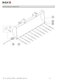
4. DESCRIPTION<br />
1<br />
1. Bracket<br />
2. Grab<br />
3. Tine<br />
4. Ram<br />
3 8<br />
4<br />
5. Synchronising crank<br />
• 19, rue de Rennes • BP 83221 • F - 35690 ACIGNÉ<br />
5<br />
6<br />
7<br />
2<br />
6. Synchronising link<br />
7. Rod-end ram pin<br />
8. Cylinder-end ram pin<br />
9. Telescopic connecting bar<br />
10. Upper connecting bar<br />
6 Modification reserved
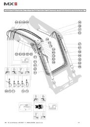
5. HITCHING/UNHITCHING THE <strong>MANUBAL</strong> BALE GRAB<br />
5.1 HITCHING THE <strong>MANUBAL</strong> BALE GRAB<br />
5.1.1 Hook the self-centring V notches into the <strong>MANUBAL</strong> hitch bar (for telescopic handlers, refer to the manufacturer’s user<br />
manual).<br />
5.1.2 Position yourself on the right-hand side and lock manually.<br />
5.1.3 Crowd back to check that the <strong>MANUBAL</strong> is being held correctly.<br />
5.1.4 Operate each moving component to its fullest extent in each direction to check the hydraulic system is free from leaks<br />
and the hoses are routed correctly.<br />
1 2<br />
3<br />
5.2 UNHITCHING THE <strong>MANUBAL</strong> BALE GRAB<br />
5.2.1 Remove the <strong>MANUBAL</strong> unit with the grab open (ram rod<br />
retracted).<br />
5.2.2 Release the hydraulic pressure and unhitch.<br />
• 19, rue de Rennes • BP 83221 • F - 35690 ACIGNÉ<br />
Position for locking the<br />
<strong>MANUBAL</strong> bale grab<br />
7 Modification reserved
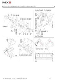
6. GRAB OPENING / CLOSING ADJUSTMENT<br />
The extent of opening and closing of the grab can be adjusted to match the type of bale being handled.<br />
6.1 ROUND BALES<br />
This setting enables 0.90m to 1.80m diameter<br />
bales to be picked up.<br />
6.1.1 Position the <strong>MANUBAL</strong> bale grab upright.<br />
6.1.2 Open the grab halfway. Lower the <strong>MANUBAL</strong> bale grab to<br />
the ground. Stop the engine.<br />
6.1.3 Remove the clip from the rod-end ram pin and remove the<br />
pin.<br />
Note: the screw on the pin flat acts to prevent rotation and<br />
need not be removed.<br />
6.1.4 Position the ram opposite the hole for the round bale<br />
setting. See table below.<br />
6.1.5 Insert the pin as well as the synchronising link in the<br />
appropriate hole.<br />
Note: check the spacers for correct positioning.<br />
6.1.6 Refit the clip.<br />
6.1.7 Repeat operations 6.1.3 to 6.1.6 for the cylinder-end ram<br />
pin.<br />
• 19, rue de Rennes • BP 83221 • F - 35690 ACIGNÉ<br />
364187_10<br />
Synchronising links - Viewed from below<br />
8 Modification reserved
6.2 RECTANGULAR BALE<br />
With the grab open, the tines do not extend beyond<br />
the vertical mast. Rectangular bale pick-up is more<br />
effective.<br />
6.2.1 Position the <strong>MANUBAL</strong> bale grab upright.<br />
6.2.2 Open the grab halfway. Lower the <strong>MANUBAL</strong> bale grab to<br />
the ground. Stop the engine.<br />
6.2.3 Remove the clip from the rod-end ram pin and remove the<br />
pin.<br />
Note: the screw on the pin flat acts to prevent rotation and<br />
need not be removed.<br />
6.2.4 Position the ram opposite the hole for the rectangular bale<br />
setting. See table below.<br />
6.2.5 Insert the pin as well as the synchronising link in the<br />
appropriate hole.<br />
Note: check the spacers for correct positioning.<br />
6.2.6 Refit the clip.<br />
6.2.7 Repeat operations 6.2.3 to 6.2.6 for the cylinder-end ram<br />
pin.<br />
• 19, rue de Rennes • BP 83221 • F - 35690 ACIGNÉ<br />
364187_11<br />
Synchronising links - Viewed from below<br />
9 Modification reserved
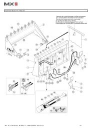
7. WRAPPED BALE GRAB KIT*<br />
This kit converts your <strong>MANUBAL</strong> unit into a round wrapped bale<br />
grab. The conversion is very simple and is accomplished in just a<br />
few seconds.<br />
Wrapped bale grab opening / closing adjustment<br />
The adjustment is carried out using the holes provided for round<br />
wrapped bales.<br />
7.1 Position the <strong>MANUBAL</strong> bale grab upright.<br />
7.2 Open the grab halfway. Lower the <strong>MANUBAL</strong> bale grab to<br />
the ground. Stop the engine.<br />
7.3 Remove the clip from the rod-end ram pin and remove the<br />
pin.<br />
Note: the screw on the pin flat acts to prevent rotation and<br />
need not be removed.<br />
7.4 Position the ram opposite the hole for the wrapped bale<br />
setting. See drawing 1 .<br />
7.5 Insert the pin as well as the synchronising link in the<br />
appropriate hole.<br />
Note: check the spacers for correct positioning.<br />
7.6 Refit the clip.<br />
7.7 Repeat operations 7.3 to 7.6 for the cylinder-end ram pin.<br />
CAUTION: the synchronising links should be removed from the<br />
<strong>MANUBAL</strong> bale grab when it is used for wrapped bales, which<br />
allows the 2 grab arms to float. This enhances effectiveness and<br />
safety when stacking bales contiguously.<br />
7.8 Position the first side of the wrapped bale grab kit<br />
(U-section) against the grab tine carrier.<br />
7.9 Position the other side of the wrapped bale grab kit<br />
(O-section) opposite the hole provided for this purpose<br />
in the <strong>MANUBAL</strong> grab.<br />
7.10 Insert the pin and the clip supplied in the kit.<br />
7.11 Repeat operations 7.8 to 7.10 for the other kit.<br />
Note: the kit is not handed as regards assembly. It is<br />
identical for the left and right-hand sides.<br />
* Option<br />
• 19, rue de Rennes • BP 83221 • F - 35690 ACIGNÉ<br />
1<br />
U<br />
U<br />
O<br />
O<br />
10 Modification reserved
8. PRINCIPLE OF USE<br />
8.1 Holding the bale on its cylindrical face<br />
8.2 Holding the bale on its flat face<br />
• 19, rue de Rennes • BP 83221 • F - 35690 ACIGNÉ<br />
11 Modification reserved
9. MAINTENANCE / STORAGE<br />
9.1 Maintenance<br />
— Lubricate pivot points regularly. See lubrication points below.<br />
— Ensure hydraulic connections are cleaned each time before they are connected.<br />
— See to it that straw or hay residues do not jam up the pivot points.<br />
— Check the <strong>MANUBAL</strong> bale grab to ensure that it is in proper working order throughout and that screws, clips and pins are<br />
in place before any use.<br />
— Check the condition of the wear bushes and replace them before they are fully worn.<br />
Lubrication points:<br />
9.2 Storage<br />
— Unhitch the <strong>MANUBAL</strong> bale grab with the grab opened (ram rod retracted).<br />
— Lubricate pivot points.<br />
— Coat the tines with oil.<br />
• 19, rue de Rennes • BP 83221 • F - 35690 ACIGNÉ<br />
12 Modification reserved
10. TECHNICAL SPECIFICATIONS<br />
H<br />
Performances<br />
Dimensions<br />
L<br />
Stacking height<br />
Number of bales picked up<br />
• 19, rue de Rennes • BP 83221 • F - 35690 ACIGNÉ<br />
h<br />
1<br />
<strong>MANUBAL</strong> <strong>V60</strong><br />
6 bales<br />
H 1.20 m<br />
1 bale<br />
H 1.20 m<br />
Bale diameter from 0.90 to 1.80 m<br />
Number of tines on grab 6<br />
Overall height (H) 1610 mm<br />
Grab height (h) 750 mm<br />
Width (L) 1625 mm<br />
Distance between tips<br />
grab closed (pf)<br />
Distance between tips<br />
grab opened (po)<br />
In round bale setting: 420 mm<br />
In rectangular bale setting: 1.020 mm<br />
In round bale setting: 1.510 mm<br />
In rectangular bale setting: 1.570 mm<br />
Tine diameter 25 mm<br />
Tine working length (1) 340 mm<br />
Weight 350 kg<br />
Wrapped grab kit*<br />
Recommendations<br />
* Option<br />
Wrapped bale diameter 1 to 1.60 m<br />
Wrapped bale weight Up to 800 kg<br />
Min. pivot height 3.45 m<br />
Loader model as from <strong>MX</strong> T6<br />
13 Modification reserved<br />
po<br />
pf
EC DECLARATION OF CONFORMITY<br />
The manufacturer:<br />
<strong>MX</strong><br />
19, Rue de Rennes<br />
F - 35690 Acigné<br />
Hereby declares that the following equipment:<br />
<strong>V60</strong> Manubal<br />
Comply with EC directive 2006/42 of the Council of European Parliament and of the<br />
council of 17th of May 2009 relating to machines.<br />
Acigné, 5th of May 2011<br />
Loïc Mailleux<br />
Technical Director
19, rue de Rennes<br />
BP 83221<br />
F - 35690 ACIGNE<br />
Tél. : +33 (0)2 99 62 52 60<br />
Fax : +33 (0)2 99 62 50 22<br />
e-mail : contact@m-x.eu