C+ loader - MX
C+ loader - MX
C+ loader - MX

You also want an ePaper? Increase the reach of your titles
YUMPU automatically turns print PDFs into web optimized ePapers that Google loves.
User manual<br />
LOADER<br />
<strong>MX</strong> C1<br />
<strong>MX</strong> C2<br />
<strong>MX</strong> 20Cu<br />
<strong>MX</strong> 25Cu<br />
<strong>MX</strong> 20<strong>C+</strong><br />
<strong>MX</strong> 25<strong>C+</strong><br />
<strong>MX</strong> 30<strong>C+</strong><br />
Please read carefully before using <strong>MX</strong><br />
<strong>loader</strong><br />
UK 362942 AE - 0711<br />
Original instructions
Dear users,<br />
Thanks you for confidence in our product. We are sure it will give you full satisfaction.<br />
By taking a few minutes to read this manual, you will be able to obtain the best results from your <strong>MX</strong> <strong>loader</strong>, extend<br />
its lifespan and work in complete safety.<br />
The <strong>loader</strong> user manual is a very important document, please keep it with you in order to be able to use it if<br />
required. Leave it available to any other user and give it to the next owner of this <strong>loader</strong>.<br />
Pictures and technical information included in this document may not correspond precisely to your <strong>loader</strong>; but the<br />
working conditions will be the same.
CONTENTS<br />
1. SAFETY REGULATIONS 6<br />
2. SAFETY STICKERS 7<br />
3. IDENTIFICATION PLATE 7<br />
4. COUNTERWEIGHT 8<br />
5. LOADER UNHITCHING 9<br />
6. LOADER HITCHING 11<br />
7. IMPLEMENT UNHITCHING - <strong>C+</strong> LOADERS 13<br />
8. IMPLEMENT HITCHING - <strong>C+</strong> LOADERS 14<br />
9. IMPLEMENT UNHITCHING / HITCHING - Cu, C1 and C2 LOADERS 16<br />
10. IMPLEMENT LEVEL INDICATOR - <strong>C+</strong> LOADERS 16<br />
11. 3 rd FUNCTION 17<br />
12. MACH 2 17<br />
13. SHOCK ELIMINATOR 18<br />
14. LOADER MAINTENANCE 18<br />
15. TRACTOR MAINTENANCE 19<br />
16. SAFETY DEVICE ON LIFTING/CROWDING 20<br />
17. CONTROL 20<br />
18. GENERAL INFORMATION 21<br />
19. TECHNICAL SPECIFICATIONS 22<br />
DECLARATION OF CONFORMITY 23<br />
Page
The <strong>loader</strong> is a complex machine. The end user must read this<br />
instruction book before first use.<br />
— Safety instructions.<br />
— Hitching and unhitching of the <strong>loader</strong>.<br />
— Hitching and unhitching of the implements.<br />
— Full use of the controls.<br />
• 19, rue de Rennes • BP 83221 • F - 35690 ACIGNÉ<br />
Familiarise yourself with:<br />
5 Modification reserved
1. SAFETY INSTRUCTIONS<br />
— Control the <strong>loader</strong> only from the driver’s seat. Do not let go of the controls until the movements are complete.<br />
— Do not leave the seat before locking the controls to prevent any movement.<br />
— Never leave the tractor while its <strong>loader</strong> is lifted. Following <strong>loader</strong> use, park the tractor with the <strong>loader</strong> lowered to the ground.<br />
— It is compulsory to ensure that nobody is in the area while the <strong>loader</strong> is in use.<br />
— The operation must use the implement designed and recommended by <strong>MX</strong> for the work to be carried out.<br />
— The transport or elevation of persons using the <strong>loader</strong> is forbidden.<br />
— Ensure tractor stability by using a counterweight. Please check the information regarding the counterweight in this user<br />
manual.<br />
— Restrict all movements while the load is lifted as the tractor may become unbalanced.<br />
— The maximum front axle safe load provided by the tractor’s manufacturer must not be exceeded.<br />
— The maximum front tyres safe load provided by the tyres’s manufacturer must not be exceeded.<br />
— Check regularly tyres pressure.<br />
— Regularly check the presence of safety pins and bolts. Do not replace with any other object such as nails, wire, etc.<br />
— Hitch the <strong>loader</strong> only to a tractor fitted with a roll-over protective structure (ROPS) or a falling object protective structure<br />
(FOPS). This should be in the protective position when using the <strong>loader</strong>.<br />
— Watch out for overhead electrical and telephone cables when manoeuvring with the <strong>loader</strong> in the raised position.<br />
— In compliance with the standard EN 12525, the controls for operating the <strong>loader</strong> and implements must be of the «sustained<br />
action» type with the exception of the lift floating position which can be maintained in its position by a notching system.<br />
— Any activity relating to defect investigation ( diagnosis ) and / or disassembly of parts may only be undertaken by an<br />
accredited professional who shall assure his safety and the protection of the environment in which the actvity is conducted,<br />
in particular in the event of an activity involving the <strong>loader</strong> staying in the lifted position.<br />
• 19, rue de Rennes • BP 83221 • F - 35690 ACIGNÉ<br />
CAUTION !<br />
— The <strong>loader</strong>’s hydraulic circuit is designed to have a maximum service pressure of 200 bar.<br />
— Never modify hose connections.<br />
— The breaking of the seals will result in the cancellation of the <strong>MX</strong> responsibility for all the equipment supplied.<br />
— The assembly of an <strong>MX</strong> <strong>loader</strong> which excludes the recommendations in the <strong>MX</strong> price list in force at the purchase date,<br />
cancels the <strong>MX</strong> guarantee on all the equipment supplied.<br />
— Any modification to a section of any <strong>MX</strong> equipment (implements, <strong>loader</strong>, bracket, etc.) or the use of an implement or element<br />
installed on the <strong>MX</strong> <strong>loader</strong> of foreign origin, cancels the <strong>MX</strong> guarantee for all equipment supplied.<br />
— Use only <strong>MX</strong> original spare parts. Do not modify your <strong>MX</strong> <strong>loader</strong> or its accessories yourself or have another person modify<br />
them (mechanical, electrical, hydraulic, pneumatic characteristics), without prior written agreement from <strong>MX</strong>. Failure to<br />
respect these regulations may make the <strong>loader</strong> dangerous. <strong>MX</strong> will disclaim all responsibility in the event of damage or<br />
injury.<br />
— The guarantee is immediately invalid when the instructions for use, and the <strong>MX</strong> <strong>loader</strong> maintenance schedule outlined in<br />
"User Manual" are not observed.<br />
6 Modification reserved
2. SAFETY STICKERS<br />
Security stickers are located on the <strong>loader</strong>. Keep them readable and clean, and change them if damaged.<br />
C1 and C2 <strong>loader</strong>s <strong>C+</strong> and Cu <strong>loader</strong>s<br />
3. IDENTIFICATION PLATE<br />
The identification plate is located inside the LH arm, next to<br />
the implement level indicator.<br />
The serial number and <strong>loader</strong> type which are indicated on<br />
this plate might be requested when requiring spare parts or<br />
technical assistance.<br />
• 19, rue de Rennes • BP 83221 • F - 35690 ACIGNÉ<br />
19, rue de Rennes F - 35690 ACIGNÉ<br />
Désignation/<br />
Designation<br />
Type / Model / Typ<br />
N˚ de série<br />
Serial number<br />
Seriennummer<br />
Poids à vide<br />
Unloaded weight / Leergewicht<br />
Année / Year<br />
7 Modification reserved<br />
kg<br />
328462
4. COUNTERWEIGHT<br />
The stability of the tractor and <strong>loader</strong> can only be ensured with a counterweight on the rear of the tractor. This counterweight<br />
must ensure that a minimun of 20 % of the total weight (Tractor, <strong>loader</strong>, implement, maximum load and counterweight)<br />
is applied on the back axle of the tractor in order to work in a safe condition.<br />
Below is the calculation method which indicates the required counterweight (M)<br />
M ><br />
5 N b + I2 (P + N - 5 G)<br />
5 (I1 + I2) - I2<br />
G : Weight on the rear axle, wihtout counterweight, with an empty implement (kg).<br />
G1 : Weight on the front axle, without counterweight, with an empty implement (kg).<br />
b : Distance from the front axle to the implement centre of gravity (mm).<br />
I1 : Distance from rear linkage pins to the rear axle (mm).<br />
I2 : Wheelbase.<br />
N : Loader payload at 2 m (Kg).<br />
P : G + G1 (kg)<br />
M : Weight of the counterweight (kg).<br />
• 19, rue de Rennes • BP 83221 • F - 35690 ACIGNÉ<br />
8 Modification reserved
5. LOADER UNHITCHING<br />
Caution<br />
This operation must be carried out by the driver who must leave the seat and<br />
ensure all manoeuvres are forbidden while he is working on the <strong>loader</strong>.<br />
The <strong>loader</strong> must always be coupled to an implement to unhitch it.<br />
5.1 Choose a flat and stable area.<br />
5.2 Put the implement dumped on the ground slightly (20°<br />
approx.).<br />
5.3 Fit the parking stand(s).<br />
C1 and C2 <strong>loader</strong>s <strong>C+</strong> and Cu <strong>loader</strong>s<br />
5.4 Remove the frame locking pins and insert them into the<br />
dedicated holes.<br />
• 19, rue de Rennes • BP 83221 • F - 35690 ACIGNÉ<br />
9 Modification reserved
5.5 Lower the <strong>loader</strong> using the DA, to retract the lift rams.<br />
Crowd slightly to position the parking stands.<br />
5.6 Crowd the implement slightly, driving forward to release<br />
the <strong>loader</strong> towers away from the bracket.<br />
Pull the parking brake. Turn off the engine..<br />
5.7 Completely decompress all the hydraulic circuits.<br />
5.8 Close the tap and disconnect the hydraulic couplings.<br />
• 19, rue de Rennes • BP 83221 • F - 35690 ACIGNÉ<br />
10 Modification reserved
5.9 Position the protective covers (clean) to the male and<br />
female couplings.<br />
Store the hoses on the <strong>loader</strong>.<br />
5.10 Reverse the tractor a little, to clear the <strong>loader</strong> from the<br />
bracket.<br />
6. LOADER HITCHING<br />
6.1 Drive slowly forward so that the bracket is some 5cm away<br />
from the <strong>loader</strong> towers.<br />
Pull the parking brake. Turn off the engine.<br />
• 19, rue de Rennes • BP 83221 • F - 35690 ACIGNÉ<br />
11 Modification reserved
6.2 Completely decompress all the hydraulic circuits.<br />
6.3 Connect the hydraulic couplers, matching the colour<br />
codes.<br />
6.4 Open the tap.<br />
6.5 Tip the implement so as to lift the front of the <strong>loader</strong>: by<br />
rotating it, the frames must fit into the bracket yokes.<br />
• 19, rue de Rennes • BP 83221 • F - 35690 ACIGNÉ<br />
12 Modification reserved
6.6 Raise the implement horizontally to 0.30 m from the<br />
ground.<br />
6.7 Lock the <strong>loader</strong> frame on the bracket with the pins and split<br />
pins.<br />
Fold the parking stands away.<br />
7. IMPLEMENT UNHITCHING - <strong>C+</strong> LOADERS<br />
Caution<br />
This operation must be carried out by the driver who must leave the seat and<br />
ensure all manoeuvres are forbidden while he is working on the <strong>loader</strong>.<br />
7.1 Select a stable parking area.<br />
Lower the implement horizontally to 0.30 m from the<br />
ground.<br />
Pull the parking brake. Turn off the engine.<br />
• 19, rue de Rennes • BP 83221 • F - 35690 ACIGNÉ<br />
0.3 m<br />
0.3 m<br />
13 Modification reserved
7.2 From the L.H. side of the <strong>loader</strong>, pull on the lever to the end.<br />
Never operate from the front of the implement.<br />
7.3 Then, move the lever backwards to lock it (compressed<br />
springs).<br />
7.4 Start the tracteur and lower the <strong>loader</strong> dumping the<br />
implement.<br />
As soon as it is down to the ground, slightly reverse the<br />
tractor in line while lowering the <strong>loader</strong>.<br />
8. IMPLEMENT HITCHING - <strong>C+</strong> LOADERS<br />
• 19, rue de Rennes • BP 83221 • F - 35690 ACIGNÉ<br />
"Clac"<br />
Caution<br />
This operation must be carried out by the driver who must leave the seat and<br />
ensure all manoeuvres are forbidden while he is working on the <strong>loader</strong>.<br />
14 Modification reserved
8.1 Ensure that the locking lever is in the "HITCHING" position:<br />
pins retracted and the springs compressed.<br />
8.2 Approach the <strong>loader</strong> in line with the implement, the tool<br />
carrier being slightly dumped.<br />
8.3 Enter the hitch into the implement hooks.<br />
8.4 Crowd the implement back while driving forwards until the<br />
unlocking lever is triggered.<br />
• 19, rue de Rennes • BP 83221 • F - 35690 ACIGNÉ<br />
15 Modification reserved
Checking before work.<br />
Press on the ground to check if implement is correctly locked on the <strong>loader</strong>. Use D.A. mode.<br />
Maneuver each hydraulic service to its maximum, in each direction to check the correct operation of the hydraulic<br />
system and that there are no leaks.<br />
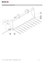
9. IMPLEMENT UNHITCHING / HITCHING - Cu, C1 and C2 LOADERS<br />
9.1 Implement unhitching<br />
Select a stable parking area.<br />
Position the implement on the ground.<br />
Remove the split pins then the crowd ram-implement link<br />
pins 1 .<br />
Remove the split pins then the boom-implement link pins<br />
2 .<br />
9.2 Implement hitching<br />
Fit the boom-implement link pins, then the split pins 1 .<br />
Fit the crowd ram link pins, then the split pins 2 . Adjust the<br />
ram rod extension if necessary.<br />
10. IMPLEMENT LEVEL INDICATOR - <strong>C+</strong> <strong>loader</strong><br />
The implement level indicator is useful for implement repositioning. Efficient even while lowering the <strong>loader</strong>, it is adjustable<br />
according to the implement type.<br />
• 19, rue de Rennes • BP 83221 • F - 35690 ACIGNÉ<br />
Indicator<br />
Implement in position<br />
16 Modification reserved<br />
1<br />
2<br />
2<br />
1
11. 3 rd FUNCTION<br />
he front couplers mounted on the <strong>loader</strong> cross beam are used to<br />
feed an implementc/w grab or any other attachement which<br />
requires a DA extra function (option).<br />
The connection will be easier after the engine is turned off and the<br />
3rd function residual pressure is released.<br />
Crowd and press the green switch at the same time to operate the<br />
3rd service.<br />
12. MACH 2<br />
Back-up control to be pressed if the solenoid<br />
valve locks.<br />
The Mach 2 (option) enables to instantly plug any implement<br />
hydraulic function without any effort.<br />
The Mach 2 kit includes 600 mm hoses to feed the <strong>MX</strong> implements.<br />
• 19, rue de Rennes • BP 83221 • F - 35690 ACIGNÉ<br />
17 Modification reserved
13. SHOCK ELIMINATOR<br />
No shocks anymore when driving or when suddenly stop the<br />
<strong>loader</strong> during lowering (option).<br />
Suspension off<br />
Suspension on<br />
14. LOADER MAINTENANCE<br />
Caution<br />
Change the tractor hydraulic oil and filters regularly in accordance with the tractor<br />
manufacturer recommendations. Used oil does not lubricate, it also contributes to the<br />
damage of all hydraulic components (pump, valves, rams…).<br />
14.1 Clean the implement and the <strong>loader</strong> front after each use.<br />
CAUTION : some detergents may attack the paint and steel of the <strong>loader</strong>.<br />
14.2 Grease after each wash<br />
(grease eliminates water)<br />
and particularly after<br />
washing with a high<br />
pressure cleaner.<br />
• 19, rue de Rennes • BP 83221 • F - 35690 ACIGNÉ<br />
C1 and C2 <strong>loader</strong>s <strong>C+</strong> and Cu <strong>loader</strong>s<br />
18 Modification reserved
Check the following each month, and more frequently when used intensively:<br />
– Condition of the <strong>loader</strong> articulations. If necessary, replace the wear bushes and/or the pins.<br />
The wear bushes must be replaced if they are less than 1 mm thick.<br />
– The tractor’s hydraulic oil level and the sealing of the hydraulic system. If you notice any internal or external leaks on<br />
the hydraulic parts (rams, hoses, connectors, Mach, couplings, etc.), contact your dealer.<br />
– Condition of the hoses: replace them if you notice any small cracks or oil seepage.<br />
– Correct operation of the monolever (cables, play, locking, etc.).<br />
– Condition of the electric wiring. Please contact your dealer if there is any damage to connectors or cables.<br />
– Mechanical condition (any cracking, deformation, fretting on stops, play, parking stands, etc.). Please contact your<br />
dealer if there is any abnormal wear.<br />
Check the tightness of the bracket after 10, 50 hours then every 100 hours or when carring out tractor maintenance. In case of<br />
untightness, please contact your dealer.<br />
IMPORTANT:<br />
All the screws needing to be retightened must be inspected, changed if necessary, cleaned and smeared with loctite.<br />
Tighten the screws to the tightening torque specified in the table below.<br />
Use of a pneumatic spanner to tighten the screws on the tractor is forbidden.<br />
Tightening torque (Nm)<br />
Thread<br />
8.8<br />
Class of bolt<br />
10.9 12.9<br />
M 8 21 29 35<br />
M 10 42 58 70<br />
M 12 72 101 121<br />
M 14 114 160 193<br />
M 16 174 245 295<br />
M 18 240 340 405<br />
M 20 340 475 570<br />
M 22 455 640 765<br />
M 30 x 150 500<br />
M 40 x 150 500<br />
15. TRACTOR MAINTENANCE<br />
Pour les opérations d’entretien et de réglage du tracteur, il est vivement conseillé de dételer le chargeur.<br />
Le dételage du chargeur est une opération simple et rapide qui offre les meilleures garanties de sécurité et d’efficacité pour<br />
l’entretien du tracteur et du chargeur.<br />
For any maintenance operations made whilst<br />
the <strong>loader</strong> is the raised position, the <strong>loader</strong><br />
must be locked into position<br />
Close the tap fitted on the lifting coupler.<br />
• 19, rue de Rennes • BP 83221 • F - 35690 ACIGNÉ<br />
19 Modification reserved
16. SAFETY DEVICE ON LIFTING/CROWDING<br />
If the <strong>loader</strong>s lifting operation requires people to be in the close proximity, the hydraulic circuit of the <strong>loader</strong> must have safety<br />
device fitted to it.<br />
This in accordance with the standard EN 12525/A1, from July 2006.<br />
17. CONTROL<br />
Important: Never leave the tractor with <strong>loader</strong> in raised position.<br />
All spool valves produce an internal leak required for correct operation.<br />
17.1 On tractor valves<br />
Please report to the tractor’s instruction book.<br />
17.2 On <strong>MX</strong> valves:<br />
17.2.1 Security:<br />
Involuntary <strong>loader</strong> manoeuvre can be avoided. The<br />
<strong>MX</strong> joystick can be locked. See diagram.<br />
17.2.2 Lifting-crowding movements<br />
17.2.3 Other<br />
3 rd FUNCTION :<br />
Green button + Crowding.<br />
• 19, rue de Rennes • BP 83221 • F - 35690 ACIGNÉ<br />
Multifunction monolever<br />
<strong>C+</strong> and Cu <strong>loader</strong>s<br />
Monolever<br />
C1 and C2 <strong>loader</strong>s<br />
20 Modification reserved
18. GENERAL INFORMATION<br />
Each implement is designed for a specific use and has its own resistance limits.<br />
Land clearing and stump extraction are forbiden. Such work should be carried out by a specialist vehicle and is not possible<br />
for an agricultural <strong>loader</strong>.<br />
Use the tractor’s power to enter in the material to be moved rather than approaching it with speed, which will generate high<br />
stress on tractor and <strong>loader</strong>.<br />
When the load to be manoeuvred is too heavy, do not apply force to the hydraulic components. This also applies when rams<br />
are fully closed or extended. Please release the control lever.<br />
• 19, rue de Rennes • BP 83221 • F - 35690 ACIGNÉ<br />
21 Modification reserved
19. TECHNICAL SPECIFICATIONS<br />
(C)<br />
Length : ( A )<br />
Width : ( B )<br />
Height : ( C )<br />
Weight (Without option)<br />
Maximum height at implement pivot *<br />
Maximum height under horizontal bucket (1) #<br />
Maximum height under dumped bucket (2) #<br />
Digging depth #<br />
Dumping angle at maximum height (3) #<br />
Dumping angle on the ground (4) #<br />
Crowd angle (5) #<br />
(B)<br />
(A)<br />
Forward reach available for discharge (6) #<br />
Lift force at implement pivot * (Kg)<br />
Lift capacity at implement pivot over the entire lifting range * (Kg)<br />
• 19, rue de Rennes • BP 83221 • F - 35690 ACIGNÉ<br />
<strong>MX</strong> C1, C2 <strong>MX</strong> 20Cu <strong>MX</strong> 20<strong>C+</strong> <strong>MX</strong> 25Cu <strong>MX</strong> 25<strong>C+</strong> <strong>MX</strong> 30<strong>C+</strong><br />
1.20 m 1.45 m 1.45 m 1.60 m 1.60 m 1.75 m<br />
0.90 m 0.90 m 0.90 m 0.90 m 0.90 m 1.05 m<br />
1.05 m 1.05 m 1.05 m 1.20 m 1.20 m 1.25 m<br />
135 Kg<br />
(with implement)<br />
130 Kg 140 Kg 140 Kg 165 Kg 205 Kg<br />
1.92 m 2.15 m 2.15 m 2.45 m 2.45 m 2.60 m<br />
1.80 m 1.95 m 1.95 m 2.25 m 2.25 m 2.35 m<br />
1.50 m 1.60 m 1.60 m 1.90 m 1.90 m 2.00 m<br />
0.10 m 0.15 m 0.15 m 0.15 m 0.15 m 0.15 m<br />
40° 35° 68° 35° 68° 68°<br />
125° 90° 90° 115° 115° 122°<br />
30° 25° 45° 25° 45° 45°<br />
900 mm 850-950 mm 850-950 mm 950-1050 mm 950-1050 mm 1050-1150<br />
mm<br />
450 Kg 660 Kg 660 Kg 730 Kg 730 Kg 1400 Kg<br />
420 Kg 570 Kg 570 Kg 630 Kg 630 Kg 990 Kg<br />
Payload on pallet 0.50 m in front of the forks<br />
At ground level (Kg) 390 Kg 470 Kg 490 Kg 510 Kg 540 Kg 1250 Kg<br />
At 1 m height (Kg) 370 Kg 435 Kg 450 Kg 480 Kg 500 Kg 1100 Kg<br />
At 2 m height (Kg) – 395 Kg 410 Kg 425 Kg 450 Kg 930 Kg<br />
At maximum height (Kg) 350 Kg 375 Kg 390 Kg 410 Kg 425 Kg 710 Kg<br />
Lifting time (s)<br />
3 sec 4.5 sec 4.5 sec 4.5 sec 4.5 sec 3.8 sec<br />
Dumping time (s)<br />
3 sec 2.2 sec 2.2 sec 2.5 sec 2.5 sec 3.3 sec<br />
Data varies according to the type of tractor used.<br />
Specifications measured at 140 bar and a flow rate of 15 litres/min for <strong>MX</strong> C1 and C2.<br />
Specifications measured at 140 bar and a flow rate of 20 litres/min for <strong>MX</strong> 20Cu/20<strong>C+</strong> and <strong>MX</strong> 25Cu/25<strong>C+</strong>.<br />
Specifications measured at 180 bar and a flow rate of 30 litres/min for <strong>MX</strong> 30<strong>C+</strong>.<br />
# Indicated data are with a loose material bucket.<br />
* Values at ground level and at implement pivot are not considered to be working data.<br />
22 Modification reserved
DECLARATION OF CONFORMITY<br />
We manufacturer:<br />
<strong>MX</strong><br />
19,Rue de Rennes<br />
F - 35690 Acigné<br />
Declare that the product:<br />
<strong>MX</strong> C1, <strong>MX</strong> C2, <strong>MX</strong> 20Cu, <strong>MX</strong> 20<strong>C+</strong>, <strong>MX</strong> 25Cu, <strong>MX</strong> 25<strong>C+</strong>, <strong>MX</strong> 30<strong>C+</strong> <strong>loader</strong>s<br />
Comply with standard EN 12525, and its amendments A1 and A2, which presupposes<br />
compliance with the requirements of directive 2006/42 EC of the European Parliament<br />
and of the Council of 17 May 2006 on machinery.<br />
Acigné, the 30th of June 2011.<br />
Loïc Mailleux<br />
Technical Manager
19, rue de Rennes<br />
BP 83221<br />
F - 35690 ACIGNE<br />
Tél. : +33 (0)2 99 62 52 60<br />
Fax : +33 (0)2 99 62 50 22<br />
e-mail : contact@m-x.eu