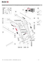
MX R28 MX R38
MX R28 MX R38
MX R28 MX R38

You also want an ePaper? Increase the reach of your titles
YUMPU automatically turns print PDFs into web optimized ePapers that Google loves.
User manual<br />
FRONT LINKAGE<br />
<strong>MX</strong> <strong>R28</strong><br />
<strong>MX</strong> <strong>R38</strong><br />
Please read carefully before using <strong>MX</strong><br />
front linkage<br />
UK 365177 AA -1011<br />
Original instructions
Dear users,<br />
Thanks you for confidence in our product. We are sure it will give you full satisfaction.<br />
By taking a few minutes to read this manual, you will be able to obtain the best results from your <strong>MX</strong> front linkage,<br />
extend its lifespan and work in complete safety.<br />
The front linkage user manual is a very important document, please keep it with you in order to be able to use it if<br />
required. Leave it available to any other user and give it to the next owner of this front linkage.<br />
Pictures and technical information included in this document may not correspond precisely to your front linkage;<br />
but the working conditions will be the same.
CONTENTS<br />
1. SAFETY REGULATIONS 6<br />
2. USAGE REGULATION 7<br />
3. SAFETY STICKERS 8<br />
4. IDENTIFICATION PLATE 8<br />
5. DESCRIPTION 9<br />
6. OPERATING POSITION 10<br />
7. IMPLEMENT HITCHING 12<br />
8. IMPLEMENT DISCONNECTING 13<br />
9. FOLDED ARMS POSITION 14<br />
10. REAR SUPPORT * 15<br />
11. PUSH BAR * 15<br />
12. SHOCK ELIMINATOR * 16<br />
13. FRONT POWER TAKE OFF (PTO) * 16<br />
14. ADDITIONAL FRONT HYDRAULIC LINE * 17<br />
15. 3-WAY SELECTOR * 18<br />
16. EXTERNAL CONTROL * 19<br />
17. HYDRAULIC TOP-LINK BAR * 19<br />
18. ACCESSORIES 19<br />
19. CONTROL 20<br />
20. MAINTENANCE 21<br />
21. TECHNICAL SPECIFICATIONS 22<br />
* According to equipment
The operator must read this manual before using the product for the<br />
first time.<br />
• 19, rue de Rennes • BP 83221 • F - 35690 ACIGNÉ<br />
Familiarise yourself with:<br />
— Safety and operating regulations.<br />
— Hitching and unhitching of the implement;<br />
— Full use of the controls.<br />
5 Modification reserved
1. SAFETY REGULATIONS<br />
— The tractor/loader/linkage assembly must only be driven by someone who is trained and experienced.<br />
— When the tractor is fitted with a front linkage and loader, the user has to unhitch the loader before to using the <strong>MX</strong> front<br />
linkage (please see the loader instruction book for the unhitching proceedure).<br />
— CAUTION : before using of the front loader, please check the front linkage is locked (with the hydraulic tap), and the arms<br />
are folded or removed (see chapter "folded arms position").<br />
— Control the front linkage only from the driver’s seat, or from the external remote control supplied by <strong>MX</strong>. Do not let go of the<br />
controls until the movements are complete.<br />
— The controls for operating the front linkage must be of the "continued action" type with the exception of the lift floating<br />
position which can be maintained in its position by a notching system.<br />
— Do not leave the seat before locking the controls to prevent any movement.<br />
— It is compulsory to ensure that nobody is in the area while the front linkage and tractor are in use.<br />
— The transport or elevation of persons using the front linkage is forbidden..<br />
— Before moving with a front implement fitted, check and ensure that the tractor-front implement assembly is stable by fitting<br />
a counter weight at the rear of the tractor. This should provide 20% of the gross weight (tractor-front implement) on the rear<br />
axle of the tractor for driving and working in the best safety conditions..<br />
— The maximum front axle safe load provided by the tractor’s manufacturer must not be exceeded.<br />
— The front tyres maximum safe load provided by the tyres’s manufacturer must not be exceeded.<br />
— Check regularly tyres pressure.<br />
— An implement hitched to the front linkage must be able to be lifted through the full range of linkage’s movement. Any excess<br />
load preventing this movement is strictly forbidden.<br />
— Before moving, the user must ensure that the front linkage is in good working order and can be used safely.<br />
— When driving on the road with a front implement, the front linkage must always be in a raised position and the road<br />
regulations must be respected (dimensions, signalling on implement, etc.)<br />
— When driving on the road without a front implement, the front linkage must be set to the transport position (see section<br />
"Setting the front linkage to transport position")<br />
— Whenever the tractor is stopped for a short or long time, the engine must be switched off and the linkage lowered.<br />
— The tractor must never be towed from an anchoring point on the front linkage.<br />
— Regularly check the presence of safety pins and bolts. Do not replace with any other object such as nails, wire, etc.<br />
— Any activity relating to defect investigation ( diagnosis ) and / or disassembly of parts may only be undertaken by an<br />
accredited professional who shall assure his safety and the protection of the environment in which the actvity is conducted.<br />
• 19, rue de Rennes • BP 83221 • F - 35690 ACIGNÉ<br />
Caution !<br />
— The front linkage’s hydraulic circuit is designed to have a maximum service pressure of 200 bar.<br />
— never modify the hose connections<br />
— The assembly of an <strong>MX</strong> front linkage which excludes the recommendations in the <strong>MX</strong> price list in force at the purchase date,<br />
cancels the <strong>MX</strong> guarantee on all the equipment supplied.<br />
— Any modification to a section of any <strong>MX</strong> equipment (rams, arms, pivot frame, etc.) or the use of an implement or element<br />
installed on the <strong>MX</strong> front linkage from foreign origin, cancels the <strong>MX</strong> guarantee for all equipment supplied.<br />
— Use only <strong>MX</strong> original spare parts. Do not modify your <strong>MX</strong> Front linkage yourself or have another person modify them, without<br />
prior written agreement from <strong>MX</strong>. Failure to respect these regulations may make the Front linkage dangerous. <strong>MX</strong> will<br />
disclaim all responsibility in the event of damage or injury.<br />
— The guarantee is immediately invalid when the instructions for use, and the <strong>MX</strong> Front linkage maintenance schedule<br />
outlined in the "User Manual" are not observed.<br />
6 Modification reserved
2. USAGE REGULATION<br />
The front linkage is designed for implements which comply with the hitching dimensions defined in standard ISO 8759-1 for<br />
category II.<br />
The distance of the implement’s hitch points must be<br />
825 mm (dimension A) with a linkage pin of 28 mm<br />
diameter.<br />
The vertical height of the implement must be 610 mm<br />
(dimension H).<br />
Hitching an implement on which dimension ‘H’ is less than that shown places excess strain on the top link and may<br />
damage it.<br />
Hitching an implement with a dimension greater than H can damage the front of the tractor (bonnet, front guard,<br />
etc.) during the lifting operation.<br />
2.1 Implement/link point distance and ground work.<br />
The hitched implement must be fixed as close as possible to the hook-up points on the front linkage. In actual fact, the greater<br />
the front overhang, the higher the stresses on the front linkage (leverage). The more compact the implement fixing, the less<br />
strain there is on the equipment. Use of a compact implement also improves the lifting performances.<br />
For pushing work (implements of the soil decompaction or dozer blade type for instance), it is strongly recommended that a<br />
push bar be fitted to reinforce the tractor from the front linkage to the rear trumpet housings.<br />
Caution !<br />
Recommendations for fixing the implement, and working on the ground, must be strictly complied with. Any deviation<br />
from the requirements described above may cause serious damage, for which <strong>MX</strong> cannot be held liable.<br />
• 19, rue de Rennes • BP 83221 • F - 35690 ACIGNÉ<br />
7 Modification reserved
3. SAFETY STICKERS<br />
Safety stickers are located on the front linkage. Keep them readable and clean, and change them if damaged.<br />
4. IDENTIFICATION PLATE<br />
19, rue de Rennes F - 35690 ACIGNÉ<br />
Désignation/<br />
Designation<br />
Type / Model / Typ<br />
N˚ de série<br />
Serial number<br />
Seriennummer<br />
Poids à vide<br />
Unloaded weight / Leergewicht<br />
Année / Year<br />
• 19, rue de Rennes • BP 83221 • F - 35690 ACIGNÉ<br />
kg<br />
328462<br />
3T Maxi<br />
The identification plate is located on the right hand side of the headstock.<br />
The serial number and front linkage type which are indicated on this plate might be requested when requiring spare parts or<br />
technical assistance.<br />
8 Modification reserved
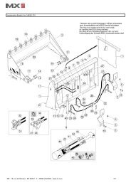
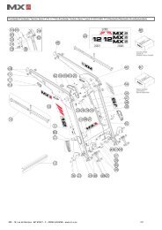
5. DESCRIPTION<br />
9<br />
4<br />
8<br />
3<br />
1: Right arm<br />
2: Left arm<br />
3: Arm pin<br />
4: Linkage frame<br />
5: Top-link yoke<br />
6: Top-link bar<br />
7: Lever locknut<br />
8: Hitch yoke<br />
9: Ram<br />
10: Frame<br />
11: Coupler<br />
12: Ball end<br />
• 19, rue de Rennes • BP 83221 • F - 35690 ACIGNÉ<br />
1<br />
10<br />
5<br />
6<br />
7<br />
2<br />
11<br />
12<br />
9 Modification reserved
6. OPERATING POSITION<br />
Caution<br />
This operation must be carried out by the driver who must leave the seat and<br />
ensure all manoevres are forbidden while he is working on the front linkage.<br />
6.1 Choose a flat and stable area.<br />
Pull the parking brake. Turn off the engine.<br />
6.2 Leave the cab and remove the L.H. arm locking pin.<br />
6.3 Support the L.H. arm and remove the pin.<br />
• 19, rue de Rennes • BP 83221 • F - 35690 ACIGNÉ<br />
10 Modification reserved
6.4 Swing the arms forwards to the desired position<br />
Position 1 : Fixed position 1.<br />
Position 2 : Fixed position 2.<br />
Position 3 : Floating position.<br />
Arm in floating position. The implement follows the contours of<br />
the ground.<br />
6.5 Put the pin back in position, and lock with the locking pin.<br />
6.6 Repeat the items 6.2 à 6.5 for the right arm.<br />
6.7 Open the stop valve.<br />
• 19, rue de Rennes • BP 83221 • F - 35690 ACIGNÉ<br />
Fermé Closed Open<br />
Ouvert<br />
11 Modification reserved
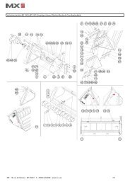
7. IMPLEMENT HITCHING<br />
Caution<br />
This operation must be carried out by the driver who must leave the seat and<br />
ensure all manoevres are forbidden while he is working on the front linkage.<br />
The linkage is in working position.<br />
7.1 Open the locking catches on the hitching hooks and hitch up the<br />
implement.<br />
Check that the implement is fitted with suitable coupling balls<br />
secured with locking pins.<br />
7.2 Hitch the top link bar to the mast of the front implement.<br />
7.3 Set the length of the top link bar to obtain the required movements<br />
from the front implement.<br />
Lock the adjustment of the bar by means of the lever locknut.<br />
• 19, rue de Rennes • BP 83221 • F - 35690 ACIGNÉ<br />
Checking before work<br />
— Test the lifting by checking that the tractor/front implement combination works correctly. Particularly check the space<br />
between the top link bar and the tractor’s engine bonnet.<br />
— Check that all the pins and locking pins are fitted and locked correctly.<br />
— Check the locking status of the hitching hooks (the catches must be retracted correctly)<br />
12 Modification reserved
8. IMPLEMENT DISCONNECTING<br />
Caution<br />
This operation must be carried out by the driver who must leave the seat and<br />
ensure all manoevres are forbidden while he is working on the front linkage.<br />
8.1 Lay the implement on some flat stable ground. Operate the<br />
tractor’s handbrake.<br />
8.2 Free the top link bar from the mast of the front implement.<br />
8.3 Reposition the upper link bar on to the front linkage frame.<br />
8.4 Unlock the hitching hooks and lower the linkage arms to release<br />
the implement.<br />
• 19, rue de Rennes • BP 83221 • F - 35690 ACIGNÉ<br />
13 Modification reserved
9. FOLDED ARMS POSITION<br />
Caution<br />
This operation must be carried out by the driver who must leave the seat and<br />
ensure all manoevres are forbidden while he is working on the front linkage.<br />
9.1 Choose a flat and stable area. Raise the front linkage arms.<br />
Apply the parking brake and shut off the engine.<br />
9.2 Close the stop valve.<br />
9.3 Hold the R.H. arm and remove the pin.<br />
• 19, rue de Rennes • BP 83221 • F - 35690 ACIGNÉ<br />
Closed Fermé Open<br />
Ouvert<br />
14 Modification reserved
9.4 Swivel the arm towards the bac and put the pin and the locking<br />
pin back in position.<br />
9.5 Repeat the items 9.3 et 9.4 for the left arm.<br />
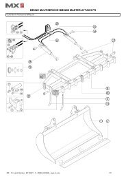
10. REAR SUPPORT *<br />
This structure is located under the tractor and it<br />
reinforces the tractor from the clutch bell housing<br />
to the rear trumpet housings.<br />
11. PUSH BAR *<br />
This attachment is located under the tractor,<br />
providing it with overall reinforcement from the<br />
front linkage to the rear trumpet housings.<br />
This equipment is strongly<br />
recommended for any heavy<br />
pushing work (e.g.: plough, soil<br />
decompaction implement, dozer blade, etc.).<br />
* According to equipment<br />
• 19, rue de Rennes • BP 83221 • F - 35690 ACIGNÉ<br />
15 Modification reserved
12. SHOCK ELIMINATOR *<br />
The shock absorber function requires that:<br />
— The minimum load for Shock Eliminator efficiency corresponds to<br />
20% of the linkage max. capacity.<br />
NOTE : The greater the load, the smaller the shock absorber travel<br />
must be.<br />
— The linkage is never at its maximum height. To attain the shockabsorbed<br />
transport position, the linkage must be lowered slightly<br />
starting from the upper position.<br />
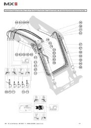
13. FRONT POWER TAKE OFF (PTO) *<br />
SAFETY REGULATIONS AND RECOMMENDATIONS REGARDING THE FRONT PTO<br />
— Never start the engine with the power take-off engaged.<br />
— Before hitching the implement, check that the implement’s direction<br />
of rotation is compatible with the front power take-off.<br />
— Check to ensure that the speed and power rating of the implement are<br />
matched to the power take-off. Otherwise, the implement must not be<br />
hitched and connected. (refer to the section "Technical specifications").<br />
— Do not use a high inertial load implement without a PTO overrun<br />
clutch.<br />
— Check and adapt the length of the transmission shaft between the<br />
implement and the front power take-off.<br />
— The universal joint of the transmission shaft must be fitted with suitable<br />
protection (complying with the standard ISO/DIS 5673-1).<br />
— Never lift or lower the front linkage with the power take-off under load.<br />
— Check the a and ß angles of the implement’s universal joint and the<br />
power take-off. Adjust the length of the top link to make these angles<br />
approximately equal (see diagram opposite). The limit value of the a<br />
and ß angles depends on the type of universal joint used (refer to the<br />
universal joint manufacturer’s user manual).<br />
— The engine must be stopped for any maintenance on the implement for which hydraulic must be locked.<br />
— Each time the power take-off is used, grease the sliding section of the shaft and the universal joint spiders beforehand.<br />
— Never make any changes to the electrical connections.<br />
— Observe the maintenance instructions (refer to the section "Maintenance").<br />
— The safety instructions in this manual are not to be construed as a replacement for safety regulations, insurance requirements<br />
or national and local legislation. Ensure your machine is fitted with the correct equipment as required by law and local<br />
regulations.<br />
* According to equipment<br />
• 19, rue de Rennes • BP 83221 • F - 35690 ACIGNÉ<br />
Leergewicht<br />
16 Modification reserved<br />
α<br />
β
Caution<br />
This operation must be carried out by the driver who must leave the seat and<br />
avensure all manoevres are forbidden while he is working on the front linkage.<br />
13.1 Hitch up the implement (refer to the section "Hitching a front<br />
implement" in this manual).<br />
13.2 Connect the PTO shaft to the front power take-off.<br />
The engine must be stopped.<br />
13.3 The power take-off is engaged and disengaged by pressing the<br />
switch located in the cab.<br />
The engine speed must never exceed 1200rpm when<br />
starting up the power take-off.<br />
13.4 Increase engine speed to 2100 rpm in order to attain the<br />
rotational speed required by the implement (i.e. 1000 rpm).<br />
13.5 After using the power take-off, disengage it using the same<br />
switch located in the cab.<br />
14. ADDITIONAL FRONT HYDRAULIC LINE *<br />
This supplies a hydraulic unit in front of the linkage.<br />
14.1 Connect the hydraulic hoses of the implement to the 1/2" female<br />
couplings. Release the pressure in the hydraulic system to<br />
make connecting the hoses easier.<br />
14.2 Control the hydraulic line using the tractor’s control valve or the<br />
<strong>MX</strong> control valve (refer to the "control" section).<br />
* According to equipment<br />
• 19, rue de Rennes • BP 83221 • F - 35690 ACIGNÉ<br />
Checking before work<br />
— Check that the tractor, implement and transmission shaft interact correctly throughout the full lifting stroke before<br />
engaging the power take-off.<br />
17 Modification reserved
15. 3-WAY SELECTOR *<br />
This selector, which is located behind the cab, enables the front linkage operating mode to be selected to suit your<br />
application with a single movement.<br />
There are 3 operating modes:<br />
15.1 "Locking" operation<br />
Usage: this mode is used when the <strong>MX</strong> front linkage is not being<br />
used or for travelling long distances with an implement or a<br />
weight (safety in transit).<br />
Plus, it enables the couplings at the rear of the tractor to be freed<br />
up for another powered implement.<br />
Description: the <strong>MX</strong> front linkage hydraulic system is locked<br />
out. The linkage arms can no longer be raised or lowered.<br />
Do the following: turn the levers as shown in the photo opposite.<br />
15.2 "Double-acting" operation<br />
Usage: this mode is used mainly when hitching up an implement<br />
(lowering linkage arms) and for working the soil with a bulldozer<br />
blade for instance.<br />
Description: the rams on the <strong>MX</strong> front linkage are pressurised<br />
on both lifting and lowering.<br />
Do the following: turn the levers as shown in the photo opposite.<br />
15.3 "Single-acting" operation<br />
Usage: this mode is used mainly with a front-end mowers or<br />
with an implement fitted with depth wheels.<br />
Description: the rams on the <strong>MX</strong> front linkage are pressurised<br />
on lifting, but lowering takes place through gravity (unpressurised)<br />
due to the weight of the implement. This absence of pressure on<br />
lowering ensures the implement rests unconstrained on the<br />
ground. This protects the implement.<br />
Do the following: turn the levers as shown in the photo opposite.<br />
— The levers must always be turned fully to either stop<br />
* According to equipment<br />
• 19, rue de Rennes • BP 83221 • F - 35690 ACIGNÉ<br />
Caution<br />
— Switching from Single-acting to Double-acting operation (and vice versa) must not be carried out before releasing the<br />
hydraulic pressure<br />
18 Modification reserved
16. EXTERNAL CONTROL *<br />
This unit fitted with 2 buttons is located on the front linkage and controls<br />
raising and lowering of the arms when hitching an implement.<br />
A second external control can be fitted on the front linkage to operate<br />
another hydraulic function (e.g.: hydraulic top link).<br />
17. HYDRAULIC TOP-LINK BAR *<br />
This system enables implement tilt to be adjusted from the driver’s seat.<br />
18. ACCESSORIES<br />
A number of attachments for <strong>MX</strong> front linkages are shown below.<br />
— Weight-carrier triangle<br />
This attachment enables the tractor’s original weights and weightcarriers<br />
to be picked up.<br />
* According to equipment<br />
• 19, rue de Rennes • BP 83221 • F - 35690 ACIGNÉ<br />
19 Modification reserved
— Counterweights<br />
Various capacities ranging from 400 to 1,400 kg are on offer for<br />
optimum stability of the tractor-implement combination.<br />
These weights can be hitched either on the front linkage or on the<br />
rear linkage.<br />
19. CONTROL<br />
19.1 With the original control valve fitted on the tractor. Refer to the<br />
user instructions for the tractor.<br />
19.2 With the <strong>MX</strong> control valve<br />
19.2.1 Raising and lowering the <strong>MX</strong> front linkage.<br />
Move the <strong>MX</strong> monolever forwards or backwards.<br />
19.2.2 Controlling the auxiliary hydraulic line (depending on the<br />
fittings). Move the <strong>MX</strong> monolever to the right and left.<br />
In order to operate a second auxiliary hydraulic line, press and<br />
hold the green button on the monolever handle and move it to<br />
the left or to the right.<br />
• 19, rue de Rennes • BP 83221 • F - 35690 ACIGNÉ<br />
400 kg weight 600 kg weight<br />
900 kg weight 900 kg auto weight<br />
1,400 kg weight<br />
20 Modification reserved
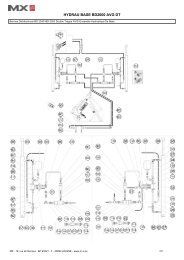
20. MAINTENANCE<br />
Grease every 10 hours and after each wash (water eliminates grease)<br />
and particularly after washing with a high pressure cleaner. See<br />
lubricating points below.<br />
Check tightness of the nuts and bolts after 10 and 50 hours of operation,<br />
then every 100 hours.<br />
Before and after each use, check that there are no hydraulic leaks and<br />
The linkage frame is fitted with two wear bushes in the event of excessive<br />
play (±2 mm) replace them with new <strong>MX</strong> wear bushes.<br />
Front PTO :<br />
After 50 and then after every 100 hours work (at least once per year):<br />
— Drain the oil and replace the filter with a new genuine <strong>MX</strong> one (see<br />
filter removal procedure below).<br />
— Next, refill the housing with oil up to the level shown opposite.<br />
Recommended oil type: SHELL HARVELLA TX 10W40<br />
NOTE : The oil level of the power take-off unit must regularly be checked<br />
and topped up if required.<br />
Filter removal and refitting procedure<br />
Removing the filter:<br />
— Remove circlip (B) and cover (C).<br />
— Unscrew hollow bolt (D) from the pump and remove filter (A).<br />
Refitting the filter:<br />
— Refit filter (A) securing it with hollow bolt (D) ensuring it has been positioned<br />
correctly (illustration below).<br />
— Refit cover (C) and secure it with circlip (B).<br />
• 19, rue de Rennes • BP 83221 • F - 35690 ACIGNÉ<br />
UP<br />
UP<br />
OK 503736<br />
Oil change plug<br />
Oil filling plug<br />
Oil level<br />
A D C B<br />
21 Modification reserved
21. TECHNICAL SPECIFICATIONS<br />
• 19, rue de Rennes • BP 83221 • F - 35690 ACIGNÉ<br />
1<br />
2<br />
<strong>R28</strong> <strong>R38</strong><br />
Front linkage category 2<br />
Lifting power at couplers* 2800 Kg 3800 Kg<br />
Lifting power at implement center of gravity 610 mm from ball ends* 1800 Kg 3300 Kg<br />
Width between lifting arms 825 mm<br />
Lift arm height from ground*<br />
in lowest position (1) < 200 mm<br />
in highest position (2) > 900 mm<br />
Couplers Auto. Cat. 2 and 3N<br />
Balls end Cat. 2<br />
Top link / length Cat. 2 / 460 to 680 mm<br />
Front Power Take Off (PTO) **<br />
Maximum PTO power 150 hp<br />
Front PTO shaft speed 1000 rpm<br />
PTO shaft profile (DIN 9611) 1"3/8 - 6 splines<br />
* Average data. Variable according to the tractor specification.<br />
** Option not available on all tractor makes and models.<br />
22 Modification reserved
DECLARATION OF CONFORMITY<br />
The manufacturer :<br />
<strong>MX</strong><br />
19,Rue de Rennes<br />
F - 35690 Acigné<br />
declares that the following equipment :<br />
<strong>MX</strong> <strong>R28</strong>, <strong>R38</strong> front linkages<br />
comply with EC directive 2006/42 of the Council of European Parliament and of the<br />
council of 17th of May 2006 relating to machines.<br />
Acigné, 10th of January 2011.<br />
Loïc Mailleux<br />
Technical Director
19, rue de Rennes<br />
BP 83221<br />
F - 35690 ACIGNE<br />
Tél. : +33 (0)2 99 62 52 60<br />
Fax : +33 (0)2 99 62 50 22<br />
e-mail : contact@m-x.eu