User Manual - MX
User Manual - MX
User Manual - MX

You also want an ePaper? Increase the reach of your titles
YUMPU automatically turns print PDFs into web optimized ePapers that Google loves.
<strong>User</strong> <strong>Manual</strong><br />
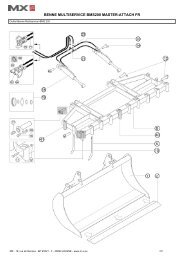
FRONT LINKAGE<br />
<strong>MX</strong> R12<br />
Read carefully before operating<br />
the <strong>MX</strong> front linkage<br />
UK 364001 AA - 1209<br />
Original instructions
Dear users,<br />
Thanks you for confidence in our product. We are sure it will give you full satisfaction.<br />
By taking a few minutes to read this manual, you will be able to obtain the best results from your <strong>MX</strong> front<br />
linkage, extend its lifespan and work in complete safety.<br />
The front linkage user manual is a very important document, please keep it with you in order to be able to use<br />
it if required. Leave it available to any other user and give it to the next owner of this front linkage.<br />
Pictures and technical information included in this document may not correspond precisely to your front linkage;<br />
but the working conditions will be the same.
TABLE OF CONTENTS<br />
1. SAFETY RULES 5<br />
2. OPERATING REQUIREMENTS 6<br />
3. SAFETY STICKERS 7<br />
4. IDENTIFICATION PLATE 7<br />
5. DESCRIPTION 8<br />
6. SETTING FRONT LINKAGE TO OPERATING POSITION 9<br />
7. HITCHING A FRONT IMPLEMENT 11<br />
8. UNHITCHING A FRONT IMPLEMENT 13<br />
9. SETTING FRONT LINKAGE TO TRANSPORT POSITION 14<br />
10. SHOCK ELIMINATOR 15<br />
11. 3-WAY SELECTOR 16<br />
12. FRONT POWER TAKE-OFF 17<br />
13. AUXILIARY HYDRAULIC LINE 18<br />
14. CONTROL 18<br />
15. MAINTENANCE 19<br />
16. TECHNICAL SPECIFICATIONS 20<br />
EC DECLARATION OF CONFORMITY 21<br />
Page
The user must read and understand this manual<br />
before first use.<br />
• 19, rue de Rennes BP 83221 F - 35690 ACIGNÉ<br />
Familiarise yourself with:<br />
— Safety rules and operating requirements.<br />
— Hitching and unhitching an implement.<br />
— Full use of the controls.<br />
4 Modification reserved
1. SAFETY RULES<br />
— The tractor – linkage combination must only be operated by trained and experienced personnel.<br />
— When the tractor is fitted with a front linkage and front-end loader, the user is required to unhitch the loader before using the <strong>MX</strong> front linkage<br />
(please refer to the loader user manual for the unhitching procedure).<br />
— CAUTION: before using the front-end loader in any way, check that the <strong>MX</strong> front linkage is locked hydraulically, and that the arms are folded.<br />
(see "Setting the front linkage to transport position" section).<br />
— Only operate the front linkage from the operators seat or by using the <strong>MX</strong> factory-supplied external controls. Operate the controls until<br />
movements are complete.<br />
— The controls for operating the front linkage must be of the "spring return" type with the exception of the floating position which may be held by<br />
a detent system.<br />
— Do not abandon the operator's seat unless operation of all controls have been locked.<br />
— Move all personnel out of the area in which the front linkage/implement is moving while it is in operation.<br />
— Carrying or lifting personnel using the front linkage is forbidden.<br />
— Before any use of a front implement, check and ensure that the tractor-front implement combination is stable by fitting a counterweight to the<br />
rear of the tractor. This should ensure that 20% of the gross weight (tractor-front implement) remains on the rear axle of the tractor for optimum<br />
safety while travelling and working.<br />
— The maximum front axle loading specified by the tractor manufacturer must not be exceeded.<br />
— The maximum loading on the front tyres specified by the tyre manufacturer must not be exceeded.<br />
— Check tyre pressures regularly.<br />
— An implement hitched to the front linkage must be capable of being lifted through the full travel of the linkage. Any excess load impeding this<br />
travel is strictly forbidden.<br />
— Before any operation, the user must ensure that the front linkage is in proper working order and can be used in complete safety.<br />
— When travelling on the road with a front implement, the front linkage must always be in a raised position and it is imperative that the regulations<br />
governing use on the public highway be observed (size, implement markings, etc.).<br />
— When driving on the road without a front implement, the front linkage must be set to the transport position (see "Setting the front linkage to<br />
transport position" section).<br />
— Whenever the tractor is stopped momentarily or for an extended period, the engine must be shut down and the linkage lowered.<br />
— Towing the tractor using the front linkage is permissible using the yoke provided for this purpose (Caution: do not exceed the towing force<br />
indicated on the sticker.<br />
— Check periodically to ensure that safety pins and bolts are in place. Do not replace them with any other items such as: nails, wire, etc.<br />
— Any work involving ascertaining defects (diagnostics) and/or disassembly of parts may only be undertaken by a skilled technician who will start<br />
with an assurance that the work will be carried out in complete safety for himself and his surroundings.<br />
19, rue de Rennes BP 83221 F - 35690 ACIGNÉ<br />
Caution!<br />
— The <strong>MX</strong> front linkage hydraulic system is designed to withstand a maximum operating pressure of 200 bar.<br />
— Never make any changes to the hose connections.<br />
— Any instance of <strong>MX</strong> front linkage being fitted which ignores the recommendations in the <strong>MX</strong> price list in force on the date of purchase will void<br />
<strong>MX</strong> warranty on the entire <strong>MX</strong> supply.<br />
— Any modification to any part of the <strong>MX</strong> supply (rams, arms, linkage frame, etc.) or use of a component installed on the <strong>MX</strong> front linkage which<br />
has not originated from <strong>MX</strong> will void <strong>MX</strong> warranty on the entire <strong>MX</strong> supply.<br />
— Use only genuine <strong>MX</strong> spare parts. Do not modify your <strong>MX</strong> front linkage yourself or or have it modified by anyone else, without applying for<br />
written authorisation from <strong>MX</strong> in advance. Failure to comply these rules may make your <strong>MX</strong> front linkage hazardous. <strong>MX</strong> cannot be held liable<br />
in any way in the event of damage or injury.<br />
— Warranty cover will cease immediately in the event of failure to observe the standards and instructions for use and maintenance of the <strong>MX</strong> front<br />
linkage as stipulated in the user manual.<br />
5 Modification reserved
2. OPERATING REQUIREMENTS<br />
2.1 Implement hitching<br />
The <strong>MX</strong> R12 front linkage is designed to be fitted with implements which comply with the hitch dimensions specified in<br />
standard ISO 730-1 for categories I and II.<br />
Implement hitch points are to be spaced at between 683<br />
and 825 mm (dimension A) with a 22 mm diameter<br />
linkage pin for cat. I and 28 mm for cat. II.<br />
The vertical height between the top and bottom hitch<br />
points on the implement is to be between 460 and<br />
610 mm (dimension H).<br />
Hitching an implement with a dimension H less than that specified above will overload the upper link bar,<br />
causing damage to it.<br />
Hitching an implement with dimension H in excess of that specified above can cause damage to the front of the<br />
tractor (bonnet, grille, etc.) on lifting.<br />
2.2 Front overhang and use on the ground<br />
The implement must be hitched as close as possible to the attachment points on the front linkage. In fact, the longitudinal<br />
overhang generates considerable stresses on the front linkage (due to leverage). The more compact the implement fixing,<br />
the less strain there will be on the equipment. Using a compact implement also improves lifting performance.<br />
This category of linkage is not intended for pushing work. Implements of the soil decompaction type are highly inadvisable<br />
in order to safeguard the structural integrity of the machine.<br />
19, rue de Rennes BP 83221 F - 35690 ACIGNÉ<br />
Caution!<br />
Requirements for implement hitching and for working on the ground must be strictly complied with. Any deviation from<br />
the requirements risks causing serious damage for which <strong>MX</strong> cannot be held liable.<br />
6 Modification reserved
3. SAFETY STICKERS<br />
A safety sticker is affixed to the front linkage. Keep it readable and clean; replace it if damaged.<br />
4. IDENTIFICATION PLATE<br />
501332<br />
1.5T Maxi<br />
The identification plate is located on the right-hand side of the front linkage frame.<br />
501332<br />
1.5T Maxi<br />
The serial number and front linkage model shown on this plate must be quoted in any request for spare parts information or<br />
technical assistance.<br />
19, rue de Rennes BP 83221 F - 35690 ACIGNÉ<br />
Ref.: 501332<br />
19, rue de Rennes<br />
F - 35690 ACIGNÉ<br />
Type / Model / Typ<br />
N˚ de série<br />
Serial number / Seriennummer<br />
Année de fabrication<br />
Year of manufacture / Baujahr<br />
Ref.: 320005<br />
7 Modification reserved
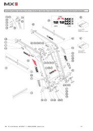
5. DESCRIPTION<br />
10<br />
5<br />
4<br />
3<br />
1<br />
1: Right-hand arm<br />
2: Left-hand arm<br />
3: Pin<br />
4: Adjustment handle<br />
5: Linkage frame<br />
6: Upper link yoke<br />
7: Top link<br />
8: Top link locknut<br />
9: Towing clevis<br />
10: Ram<br />
11: Frame<br />
12: Hitching hook<br />
13: Coupling ball<br />
19, rue de Rennes BP 83221 F - 35690 ACIGNÉ<br />
11<br />
6<br />
9<br />
7<br />
8<br />
8 Modification reserved<br />
2<br />
12<br />
13
6. SETTING FRONT LINKAGE TO OPERATING POSITION<br />
6.1 Choose a level and solid surface.<br />
The tractor engine is to be turned of and the hand brake<br />
applied.<br />
6.2 Leave the cab and remove the locking pin from the left-hand<br />
arm.<br />
6.3 Hold the left-hand arm and withdraw the pin.<br />
19, rue de Rennes BP 83221 F - 35690 ACIGNÉ<br />
Caution<br />
This operation must be carried out by the driver who must leave his seat and<br />
ensure all controls are locked out while he is working on the front linkage<br />
9 Modification reserved
6.4 Swing the arms forwards to the desired position.<br />
Position 1: fixed position.<br />
Position 2: floating position.<br />
Arm in floating position. The implement follows the contours<br />
of the ground.<br />
6.5 Refit the pin and secure it with the locking pin.<br />
6.6 Repeat operations 6.2 to 6.5 for the right-hand arm.<br />
6.7 Open the isolator valve.<br />
19, rue de Rennes BP 83221 F - 35690 ACIGNÉ<br />
Fermé Closed<br />
Open Ouvert<br />
10 Modification reserved
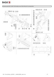
7. HITCHING A FRONT IMPLEMENT<br />
The linkage is in the operating position.<br />
7.1 Set the spacing of the linkage arms to match the implement<br />
being hitched.<br />
Turn the adjustment handle located at the base of the left-hand<br />
arm clockwise in order to adjust the spacing.<br />
Repeat the procedure with the right-hand arm.<br />
Ensure the left and right-hand arms are set identically to<br />
enable the implement to be centred on the tractor.<br />
7.2 Open the locking catches on the hitching hooks and hitch up<br />
the implement.<br />
Check that the implement is fitted with suitable coupling balls<br />
secured with locking pins.<br />
19, rue de Rennes BP 83221 F - 35690 ACIGNÉ<br />
Caution<br />
This operation must be carried out by the driver who must leave his seat and<br />
ensure all controls are locked out while he is working on the front linkage<br />
11 Modification reserved
.<br />
7.3 Hitch the top link bar on to the front implement.<br />
7.4 Set the length of the top link bar to obtain the desired geometry<br />
for the front implement.<br />
Lock the adjustment of the bar by means of the lever locknut.<br />
Checks to be carried out before starting work<br />
— Carry out a lift test checking that the tractor and front implement interact correctly. Pay particular attention to<br />
checking the gap between the top link bar and the bonnet of the tractor.<br />
— Check that all pins and locking pins are fitted and secured correctly.<br />
— Check the locking status of the hitching hooks (the catches must be retracted correctly)<br />
19, rue de Rennes BP 83221 F - 35690 ACIGNÉ<br />
12 Modification reserved
8. UNHITCHING A FRONT IMPLEMENT<br />
8.1 Place the front implement on level and solid ground. Apply the<br />
tractor handbrake.<br />
8.2 Release the top link bar from the front implement bracket.<br />
8.3 Reposition the upper link bar on to the front linkage frame.<br />
8.4 Unlock the hitching hooks and lower the linkage arms to<br />
release the implement.<br />
19, rue de Rennes BP 83221 F - 35690 ACIGNÉ<br />
Caution<br />
This operation must be carried out by the driver who must leave his seat and<br />
ensure all controls are locked out while he is working on the front linkage<br />
13 Modification reserved
9. SETTING FRONT LINKAGE TO TRANSPORT POSITION<br />
9.1 Choose a level and solid surface. Raise the front linkage arms.<br />
Stop the tractor engine and apply the handbrake.<br />
9.2 Shut the isolator valve.<br />
9.3 Remove the locking pin while holding the right-hand arm.<br />
19, rue de Rennes BP 83221 F - 35690 ACIGNÉ<br />
Caution<br />
This operation must be carried out by the driver who must leave his seat and<br />
ensure all controls are locked out while he is working on the front linkage<br />
Fermé Closed<br />
Open Ouvert<br />
14 Modification reserved
9.4 Swing the right-hand arm rearwards and refit the pin and<br />
locking pin.<br />
9.5 Repeat operations 9.3 and 9.4 for the left-hand arm.<br />
9.6 Turn the arm adjustment handles in order to reduce the<br />
spacing between the arms to the minimum distance.<br />
10. SHOCK ELIMINATOR *<br />
Some advice on using the Shock Eliminator.<br />
The shock absorbing function requires that:<br />
— The minimum load for the Shock Eliminator to be effective is<br />
equal to 20% of the maximum linkage capacity.<br />
Note: The higher the load, the shorter the shock absorbing<br />
stroke.<br />
— The linkage is never in the fully raised position. For optimum<br />
shock absorption, the linkage should be lowered slightly from the<br />
fully raised position.<br />
* depending on configuration<br />
19, rue de Rennes BP 83221 F - 35690 ACIGNÉ<br />
15 Modification reserved
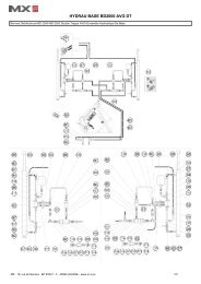
11. 3-WAY SELECTOR *<br />
This selector, which is located behind the cab, enables the front linkage operating mode to be selected to suit your<br />
application with a single movement.<br />
There are 3 operating modes:<br />
11.1 "Locking" operation<br />
Usage: this mode is used when the <strong>MX</strong> front linkage is not<br />
being used or for travelling long distances with an implement<br />
or a weight (safety in transit).<br />
Plus, it enables the couplings at the rear of the tractor to be<br />
freed up for another powered implement.<br />
Description: the <strong>MX</strong> front linkage hydraulic system is locked<br />
out. The linkage arms can no longer be raised or lowered.<br />
Do the following: turn the levers as shown in the photo<br />
opposite.<br />
11.2 "Double-acting" operation<br />
Usage: this mode is used mainly when hitching up an<br />
implement (lowering linkage arms) and for working the soil<br />
with a bulldozer blade for instance.<br />
Description: the rams on the <strong>MX</strong> front linkage are pressurised<br />
on both lifting and lowering.<br />
Do the following: turn the levers as shown in the photo<br />
opposite.<br />
11.3 "Single-acting" operation<br />
Usage: this mode is used mainly with a front-end mowers or<br />
with an implement fitted with depth wheels.<br />
Description: the rams on the <strong>MX</strong> front linkage are pressurised<br />
on lifting, but lowering takes place through gravity<br />
(unpressurised) due to the weight of the implement. This<br />
absence of pressure on lowering ensures the implement rests<br />
unconstrained on the ground. This protects the implement.<br />
Do the following: turn the levers as shown in the photo<br />
opposite.<br />
— The levers must always be turned fully to either stop<br />
* depending on configuration<br />
19, rue de Rennes BP 83221 F - 35690 ACIGNÉ<br />
Caution<br />
— Switching from Single-acting to Double-acting operation (and vice versa) must not be carried out before releasing<br />
the hydraulic pressure<br />
16 Modification reserved
12. FRONT POWER TAKE-OFF *<br />
SAFETY RULES AND RECOMMENDATIONS IN RESPECT OF<br />
THE POWER TAKE-OFF<br />
— Never start the engine with the power take-off engaged.<br />
— Before hitching the implement, check that the direction of rotation for the implement is<br />
compatible with the front power take-off.<br />
— Check whether the speed and power of the implement are matched to the power takeoff.<br />
Otherwise, the implement must not be hitched and connected (see specifications,<br />
page 19).<br />
— Check the length of the PTO shaft between the implement and the front power take-off<br />
and adapt it accordingly.<br />
— The PTO shaft must be fitted with a suitable guard (complying with the standard ISO/<br />
DIS 5673-1).<br />
— Never lift or lower the front linkage with the power take-off under load.<br />
— Check angles and of the implement and power take-off universal joints. Adjust the<br />
top link bar to make these angles approximately equal (see diagram opposite). The<br />
maximum values for angles and will vary according to the type of universal joint used<br />
(please refer to the universal joint manufacturer's user manual).<br />
— Any maintenance on the implement must be carried out with the engine shut down and<br />
the implement completely at rest.<br />
— Each time the power take-off is used, grease the sliding section of the shaft and the<br />
universal joint spiders beforehand.<br />
— Never make any changes to the electrical connections.<br />
— Observe the maintenance instructions on page 19.<br />
— The safety instructions in this manual are not to be construed as a replacement for<br />
safety regulations, insurance requirements or national and local legislation. Ensure your<br />
machine is fitted with the correct equipment as required by law and local regulations.<br />
12.1 Hitch up the implement (refer to the section "Hitching a front<br />
implement" in this manual).<br />
12.2 Connect the PTO shaft to the front power take-off.<br />
The tractor engine must be stopped.<br />
12.3 Start the tractor up again and engage the front power take-off<br />
using the switch fitted in the cab.<br />
Engine speed must not exceed 1200 rpm at any<br />
time when engaging the power take-off.<br />
* Depending on configuration<br />
19, rue de Rennes BP 83221 F - 35690 ACIGNÉ<br />
Caution<br />
This operation must be carried out by the driver who must leave his seat and<br />
ensure all controls are locked out while he is working on the front linkage<br />
17 Modification reserved<br />
α<br />
β
12.4 Increase engine speed to 2100 rpm in order to attain the<br />
rotational speed required by the implement (i.e. 1,000 rpm).<br />
12.5 After using the power take-off, disengage it using the same<br />
switch located in the cab.<br />
13. AUXILIARY HYDRAULIC LINE *<br />
This supplies a hydraulic unit in front of the linkage.<br />
13.1 Connect the hydraulic hoses of the implement to the ½" female<br />
couplings. Release the pressure from the hydraulic system to<br />
make the connection of the hoses easier.<br />
13.2 Operate the hydraulic line using the tractor or the <strong>MX</strong> control<br />
valve. (Refer to the "control" section in this manual).<br />
14. CONTROL<br />
14.1 Using the factory-fitted control valve on the tractor. Refer to the<br />
user manual for the tractor.<br />
14.2 Using the <strong>MX</strong> loader control valve.<br />
14.2.1 Raising and lowering the <strong>MX</strong> front linkage. Move the <strong>MX</strong><br />
monolever handle forwards and backwards.<br />
14.2.2 Operating the auxiliary hydraulic line (depending on<br />
configuration). Move the <strong>MX</strong> monolever handle to the left or<br />
to the right.<br />
In order to operate a second auxiliary hydraulic line, press<br />
and hold the green button on the monolever handle and<br />
move it to the left or to the right.<br />
* Depending on configuration<br />
19, rue de Rennes BP 83221 F - 35690 ACIGNÉ<br />
Checks to be carried out before work<br />
— Check that the tractor, implement and transmission shaft interact correctly throughout the full lifting stroke before<br />
engaging the power take-off.<br />
18 Modification reserved
15. MAINTENANCE<br />
Lubricate every 10 hours and after each wash (water drives grease<br />
out) and particularly after washing with a pressure washer. See<br />
lubrication points opposite.<br />
Check fasteners for tightness after 10 and 50 hours of operation, every<br />
100 hours thereafter, keeping to the recommended tightening torque.<br />
On each occasion, check before and after use for any hydraulic leaks<br />
which might have appeared and that the pins and locking pins are all<br />
fitted.<br />
The linkage frame and rams are fitted with wear bushes. If there is<br />
excessive play (approx. 2 mm), replace them with new genuine <strong>MX</strong><br />
bushes.<br />
Front power take-off:<br />
After the first 50 hours and every 500 tractor operating hours thereafter<br />
(or once a year):<br />
— Drain the oil and replace the filter with a new genuine <strong>MX</strong> one<br />
(see filter removal procedure below).<br />
— Next, refill the housing with oil up to the level shown opposite.<br />
Recommended oil type: SHELL HARVELLA TX 10W40<br />
NOTE: check power take-off housing oil level regularly and top up as<br />
necessary.<br />
Filter removal and refitting procedure<br />
Removing the filter:<br />
— Remove circlip (B) and cover (C).<br />
— Unscrew hollow bolt (D) from the pump and remove filter (A).<br />
Refitting the filter:<br />
— Refit filter (A) securing it with hollow bolt (D) ensuring it has been<br />
positioned correctly (illustration below).<br />
— Refit cover (C) and secure it with circlip (B).<br />
19, rue de Rennes BP 83221 F - 35690 ACIGNÉ<br />
UP<br />
UP<br />
OK 503736<br />
Drain plug<br />
Filler plug<br />
Oil level<br />
A D C B<br />
19 Modification reserved
16. TECHNICAL SPECIFICATIONS<br />
* Average figures. They may vary in line with tractor specifications.<br />
** Option available dependent upon tractor - front linkage compatibility.<br />
19, rue de Rennes BP 83221 F - 35690 ACIGNÉ<br />
R12<br />
Front linkage category Cat. 1 to 2<br />
Lifting capacity at the end of the linkage arms* 1200 Kg<br />
Lifting capacity with the centre of gravity of the implement<br />
positioned 610 mm forward of the ball ends*<br />
950 Kg<br />
Theoretical arm spacing 665 to 895 mm<br />
Height of linkage arms off the ground*<br />
in lowered position<br />
in raised position<br />
750 mm<br />
Hitching hooks auto. Cat. 2/1<br />
Coupling balls Cat. 2<br />
Top link length<br />
Power take-off (PTO) **<br />
Cat. 2 / 460 to 680 mm<br />
Max. PTO power<br />
150 hp<br />
PTO output speed<br />
1000 rpm<br />
Direction of rotation (viewed from tractor seat)<br />
clockwise<br />
Output shaft profile (DIN 9611)<br />
1' 3/8" - 6 splines<br />
20 Modification reserved
DECLARATION OF CONFORMITY<br />
The manufacturer:<br />
<strong>MX</strong><br />
19, rue de Rennes<br />
F - 35690 Acigné<br />
declares that the following equipment :<br />
<strong>MX</strong> R12 front linkage<br />
complies with EC directive 2006/42 of the Council of European Parliament and of the<br />
council of 17th of May 2006 relating to machines.<br />
Acigné, 15th of December 2009.<br />
Loïc Mailleux<br />
Technical Director
19, rue de Rennes<br />
BP 83221<br />
F - 35690 ACIGNE<br />
Tel.: +33 (0)2 99 62 52 60<br />
Fax: +33 (0)2 99 62 50 22<br />
e-mail: contact@m-x.eu