
You also want an ePaper? Increase the reach of your titles
YUMPU automatically turns print PDFs into web optimized ePapers that Google loves.
<strong>User</strong> <strong>manual</strong><br />
LOADER<br />
<strong>MX</strong> T6<br />
<strong>MX</strong> T8<br />
<strong>MX</strong> T10<br />
<strong>MX</strong> T12<br />
<strong>MX</strong> T15<br />
<strong>MX</strong> T16<br />
Please read carefully before using <strong>MX</strong><br />
loader<br />
UK 360738 AE - 0411<br />
Original instructions
Dear users,<br />
Thanks you for confi dence in our product. We are sure it will give you full satisfaction.<br />
By taking a few minutes to read this <strong>manual</strong>, you will be able to obtain the best results from your <strong>MX</strong> loader, extend<br />
its lifespan and work in complete safety.<br />
The loader user <strong>manual</strong> is a very important document, please keep it with you in order to be able to use it if<br />
required. Leave it available to any other user and give it to the next owner of this loader.<br />
Pictures and technical information included in this document may not correspond precisely to your loader; but the<br />
working conditions will be the same.
CONTENTS<br />
1. SAFETY REGULATIONS 6<br />
2. SAFETY STICKERS 7<br />
3.IDENTIFICATION PLATE 7<br />
4. COUNTERWEIGHT 8<br />
5. LOADER UNHITCHING 9<br />
6. LOADER HITCHING 12<br />
7. IMPLEMENT UNHITCHING 14<br />
8. IMPLEMENT HITCHING 16<br />
9. IMPLEMENT CARRIER FRAME MODELS 18<br />
10. IMPLEMENT LEVEL INDICATOR 19<br />
11. SELF LEVELLING, PCH SYSTEM 20<br />
12. SHOCK ELIMINATOR SYSTEM 20<br />
13. CROWD SYSTEM SPEED RESTRICTOR 21<br />
14. ACS 21<br />
15. SCS 22<br />
16. SAFETY DEVICE ON LIFTING/CROWDING 23<br />
17. MAINTENANCE 23<br />
18. GENERAL INFORMATION 24<br />
19. CONTROL 25<br />
20. TECHNICAL SPECIFICATIONS 27<br />
DECLARATION OF CONFORMITY 29<br />
Page
The loader is a complex machine. The end user must read this<br />
instruction book before fi rst use.<br />
• 19, rue de Rennes • BP 83221 • F - 35690 ACIGNÉ<br />
Familiarise yourself with<br />
— Safety instructions.<br />
— Hitching and unhitching of the loader.<br />
— Hitching and unhitching of the implements.<br />
— Full use of the controls.<br />
5 Modifi cation reserved
1. SAFETY INSTRUCTIONS<br />
— Commander le chargeur exclusivement à partir du poste de conduite. Garder le contrôle des commandes jusqu’à la fi n des<br />
Control the loader only from the driver’s seat. Do not let go of the controls until the movements are complete.<br />
— Do not leave the seat before locking the controls to prevent any movement.<br />
— Never leave the tractor while its loader is lifted. Following loader use, park the tractor with the loader lowered to the ground.<br />
— It is compulsory to ensure that nobody is in the area while the loader is in use.<br />
— The operation must use the implement designed and recommended by <strong>MX</strong> for the work to be carried out.<br />
— The transport or elevation of persons using the loader is forbidden.<br />
— Ensure tractor stability by using a counterweight. Please check the information regarding the counterweight in this user<br />
<strong>manual</strong>.<br />
— Restrict all movements while the load is lifted as the tractor may become unbalanced.<br />
— The maximum front axle safe load provided by the tractor’s manufacturer must not be exceeded.<br />
— The maximum front tyres safe load provided by the tyres’s manufacturer must not be exceeded.<br />
— Check regularly tyres pressure.<br />
— Regularly check the presence of safety pins and bolts. Do not replace with any other object such as nails, wire, etc.<br />
— Hitch the loader only to a tractor fi tted with a roll-over protective structure (ROPS) or a falling object protective structure<br />
(FOPS). This should be in the protective position when using the loader.<br />
— Watch out for overhead electrical and telephone cables when manoeuvring with the loader in the raised position.<br />
— In compliance with the standard EN 12525, the controls for operating the loader and implements must be of the "sustained<br />
action" type with the exception of the lift fl oating position which can be maintained in its position by a notching system.<br />
— Any activity relating to defect investigation (diagnosis) and / or disassembly of parts may only be undertaken by an accredited<br />
professional who shall assure his safety and the protection of the environment in which the actvity is conducted, in particular<br />
in the event of an activity involving the loader staying in the lifted position.<br />
• 19, rue de Rennes • BP 83221 • F - 35690 ACIGNÉ<br />
CAUTION !<br />
— The loader’s hydraulic circuit is designed to have a maximum service pressure of 200 bar.<br />
— Never modify hose connections.<br />
— The breaking of the seals will result in the cancellation of the <strong>MX</strong> responsibility for all the equipment supplied.<br />
— The assembly of an <strong>MX</strong> loader which excludes the recommendations in the <strong>MX</strong> price list in force at the purchase date,<br />
cancels the <strong>MX</strong> guarantee on all the equipment supplied.<br />
— Any modifi cation to a section of any <strong>MX</strong> equipment (implements, loader, bracket, etc.) or the use of an implement or element<br />
installed on the <strong>MX</strong> loader of foreign origin, cancels the <strong>MX</strong> guarantee for all equipment supplied.<br />
— Use only <strong>MX</strong> original spare parts. Do not modify your <strong>MX</strong> loader or its accessories yourself or have another person modify<br />
them (mechanical, electrical, hydraulic, pneumatic characteristics), without prior written agreement from <strong>MX</strong>. Failure to<br />
respect these regulations may make the loader dangerous. <strong>MX</strong> will disclaim all responsibility in the event of damage or<br />
injury.<br />
— The guarantee is immediately invalid when the instructions for use, and the <strong>MX</strong> loader maintenance schedule outlined in<br />
"<strong>User</strong> Manual" are not observed.<br />
6 Modifi cation reserved
2. SAFETY STICKERS<br />
Security stickers are located on the loader. Keep them readable and clean, and change them if damaged.<br />
3. IDENTIFICATION PLATE<br />
The identifi cation plate is located inside the LH arm, next to<br />
the implement level indicator.<br />
The serial number and loader type which are indicated on<br />
this plate might be requested when requiring spare parts or<br />
technical assistance.<br />
• 19, rue de Rennes • BP 83221 • F - 35690 ACIGNÉ<br />
19, rue de Rennes F - 35690 ACIGNÉ<br />
Désignation/<br />
Designation<br />
Type / Model / Typ<br />
N˚ de série<br />
Serial number<br />
Seriennummer<br />
Poids à vide<br />
Unloaded weight / Leergewicht<br />
504 303<br />
3<br />
Mettre dessin du tracteur + chargeur<br />
1<br />
Mettre dessin du tracteur + chargeur<br />
Mettre dessin du tracteur + chargeur<br />
Mettre dessin du tracteur + chargeur<br />
Mettre dessin du tracteur + chargeur<br />
Mettre dessin du tracteur + chargeur<br />
Mettre dessin du tracteur + chargeur<br />
Mettre dessin du tracteur + chargeur<br />
4 2<br />
Année / Year<br />
7 Modifi cation reserved<br />
kg<br />
1<br />
328462
4. COUNTERWEIGHT<br />
The stability of the tractor and loader can only be ensured with a counterweight on the rear of the tractor. This counterweight<br />
must ensure that a minimun of 20 % of the total weight (Tractor, loader, implement, maximum load and counterweight)<br />
is applied on the back axle of the tractor in order to work in a safe condition.<br />
Below is the calculation method which indicates the required counterweight (M).<br />
M ><br />
5 N b + I2 (P + N - 5 G)<br />
5 (I1 + I2) - I2<br />
G : Weight on the rear axle, wihtout counterweight, with an empty implement (kg).<br />
G1 : Weight on the front axle, without counterweight, with an empty implement (kg).<br />
b : Distance from the front axle to the implement centre of gravity (mm).<br />
I1 : Distance from rear linkage pins to the rear axle (mm).<br />
I2 : Wheelbase.<br />
N : Loader payload at 2 m (Kg).<br />
P : G + G1 (kg)<br />
M : Weight of the counterweight (kg).<br />
• 19, rue de Rennes • BP 83221 • F - 35690 ACIGNÉ<br />
8 Modifi cation reserved
5. LOADER UNHITCHING<br />
Caution<br />
This operation must be carried out by the driver who must leave the seat and<br />
ensure all manoeuvres are forbidden while he is working on the loader.<br />
The loader must always be coupled to an implement to unhitch it.<br />
5.1 Choose a fl at and stable area.<br />
5.2 Lower the loader with double acting in order to slightly lift<br />
the front axle of the tractor, with the implement horizontal<br />
to the ground. Operate in single acting mode, then back to<br />
neutral. The lift rams will be fi lled both sides with oil and<br />
involuntary movements of the loader will be limited when<br />
the loader has prolonged exposure to the sun and will<br />
ensure the hitching is correct.<br />
5.3 Pull the parking brake. Turn off the engine<br />
5.4 Get out of the tractor.<br />
5.5 Lower the L.H. side Fitlock frame handle until it is locked<br />
inside the frame notch.<br />
5.6 Fit the left and right parking stands:<br />
Open stands covers. Pull the stands out and place them in<br />
designated position under the loader jib by pulling up the<br />
locking pins.<br />
N.B.: A gab (10 to 30 mm)<br />
should remain between the<br />
stand and the ground.<br />
Adjust the stand’s length if<br />
necessary.<br />
10 / 30 mm<br />
• 19, rue de Rennes • BP 83221 • F - 35690 ACIGNÉ<br />
You will also fi nd a video showing the unhitching/hitching on www.m-x.eu<br />
9 Modifi cation reserved
5.7 Disconnect the hydraulic’s and electric’s.<br />
5.7.1 Loader with MACH System:<br />
Release the MACH System housing by pushing the<br />
locking pin on the LH side and lifting the handle up.<br />
Hook the MACH System on the support.<br />
5.7.2 Loader without MACH System:<br />
Close the tap and disconnect the couplings.<br />
Position the protective covers (clean) to the male and<br />
female couplings. Store the hoses on the loader.<br />
• 19, rue de Rennes • BP 83221 • F - 35690 ACIGNÉ<br />
10 Modifi cation reserved
5.8 Lower the R.H. side Fitlock frame handle, until it is locked<br />
in the frame’s notch.<br />
5.9 Get back into the tractor. Check that the locking indicators<br />
are in the red area (Unlocked position).<br />
5.10 Reverse the tractor fi rst with a rapid movement, then more<br />
slowly until the loader rests on its stands.<br />
5.11 Check the loader’s stability.<br />
• 19, rue de Rennes • BP 83221 • F - 35690 ACIGNÉ<br />
11 Modifi cation reserved
6. LOADER HITCHING<br />
6.1 Check on the L.H. / R.H. side beams that the locking<br />
indicators are in the green area and that no object will<br />
obstruct the loader hitching. The bracket are designed<br />
with a roller and a ramp which will lift the loader when<br />
hitching.<br />
Indicators in the green = ready to hitch<br />
6.2 Drive the tractor forward in order to guide the loader frame<br />
on to the brackets until the catches are automatically<br />
triggered.<br />
The loader is locked when indicators are in the green area.<br />
If the indicators are still in the red zone, refer to<br />
the "Diffi cult hitching" section.<br />
6.3 Connect the hydraulic’s and electric’s.<br />
6.3.1 Loader with MACH System:<br />
Hold the housing with two hands and using the back of the<br />
housing lift the valve cover and fi t the guide bars vertically<br />
into place.<br />
• 19, rue de Rennes • BP 83221 • F - 35690 ACIGNÉ<br />
You will also fi nd a video showing the unhitching/hitching on www.m-x.eu<br />
12 Modifi cation reserved
6.3.2 Loader without MACH System.<br />
Remove the plastic covers on the couplings.<br />
Connect the couplings.<br />
Open the tap.<br />
6.4 Remove L.H. and R.H. side parking stands and place<br />
them in the corresponding side’s cross beam (L.H. in lower<br />
part of cross-beam. R.H. side in the upper part).<br />
6.5 Checking before work :<br />
Press on the ground with an implement to check if loader<br />
is correctly hitched on the tractor. Use D.A. mode.<br />
• 19, rue de Rennes • BP 83221 • F - 35690 ACIGNÉ<br />
Diffi cult hitching<br />
1. Connect the hydraulic’s and electric’s 1 .<br />
2. Operate in single acting mode + Moving the tractor forward 2 . If necessary turn the wheels.<br />
3. Operate lifting movement slightly 3 . The loader is locked (Indicators in the green).<br />
4. Fold the parking stands away : see §6.4.<br />
5. Checking before work : see §6.5.<br />
1 2<br />
3<br />
+<br />
13 Modifi cation reserved
7. IMPLEMENT UNHITCHING<br />
• 19, rue de Rennes • BP 83221 • F - 35690 ACIGNÉ<br />
Caution<br />
This operation must be carried out by the driver who must leave the seat and<br />
ensure all manoeuvres are forbidden while he is working on the loader.<br />
7.1 Implement carrier with <strong>manual</strong> unlocking:<br />
7.1.1 Before leaving the operator’s seat:<br />
Select a stable parking area.<br />
Lower the implement horizontally to 0.30 m from the<br />
ground,<br />
Pull on the handbrake,<br />
Turn off the engine,<br />
Decompress the loader’s hydraulic lines feeding the<br />
implement.<br />
When loader fi tted with one or several solenoid valves,<br />
leave contact on and move the lever Left/Right while<br />
pressing the buttons.<br />
7.1.2 Implement unhitching:<br />
From the L.H. side of the loader, pull on the lever to the<br />
end. Never operate from the front of the implement.<br />
14 Modifi cation reserved
Then, move the lever backwards to lock it (compressed<br />
springs).<br />
7.1.3 Disconnect the hydraulic’s.<br />
MACH 2: disconnect.<br />
Couplings: disconnect and place plastic caps on the male<br />
and female couplings.<br />
Place the hoses on the front of the implement.<br />
7.2 FAST LOCK implement frame carrier<br />
Raise the loader to lift the implement off the ground. With the implement horizontal, press the green and orange buttons<br />
while moving the crowd lever to the right (dumping).<br />
The implement is now unlocked.<br />
Place the implement on the ground by slightly tipping it to free the implement carrier from the implement.<br />
NOTE: If the implement has one or more hydraulic functions, fi rstly disconnect the hoses. See § 7.1.3<br />
7.3 SPEED LINK implement frame carrier<br />
Raise the loader to lift the implement off the ground. In order to maximise the hydraulic components life, take care that<br />
the implements hydraulics are not at high pressure before disconnecting. Slightly open the grab for example.<br />
Press the green and orange buttons while moving the crowd lever to the right (dumping). The implement is now<br />
unlocked. The locking indicator at the back of the Speed-Link frame is red.<br />
Place the implement on the ground by slightly tipping it to free the implement carrier.<br />
NOTE: Using an implement with one D/A hydraulic service, but without Speed-Link plug is possible. If necessary,<br />
disconnect the hydraulic couplings at the back of the Speed-link frame once the pressure has been released.<br />
• 19, rue de Rennes • BP 83221 • F - 35690 ACIGNÉ<br />
15 Modifi cation reserved
8. ATTELAGE DE L’OUTIL<br />
• 19, rue de Rennes • BP 83221 • F - 35690 ACIGNÉ<br />
Caution<br />
This operation must be carried out by the driver who must leave the seat and<br />
ensure all manoeuvres are forbidden while he is working on the loader.<br />
8.1 Implement carrier with <strong>manual</strong> unlocking.<br />
8.1.1 Check the unlocking lever is in the hitching position (lever<br />
turned backwards). Locking pins are retracted, springs<br />
are compressed.<br />
CAUTION: check implement hoses are away from<br />
hitching area.<br />
8.1.2 Approach the loader towards the implement. Slot the "selfcentering<br />
V" onto the implement’s hitching brackets.<br />
Crowd the implement back while driving forwards until the<br />
unlocking lever is triggered.<br />
8.1.3 Turn the engine off :<br />
Decompress the loader’s hydraulic lines feeding the<br />
implement.<br />
N.B.: If the loader is fi tted with a solenoid valve:<br />
decompress, with contact turned on and the control button<br />
pressed.<br />
16 Modifi cation reserved
8.1.4 Connect the couplers when implement with hydraulic<br />
functions.<br />
8.2 FAST LOCK implement frame carrier<br />
Before attaching the implement, ensure that the locks are in the "open" position to allow the implement’s parts to pass.<br />
Move the loader along the axis of the implement, drive the implement carrier into the implement, gently crowd and raise<br />
the loader to lift the implement from the ground.<br />
Press the green and orange buttons by moving the crowd lever to the left (crowd). The implement is now locked.<br />
NOTE: If the implement has one or more hydraulic functions, connect the hoses. See § 8.1.4<br />
8.3 SPEED LINK implement frame carrier<br />
Before connecting an implement, take care that the pins are in the "open" position. The locking indicator at the back of<br />
the Speed Link frame is red.<br />
Drive the implement carrier into the implement, gently crowd and raise the loader to lift the implement from the ground.<br />
Press the green and orange buttons while moving the crowd lever to the left (crowd). The implement is now locked. The<br />
locking indicator is green.<br />
NOTE: Using an implement which has no Speed Link plug but has one D/A hydraulic service is possible. If required,<br />
plug the couplings at the back of the Speed-Link frame once the pressure has been released.<br />
• 19, rue de Rennes • BP 83221 • F - 35690 ACIGNÉ<br />
Checking before work.<br />
Press on the ground to check if implement is correctly locked on the loader. Use D.A. mode.<br />
Manoeuver each hydraulic service to its maximum, in each direction to check the correct operation of the hydraulic system<br />
and that there are no leaks.<br />
17 Modifi cation reserved
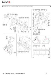
9. IMPLEMENT CARRIER FRAME MODELS<br />
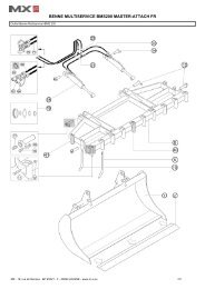
9.1 <strong>MX</strong> Master-Attach implement carrier frame<br />
9.2 Euro implement carrier frame<br />
9.3 <strong>MX</strong> Master-Attach / Euro implement carrier frame<br />
To switch from the <strong>MX</strong> Master-Attach 1 position to the<br />
Euro position 2 ,<br />
— Remove the pins,<br />
— Tilt the hitch shoes downwards,<br />
— Ensure that the hitch shoes are kept in position by the<br />
spring rods,<br />
— Put the pins back to their initial position.<br />
• 19, rue de Rennes • BP 83221 • F - 35690 ACIGNÉ<br />
18 Modifi cation reserved
9.4 Euro / SMS / ALÖ3 implement carrier frame<br />
To switch from the SMS 1 or ALÖ3 2 position to the<br />
Euro 3 position,<br />
Remove the split pins then the pins,<br />
— Take the RH hitch shoe, and position it on the left by<br />
rotating it through 180°,<br />
— Proceed in the same manner for the LH hitch shoe.<br />
9.5 <strong>MX</strong> Master-Attach / Faucheux-Blanc implement carrier<br />
frame<br />
To switch from the <strong>MX</strong> Master-Attach position 1 to the<br />
Faucheux-Blanc position 2 ,<br />
— Remove the hitch shoes from their storage position,<br />
— Fit them in the hitching position and add the 4 attachment<br />
pins,<br />
— Fit the lynch pins to the attachment pins.<br />
10. IMPLEMENT LEVEL INDICATOR<br />
The implement level indicator is useful for implement repositioning. Effi cient even while lowering the loader, it is adjustable<br />
depending on the implement type.<br />
Implement in position<br />
• 19, rue de Rennes • BP 83221 • F - 35690 ACIGNÉ<br />
Indicator<br />
19 Modifi cation reserved
11. SELF LEVELLING, PCH System *<br />
The hydraulic compensating parallelogram system operates automatically.<br />
The system is equipped with safety hydraulic componants that should not be modifi ed under any circumstances.<br />
11.1 "Bucket" Position<br />
When the loader is being raised or lowered, the PCH system<br />
keeps the implement in the best suited position. i.e. the loaded<br />
material does not fall forwards or backwards.<br />
11.2 "Pallet" Position<br />
When the loader is being raised or lowered, the PCH system<br />
maintains the pallet carrier in a horizontal position. i.e. the<br />
material loaded level at ground level is maintained in the<br />
horizontal position while lifting.<br />
12. SHOCK ELIMINATOR SYSTEM *<br />
Shocks are eliminated when moving the loader or<br />
when it stops suddenly when being lowered.<br />
This system softens jolting on the tractor and therefore<br />
jarring in the cab.<br />
The Shock Eliminator can be enabled or disabled<br />
directly from the cab (electric isolation option).<br />
* depending on equipment<br />
• 19, rue de Rennes • BP 83221 • F - 35690 ACIGNÉ<br />
Without<br />
SHOCK ELIMINATOR<br />
With<br />
SHOCK ELIMINATOR<br />
20 Modifi cation reserved
13. CROWD SYSTEM SPEED RESTRICTOR *<br />
The crowd speed restrictor is located at the bottom of the 3rd service solenoid valve, inside the R/H loader arm. See diagram.<br />
13.1 ON / OFF :<br />
ON : restrictor is activated, Crowd system has low speed.<br />
OFF : restrictor is not activated. Crowd system operates<br />
normal speed.<br />
13.2 Adjustment<br />
— Place lever in position "ON",<br />
— Un-tighten nut A.<br />
— Adjust crowd system speed with screw B.<br />
— Re-tighten nut A.<br />
— Check speed after adjustment.<br />
14. ACS *<br />
The automatic upgrade of the ACS tool (option) is available for loaders<br />
that are controlled by the original control valve of the tractor or the <strong>MX</strong><br />
"Flexpilot" or "Techpilot" control valves.<br />
14.1 Adjustment of implement position.<br />
The setting of the implement positon is made with the implement<br />
level indicator rod. See diagram.<br />
— Place implement in position,<br />
— Lay implement down on the ground,<br />
— Unscrew the screw, fi gure A,<br />
— Place rod end in front of the sensor, fi gure B,<br />
— Tighten screw again, fi gure A.<br />
14.2 Automatic implement position return<br />
With Flexpilot:<br />
ACS only crowds the implement.<br />
Implement in dumped position, press and hold the black button<br />
of the joystick: implement stops automatically when preset<br />
position is reached.<br />
With Techpilot:<br />
ACS works both ways: crowding and dumping. If implement<br />
stays in dumped position, loader will crowd.<br />
If implement stays in crowded position, loader will dump.<br />
Press and hold the black button on the joystick: implement stops<br />
automatically when preset position is reached.<br />
* depending on equipment<br />
• 19, rue de Rennes • BP 83221 • F - 35690 ACIGNÉ<br />
A<br />
21 Modifi cation reserved<br />
B
15. SCS *<br />
Synchronisation bucket/grab (option) works both ways:<br />
— Grab opening / bucket dumping<br />
— Bucket crowding / grab closing<br />
SCS works only when loader has 3 rd service.<br />
15.1 SCS ON / OFF<br />
An ON/OFF switch is located on the MACH SYSTEM. An LED<br />
indicates to the driver in his cab if SCS is ON or OFF.<br />
— LED ON : SCS in service.<br />
— LED OFF : SCS OFF.<br />
15.1.1 Loader with Speed Link<br />
A system located inside the SCS compatable Speed Link plug on<br />
the implement will make the automatic activation of the system<br />
when connecting the implement.<br />
Note:<br />
The switch located on Mach System indicates if the SCS is ON or<br />
OFF depending on the implement specifi cation (SCS compatible<br />
or not).<br />
If it is required to disconnect SCS when using SCS compatable<br />
implement, please turn off switch.<br />
15.2 SCS driving<br />
SCS is opperated through the same button as 4th function and<br />
crowding or dumping.<br />
— Grab opening / bucket dumping : press 4th function button +<br />
dumping<br />
— Bucket crowding / grab closing : press 4th function button +<br />
crowding<br />
Remarks :<br />
— In order to optimise the SCS when loading a trailer, it is recommanded<br />
to start the system when the implement arrives at the level position.<br />
— If grab is fully opened before bucket fully is dumped, release 4th function switch to continue dumping.<br />
— If bucket is totally dumped before grab is fully opened, use 3rd service<br />
to open the grab.<br />
* depending on equipment<br />
• 19, rue de Rennes • BP 83221 • F - 35690 ACIGNÉ<br />
LED<br />
ON / OFF<br />
MACH System Clutch<br />
SHUNT<br />
22 Modifi cation reserved
16. SAFETY DEVICE ON LIFTING/CROWDING *<br />
If the loaders lifting operation requires people to be in the close proximity, the hydraulic circuit of the loader must have safety<br />
device fi tted to it.<br />
This in accordance with the standard EN 12525/A1, from July 2006<br />
* depending on equipment<br />
17. MAINTENANCE<br />
Caution<br />
Change the tractor hydraulic oil and fi lters regularly in accordance with the tractor<br />
manufacturer recommendations. Used oil does not lubricate, it also contributes to the damage<br />
of all hydraulic components (pump, valves, rams…).Even clear oil may not lubricate.<br />
For any maintenance operations made whilst the loader is the raised position, the loader must be locked into position.<br />
Two possibilities :<br />
— Lock the joystick in the cab (see chapter 19, Control).<br />
or,<br />
— Disconnection of the MACH System if loader has one, or closing the tap fi tted on the lifting coupler if the loader is<br />
without MACH System (see chapter 5, Loader unhitching).<br />
When using a high presssure cleaner, do not direct water towards the<br />
electrical components.<br />
Clean the implement and the loader front after each use. The acid from<br />
slurry, fertilisers and silage is harmful to paint, steel and the machine’s<br />
pivot points.<br />
Grease every 10 hours and after each wash (grease eliminates water)<br />
and particularly after washing with a high pressure cleaner.<br />
Check the following each month, and more frequently when used<br />
intensively:<br />
— Condition of the loader articulations. If necessary, replace the wear bushes and/or the pins.<br />
— The wear bushes must be replaced if they are less than 1 mm thick.<br />
— The tractor’s hydraulic oil level and the sealing of the hydraulic system. If you notice any internal or external leaks on the<br />
hydraulic parts (rams, hoses, connectors, Mach, couplings, etc.), contact your dealer.<br />
— Condition of the hoses: replace them if you notice any small cracks or oil seepage.<br />
— Correct operation of the monolever (cables, play, locking, etc.).<br />
— Condition of the electric wiring. Please contact your dealer if there is any damage to connectors or cables.<br />
— Mechanical condition (any cracking, deformation, fretting on stops, play, parking stands, etc.). Please contact your dealer<br />
if there is any abnormal wear.<br />
• 19, rue de Rennes • BP 83221 • F - 35690 ACIGNÉ<br />
23 Modifi cation reserved
Check the tightness of the bracket after 10, 50 hours then every 100 hours or when carring out tractor maintenance. In case of<br />
untightness, please contact your dealer.<br />
IMPORTANT:<br />
All the screws needing to be retightened must be inspected, changed if necessary, cleaned and smeared with loctite.<br />
Tighten the screws to the tightening torque specifi ed in the table below.<br />
Use of a pneumatic spanner to tighten the screws on the tractor is forbidden.<br />
Tightening torque (Nm)<br />
Thread<br />
8.8<br />
Class of bolt<br />
10.9 12.9<br />
M 8 21 29 35<br />
M 10 42 58 70<br />
M 12 72 101 121<br />
M 14 114 160 193<br />
M 16 174 245 295<br />
M 18 240 340 405<br />
M 20 340 475 570<br />
M 22 455 640 765<br />
M 30 x 150 500<br />
M 40 x 150 500<br />
18. GENERAL INFORMATION<br />
— Each implement is designed for a specifi c use and has its own resistance limits.<br />
— Land clearing and stump extraction are forbiden. Such work should be carried out by a specialist vehicle and is not possible<br />
for an agricultural loader.<br />
— Use the tractor’s power to enter in the material to be moved rather than approaching it with speed, which will generate high<br />
stress on tractor and loader.<br />
— When the load to be manoeuvred is too heavy, do not apply force to the hydraulic components. This also applies when rams<br />
are fully closed or extended. Please release the control lever.<br />
— When ground levelling, work at a slow speed with the<br />
implement at a maximum angle of 50° with respect to the<br />
ground.<br />
Operate with fl exibility and in a judicious manner.<br />
• 19, rue de Rennes • BP 83221 • F - 35690 ACIGNÉ<br />
50˚ max<br />
24 Modifi cation reserved
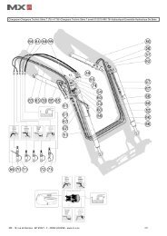
19. CONTROL<br />
Important: Never leave the tractor with loader in raised position.<br />
All spool valves produce an internal leak required for correct operation.<br />
19.1 On tractor valves :<br />
Please report to the tractor’s instruction book.<br />
19.1.1 Front/rear control selector (option) :<br />
From the original joystick of the tractor, the operator can control<br />
the <strong>MX</strong> loader or the rear couplers from the cab.<br />
19.2 On <strong>MX</strong> valves :<br />
19.2.1 Security<br />
Involuntary loader manoeuvre can be avoided. The <strong>MX</strong> joystick<br />
can be locked.<br />
See diagram.<br />
19.2.2 Lifting-crowding movements<br />
• 19, rue de Rennes • BP 83221 • F - 35690 ACIGNÉ<br />
Front/rear control selector (option)<br />
PROPILOT FLEXPILOT TECHPILOT<br />
25 Modifi cation reserved
19.2.3 Other movements<br />
PROPILOT - FLEXPILOT<br />
3rd function :<br />
Green button + Crowding.<br />
4th function - SCS :<br />
Blue button + Crowding.<br />
ACS : Implement return to dig (Flexpilot only)<br />
Black button.<br />
FAST-LOCK :<br />
Implement hydraulic locking / unlocking<br />
Green + Orange buttons + Crowding.<br />
SPEED-LINK :<br />
Implement automatic locking / unlocking including hydraulic and electric connections.<br />
Green + Orange buttons + Crowding.<br />
TECHPILOT<br />
Please refer to Techpilot instruction book.<br />
• 19, rue de Rennes • BP 83221 • F - 35690 ACIGNÉ<br />
26 Modifi cation reserved
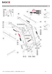
20. TECHNICAL SPECIFICATIONS<br />
• 19, rue de Rennes • BP 83221 • F - 35690 ACIGNÉ<br />
<strong>MX</strong> T6 <strong>MX</strong> T8 <strong>MX</strong> T10 <strong>MX</strong> T12 <strong>MX</strong> T15 <strong>MX</strong> T16<br />
Length (A) 2.30 m 2.40 m 2.50 m 2.60 m 2.75 m 2.75 m<br />
Width (B) 1.18 m 1.18 m 1.18 m 1.18 m 1.18 m 1.38 m<br />
Height (C) 1.72 m 1.78 m 1.83 m 1.87 m 2.05 m 2.05 m<br />
Minimum weight (Without option) 460 Kg 480 Kg 535 Kg 550 Kg 660 Kg 697 Kg<br />
Maximum weight (With option) 505 Kg 560 Kg 615 Kg 635 Kg 807 Kg 844 Kg<br />
Maximum height at implement pivot * 3.75 / 3.60 m 3.85 m 4.00 m 4.15 m 4.60 m 4.60 m<br />
Maximum height under horizontal bucket (1) # 3.50 / 3.35 m 3.60 m 3.75 m 3.90 m 4.35 m 4.35 m<br />
Maximum height under dumped bucket (2) # 2.95 / 2.80 m 3.05 m 3.20 m 3.35 m 3.80 m 3.80 m<br />
Digging depth (3) # 0.20 m 0.20 m 0.20 m 0.20 m 0.20 m 0.20 m<br />
Dumping angle at maximum height (4) # 52° 55° 55° 55° 50° 50°<br />
Crowd angle (5) # 47° 52° 52° 52° 51° 51°<br />
Lift force at implement pivot * (Kg) 1600 Kg 2100 Kg 2400 Kg 2720 Kg 3000 Kg 3000 Kg<br />
Lift capacity at implement pivot over the entire lifting range * (Kg)<br />
Payload on pallet 0.60 m in front of the forks<br />
1250 Kg 1890 Kg 2190 Kg 2490 Kg 2670 Kg 2670 Kg<br />
At ground level (Kg) Sans PCH 1030 / 1150 Kg 1350 Kg 1580 Kg 1770 Kg 1930 Kg 1930 Kg<br />
Avec PCH 1360 / 1450 Kg 1800 Kg 2080 Kg 2360 Kg 2660 Kg 2660 Kg<br />
At 2 m height (Kg) Sans PCH 930 / 1000 Kg 1300 Kg 1540 Kg 1750 Kg 1890 Kg 1890 Kg<br />
Avec PCH 1180 / 1300 Kg 1720 Kg 2000 Kg 2250 Kg 2560 Kg 2560 Kg<br />
At 3 m height (Kg) Sans PCH 800 / 900 Kg 1200 Kg 1470 Kg 1690 Kg 1850 Kg 1850 Kg<br />
Avec PCH 1130 / 1220 Kg 1630 Kg 1980 Kg 2230 Kg 2460 Kg 2460 Kg<br />
At maximum height ( Kg) Sans PCH 780 / 860 Kg 1120 Kg 1450 Kg 1570 Kg 1750 Kg 1750 Kg<br />
Avec PCH 1100 / 1200 Kg 1610 Kg 1960 Kg 2200 Kg 2350 Kg 2350 Kg<br />
Lifting time (s) 3.9 sec 4.6 sec 5.4 sec 6.2 sec 8.2 sec 8.2 sec<br />
Dumping time (s) 1 sec 1 sec 1 sec 1.4 sec 1.4 sec 1.4 sec<br />
Specifi cations measured at 190 bar and a fl ow rate of 60 l/min. Data varies depending on the type of tractor used.<br />
# Indicated data are with a loose material bucket.<br />
* Values at ground level and at implement pivot are not considered to be working data.<br />
27 Modifi cation reserved<br />
4<br />
5<br />
2 1<br />
3
DECLARATION OF CONFORMITY<br />
We, the manufacturers :<br />
<strong>MX</strong><br />
19,Rue de Rennes<br />
F - 35690 Acigné<br />
Declare that the products:<br />
<strong>MX</strong> T6, <strong>MX</strong> T8, <strong>MX</strong> T10, <strong>MX</strong> T12, <strong>MX</strong> T15 and <strong>MX</strong> T16 loaders<br />
Comply with standard EN 12525, and its amendments A1 and A2, which presupposes<br />
compliance with the requirements of directive 2006/42 EC of the European Parliament<br />
and of the Council of 17 May 2006 on machinery.<br />
Acigné, the 30th of March 2011<br />
Loïc Mailleux<br />
Technical Manager
19, rue de Rennes<br />
BP 83221<br />
F - 35690 ACIGNE<br />
Tél. : +33 (0)2 99 62 52 60<br />
Fax : +33 (0)2 99 62 50 22<br />
e-mail : contact@m-x.eu