305 Datalogger
305 Datalogger
305 Datalogger

You also want an ePaper? Increase the reach of your titles
YUMPU automatically turns print PDFs into web optimized ePapers that Google loves.
RS-232<br />
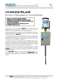
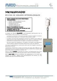
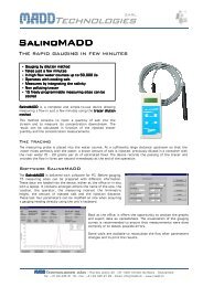
<strong>305</strong> <strong>Datalogger</strong><br />
RANGE -200°C<br />
-328°F<br />
POWER-UP OPTIONS<br />
REC<br />
SETUP<br />
REL HOLD<br />
CLOCK<br />
REC<br />
INTV<br />
°C/°F<br />
1370°C<br />
2498°F
CONTENTS<br />
TITLE PAGE<br />
I. Introduction…………………………………………………………………………….…..1<br />
II. Specifications…………………………………………………………………………… 1<br />
III. Symbol Definition and Button Location………………………………. 2<br />
IV. Operation Instructions…………………………………………….……………… 3<br />
4.1 Power-Up…………………………………………………………………………………....3<br />
4.2 Connection the Thermocouples………………………………………………………...3<br />
4.3 Selecting the Temperature Scale………………………………………………………. 3<br />
4.4 Data-Hold Operation……………………………………………………………………… 3<br />
4.5 DataLogger………………………………………………………………………………… 3<br />
4.6 Clock Setup ……………………………………………………………………………….. 3<br />
4.7 Recording Interval Setup……..…………………………………………………………. 4<br />
4.8 Relative Operation……………………………………………………………………….. 4<br />
4.9 MAX/MIN Operation………………………………………………………………………. 4<br />
4.10 Auto Power Off……………………………………………………………………………4<br />
4.11 Low Battery Condition …………………………………………………………………. 4<br />
4.12 Calibration Point………………………………………………………………………… 4<br />
4.13 Digital Output…………………………………………………………………………….. 5<br />
V. Setup ThermoLog (Thermo DataLogger)—RS232 interface<br />
software……………………………………………………………………………………… 7
I. Introduction:<br />
1<br />
Data Logger Instruction Manual<br />
This instrument is a digital thermometer for use with any K-type thermocouple as temperature<br />
sensor. Temperature indication follows National Bureau of Standards and IEC584<br />
temperature/voltage table for K-type thermocouples. Its internal memory can keep up to 16241<br />
records.(note1.) It uses RS232 interface to perform bi-directional communication with PC.<br />
II. Specifications:<br />
Numerical Display: 4 digital Liquid Crystal Display<br />
Measurement Range: -200°C ~ 1370°C -328°F ~ 2498°F<br />
Resolution: -200°C~ 200°C 0.1°C; 200°C ~1370°C 1°C<br />
-200°F~ 200°F 0.1°F; else 1°F<br />
Input Portection at Thermocouple Input: 60V DC, or 24Vrms AC<br />
Environmental:<br />
� Operating Temperature and Humidity: 0°C ~50°C (32°F ~ 122°F) ; 0 ~ 80% RH<br />
� Storage Temperature and Humidity: -10°C to 60°C (14°F ~ 140°F); 0 ~ 80% RH<br />
� Altitude up to 2000 meters.<br />
Accuracy: at ( 23 ± 5°C )<br />
Range Accuracy<br />
Temperature Coefficient:<br />
-200°C ~ 200°C ±(0.2% reading + 1°C) For ambient temperatures from 0°C ~ 18°C and 28°C<br />
200°C ~ 400°C ±(0.5% reading + 1°C) ~ 50°C, for each °C ambient below 18°C or above<br />
400°C~1370°C ±(0.2% reading + 1°C) 28°C add the following tolerance into the accuracy<br />
spec.<br />
-328°F ~ -200°F ±(0.5% reading + 2°F)<br />
0.01% of reading + 0.03°C<br />
-200°F ~ 200°F ±(0.2% reading + 2°F)<br />
( 0.01% of reading + 0.06°F )<br />
200°F ~ 2498°F ±(0.3% reading + 2°F)<br />
Note:<br />
The basic accuracy Specification does not include the error of the probe. Please refer to the<br />
probe accuracy specification for additional details.<br />
Sample Rate: 2.5 times per second<br />
Dimension: 184×64×30mm<br />
Weight: 210g Approx.<br />
Accessory: K Type Bead Probe, Battery, Carrying Case, Instruction Menu, Soft Ware Package<br />
(Program, RS232 Connection Cable)<br />
Power requirement: 9 Volt Battery, NEDA 1604 or JIS 006P or IEC6F22<br />
Battery Life: Approx. 100hrs with alkaline battery<br />
AC Adapter: 9VDC ±15% 100mA<br />
Plug Diameter: 3.5mm×1.35mm<br />
Option : AC Adapter<br />
note1:<br />
Every time you press "REC" button to start recording data and press "REC" button again to stop<br />
recording, there will be a data set in memory, you can store as many data sets as you want until memory<br />
is full.
III. Symbol Definition and Button Location:<br />
: This indicates that the minus temperature is sensed.<br />
℃℉ : Centigrade and Fahrenheit indication.<br />
△REL : The reading is now under Relative Mode.<br />
K : Thermocouple Type Indication<br />
MAX : The Maximum value is now being displayed<br />
MIN : The Minimum value is now being displayed<br />
: This indicates auto power off is enabled.<br />
: This indicates that the display data is being held.<br />
m-d : month and day<br />
h:m : hour and minute<br />
m:s : minute and second<br />
y : year<br />
2<br />
Data Logger Instruction Manual<br />
: The Battery is not sufficient for proper operation.<br />
REC : This indicates that the tester is recording. If it blinks, it indicates the memory is full.<br />
2<br />
3<br />
SETUP<br />
4 7<br />
5<br />
CLOCK INTV<br />
RANGE: 200 C 1370 C<br />
328 F 2498 F<br />
POWER-UP OPTIONS<br />
REC<br />
60V<br />
24V<br />
MAX<br />
REL<br />
HOLD<br />
REC C F<br />
1<br />
6<br />
8<br />
CAL<br />
DC9V<br />
OUTPUT<br />
9<br />
9V BATTERY<br />
NEDA 1604 6F22 006P<br />
PLEASE READ<br />
MANUAL FOR SAFETY<br />
OPEN<br />
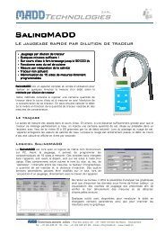
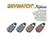
Button Location:<br />
� K type temperature sensor input<br />
connector<br />
� LCD display<br />
� ON/OFF button<br />
� Relative readout button<br />
� Record button<br />
� MAX MIN function control button<br />
� HOLD button<br />
� °C, °F control button<br />
� Offset calibration screw<br />
� Digital output connector<br />
11 AC power adapter connector<br />
12 Tripod connector<br />
13 Battery cabinet cover
IV. Operation Instructions:<br />
3<br />
Data Logger Instruction Manual<br />
4.1 Power-Up<br />
Press the power button to turn the thermometer ON or OFF.<br />
When the user power it on, the LCD will show how much memory<br />
space is available to use.<br />
For example: It indicates that there are 16,000 records memory space available.<br />
4.2 Connection the Thermocouples<br />
For measurement, plug the thermocouple into the input connectors.<br />
4.3 Selecting the Temperature Scale<br />
When the meter was first power on, the default scale setting is set at Celsius (°C) scale. The user<br />
may change it to Fahrenheit (°F) by pressing “ °C/°F ” button and vice versa to Celsius. Next time<br />
you power on, the scale setting will be the same as which when you powerd off last time.<br />
4.4 Data-Hold Operation<br />
The user may hold the present reading and keep it on the display by pressing the “HOLD” button.<br />
When the held data is no longer needed, one may release the data-hold operation by pressing<br />
“HOLD” button again.<br />
When the meter is under Data Hold operation, the “△REL”, "max min" and “ °C/°F ” button are<br />
disabled. (when you press "△REL” ,“ °C/°F ” and "max min" button in HOLD mode, there will be<br />
two continuous beeps)<br />
To exit the MAX/MIN mode, one may press and hold "MAX MIN" button for two seconds.<br />
4.5 DataLogger:<br />
When one press the "REC" button, the meter will start recording,<br />
press the "REC" button again will stop recording, If you want to<br />
clear the memory, power off the meter, then press and hold “REC”<br />
button and then press power button and hold at least 2 seconds,<br />
then release all buttons ,then LCD will show "CLR" to clear the<br />
memory.<br />
4.6 Clock Setup :<br />
1: press and hold “MAX MIN” button and then power on the meter:<br />
2: press “△REL”(clock):<br />
3: press "REC" ▲ or "°C/°F" ▼ to increase or decrease number,<br />
press “△REL”(clock) to adjust next item. The adjusting order is<br />
year→month→day→hour→minute, then press “△REL” (clock)<br />
to finish adjusting. If you want abort during a setup process, press<br />
power button to cancel.
4.7 Recording Interval Setup :<br />
4<br />
Data Logger Instruction Manual<br />
1: press and hold “MAX MIN” button and then power on the meter:<br />
2: press “HOLD"(INTV)<br />
3: press "REC" ▲ or "°C/°F" ▼ to increase or decrease number,<br />
press “HOLD" (INTV) to adjust next item, then press “HOLD” (INTV)<br />
to finish. If you want abort during a setup process, press power<br />
button to cancel.<br />
4.8 Relative Operation:<br />
When one press the “△REL” button, the meter will memorize the present reading and the difference<br />
between the new reading and the memorized data will be shown on the display. Press the “△REL”<br />
button again to exit the Relative operation. When the meter is under relative operation, “ °C/°F ”<br />
button is disabled. (when you press “ °C/°F ” button in relative mode, there will be two continuous<br />
beep)<br />
4.9 MAX/MIN Operation:<br />
When one press the "MAX MIN" button the meter will enter the MAX/MIN mode. Under this mode<br />
the maximum value, minimum value is kept in the memory simultaneously and updated with every<br />
new data.<br />
When the MAX symbol is display, the Maximum is shown on the display.<br />
Press "MAX MIN" again, then the MIN symbol is on the display and also the minimum reading.<br />
Press "MAX MIN" again, MAX, and MIN will blink together. This means that all these data is<br />
updated in the memory and the reading is the present temperature.<br />
One may press "MAX MIN" to circulate the display mode among these options.<br />
When the meter is under "MAX MIN" operation, “△REL” and “ °C/°F ” button are disabled.(when<br />
you press "△REL” and “ °C/°F ” button in "MAX MIN" mode, there will be two continuous beep)<br />
To exit the MAX/MIN mode, one may press and hold "MAX MIN" for two seconds.<br />
4.10 Auto Power Off:<br />
By default, when the meter is powered on, it is under auto power off mode. The meter will power<br />
itself off after 30 minutes if no key operation and no RS232 communication and no recording.<br />
combination at power on can disable auto power off.<br />
One may press and hold “HOLD” button and then power on the meter and there will be two<br />
successive beeps to indicate that auto power off is disabled and the will not show up.<br />
4.11 Low Battery Condition<br />
When the battery voltage is under proper operation requirement, the symbol will show on the<br />
LCD and the battery need to be replaced with new one.<br />
4.12 Calibration Point:<br />
input Adjust VR tolerance<br />
0 °C VR1 ± 0.1 °C<br />
190 °C VR2 ± 0.1 °C<br />
1000 °C VR3 ± 1 °C<br />
1900 °F VR4 ± 1 °F<br />
P.S<br />
Normally, performing offset Calibration with thermal<br />
stabled ice water through VR1 will give a very good<br />
calibration result.
4.13 Digital Output:<br />
The Digital Output is a 9600bps N 81 serial interface.<br />
The RX is a 5V normal high input port.<br />
The TX is a 5V normal high output port.<br />
5<br />
TX RX GND<br />
Data Logger Instruction Manual<br />
The command of Digital Output is list below:<br />
RS232 command Function Remarks<br />
K(ASC 4BH) Ask for model No. Return 4 bytes<br />
A(ASC 41H) Inquire all encoded data Return encoded 10 byte<br />
H(ASC 48H) Hold button<br />
M(ASC 4DH) MAX/MIN button<br />
N(ASC 4EH) Exit MAX/MIN mode<br />
R(ASC 52H) REL button<br />
C(ASC 43H) C/F button<br />
U(ASC 55H) Dump all memory of thermometer return 32768 bytes<br />
P(ASC 50H) Load recorded data<br />
•Command K:<br />
Return 4 bytes. For example, when sends command "K" to meter, it will return "3","0","5",<br />
ASCII(13) .<br />
•Command U:<br />
Return 32768 bytes .<br />
•Command P:<br />
Instead of returning all 32768 bytes, it only return recorded data .<br />
•Command H:<br />
Equivalent to one pushing on the HOLD button and no message is returned.<br />
•Command M:<br />
Equivalent to one pushing on the MAX/MIN button and no message is returned.<br />
•Command N:<br />
Equivalent to one pushing and hold the MAX/MIN button for two seconds to exit MAX/MIN mode.<br />
•Command R:<br />
Equivalent to one pushing on the REL button and no message is returned.<br />
•Command C:<br />
Equivalent to one pushing on the °C/°F button and no message is returned.<br />
•Command A:<br />
1 nd BYTE:<br />
The first byte is the start byte , it value is 2.<br />
2 nd BYTE:<br />
bit7 bit6 bit5 bit4 bit3 bit2 bit1 bit0<br />
C/F Low Bat Hold REL MAX/MIN REC<br />
bit 0: 1→recording mode, 0→not recording<br />
bit 2 bit 1<br />
0 0 →normal mode<br />
0 1 →MAXIMUN mode<br />
1 0 →MINIMUN mode<br />
1 1 →calculate MAX/MIN in background mode .
6<br />
Data Logger Instruction Manual<br />
bit3: no use.<br />
bit4: 1→REL<br />
bit5: 1→ HOLD, 0→not HOLD<br />
bit6: 1→LOW BATTERY , 0→BATTERY NORMAL<br />
bit7: 1→°C 0→°F<br />
3 th BYTE:<br />
bit7 bit6 bit5 bit4 bit3 bit2 bit1 bit0<br />
Auto Power Off Memory full resolution sign OL<br />
bit0: 1→main window value is OL, 0→not OL<br />
bit1: 1→main window value is minus, 0→main window value is plus.<br />
bit2: 1→4 th byte and 5 th byte represent #### , 0→4 th byte and 5 th byte represent ###.#<br />
bit6: 1→Memory is full. 0→Memory is not full.<br />
bit7: 1→Auto power off enabled. 0→Auto power off disabled.<br />
4 th BYTE:<br />
first two BCD code of main window value.<br />
5 th BYTE:<br />
last two BCD code of main window value<br />
6 th BYTE:<br />
BCD code of month.<br />
7 th BYTE:<br />
BCD code of day.<br />
8 th BYTE:<br />
BCD code of hours.<br />
9 th BYTE:<br />
BCD code of minute.<br />
10 th BYTE: end byte, it value is 3, 1 nd and 10 th are used to check frame error.<br />
Appendix: Thermo couple probe specification<br />
Model Range Tolerances Description<br />
TP-K01<br />
Bead probe<br />
-50℃ to 200℃<br />
-58℉ to 392℉<br />
±2.2℃ or ±0.75%<br />
(±3.6℉ or ±0.75%)<br />
TP-K01:<br />
probe for general condition measurements, especially for<br />
complex and hard to reach places.<br />
with Teflon tape insulation Maximum<br />
insulating temperature : 260℃
7<br />
Data Logger Instruction Manual<br />
V. Setup ThermoLog (Thermo DataLogger)—RS232 interface software:<br />
� The ThermoLog package contains:<br />
1.Two 3.5” diskettes<br />
2.Custom designed RS232 cable for THERMOLOG.<br />
� System Required:<br />
Windows 95 or Windows 98 or Windows NT 4.0 above.<br />
� Minimum Hardware Required:<br />
486-100 MHz PC compatible , 16 MB RAM ;<br />
At least 5 MB hard disk space available to install THERMOLOG program. Recommended<br />
display resolution is 800X600.<br />
� Install ThermoLog:<br />
1.We recommend close all other application before installing ThermoLog.<br />
2.Insert setup diskette 1 to floppy disk drive.<br />
3.Choose the Start button on the Taskbar and select Run.<br />
4.Type A:\SETUP and choose OK, then it will copy ThermoLogg.exe ( executable file ) and help<br />
file to your hard disk ( default is c:\program files\ThermoLog ).<br />
For other operation instruction, please refer to the on-line help while executing ThermoLog.<br />
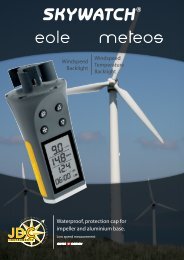
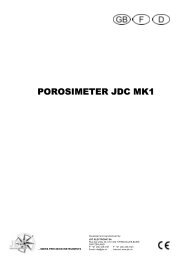
Main Menu<br />
click to show the<br />
presentgraph window<br />
click to show graph ,<br />
panel and tabular<br />
window.<br />
click to show panel<br />
window<br />
click to test if there is any<br />
thermometer connected to PC<br />
click to exit ThermoLog<br />
click to show on-line help<br />
click to load the recorded data form<br />
thermometer<br />
click to show the present list data<br />
it shows whether thermometer is<br />
connected or not<br />
Link Test :<br />
Open Link Test window to search for thermometer connected to PC. When you start the<br />
THERMOLINK, this window will display first and search for thermometer. The result will be<br />
shown in the text box.
8<br />
Data Logger Instruction Manual<br />
Control Panel:<br />
By opening the Control Panel Window, the user can control thermometer via the button in this<br />
window.<br />
DataLogger:<br />
By opening the DataLogger Window, the user can load the recorded data from themometer.<br />
Tabular:<br />
By opening the Tabular window, the present data from the thermometer will be listed in a<br />
scrolling table. These data can be stored as a file or the table can be copy to other software<br />
such as EXCEL for further analysis.<br />
Graph:<br />
Open Real-Time Graph window to show the present data in graph.<br />
Exit:<br />
Terminates THERMOLOG program.<br />
Tray Icon:<br />
When THERMOLOG is running , there will be an icon displayed on the Windows Tray area<br />
(see figure below), you can click this icon then it will show a pop-up menu.<br />
Tray Icon