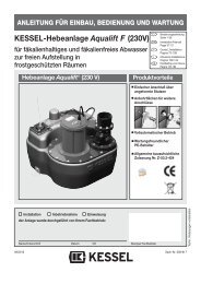
KESSEL - Hebeanlage - Minilift für fäkalienfreies Abwasser zur Über ...
KESSEL - Hebeanlage - Minilift für fäkalienfreies Abwasser zur Über ...
KESSEL - Hebeanlage - Minilift für fäkalienfreies Abwasser zur Über ...

Create successful ePaper yourself
Turn your PDF publications into a flip-book with our unique Google optimized e-Paper software.
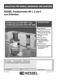
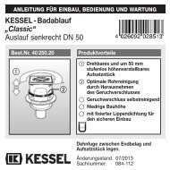
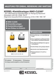
ANLEITUNG FÜR EINBAU, BEDIENUNG UND WARTUNG<br />
<strong>KESSEL</strong> - <strong>Hebeanlage</strong> - <strong>Minilift</strong><br />
<strong>für</strong> <strong>fäkalienfreies</strong> <strong>Abwasser</strong> <strong>zur</strong> <strong>Über</strong>- oder Unterflurinstallation<br />
Abb. 28 560<br />
Abb. 28 570<br />
Installation Inbetriebnahme Einweisung<br />
der Anlage wurde durchgeführt von Ihrem Fachbetrieb:<br />
Best. Nr. 28 560 / 28 570<br />
Produktvorteile<br />
Name/Unterschrift Datum Ort Stempel Fachbetrieb<br />
Kompakte Bauweise<br />
Förderhöhe bis 6,5 m<br />
Einhand-Schnellverschluß<br />
<strong>zur</strong> mobilen Verwendung der Pumpe<br />
LGA<br />
Landesgewerbeamt Bayern<br />
Bauart<br />
gepr geprüft ft<br />
und und überwacht berwacht<br />
mit Sicherheit<br />
geprüfte Qualität<br />
Seite 1-12<br />
Page 13-24<br />
Zulassungsnummer: Z-53.3-387<br />
Änderungsstand: 06/2011<br />
Sachnummer: 157-030<br />
Techn. Änderungen vorbehalten
Inhaltsverzeichnis<br />
1. Allgemein 1.1 Verwendung...................................................................................... Seite 3<br />
1.2 Anlagenbeschreibung ....................................................................... Seite 3<br />
1.2.1 <strong>Über</strong>flurinstallation ............................................................................ Seite 3<br />
1.2.2 Unterflurinstallation ........................................................................... Seite 3<br />
2. Einsatzbereiche 2.1 Dauerhafter Einbau........................................................................... Seite 4<br />
2.2 Mobiler Einsatz der Pumpe............................................................... Seite 4<br />
3. Einbau 3.1 Einbau in die Bodenplatte/Unterflurinstallation ................................. Seite 5/6<br />
3.2 Freie Aufstellung/<strong>Über</strong>flurinstallation ................................................ Seite 7/8<br />
3.3 Hinweis ............................................................................................. Seite 9<br />
4. Inbetriebnahme 4.1 Anlagen - Daten................................................................................ Seite 10<br />
4.2 Hinweis ............................................................................................. Seite 11<br />
5. Inspektion und Wartung 5.1 Inspektion ......................................................................................... Seite 11<br />
5.2 Wartung ............................................................................................ Seite 11<br />
6. Gewährleistung .......................................................................................................... Seite 11<br />
2
1.1 Verwendung<br />
Fäkalienfreies Schmutzwasser, entsprechend<br />
DIN EN 12056, das unterhalb der<br />
Rückstauebene anfällt und kontinuierlich<br />
abgeleitet werden soll, ist über eine <strong>Abwasser</strong>hebeanlage<br />
zu entsorgen.<br />
Dies gilt auch <strong>für</strong> Abwässer die unterhalb<br />
der Kanal-Anschlusshöhe anfallen.<br />
1.2 Anlagenbeschreibung<br />
1.2.1 <strong>Über</strong>flurinstallation<br />
Durch die geruchs- und wasserdichte Abdeckung<br />
kann der Kunststoffbehälter frei<br />
aufgestellt werden.<br />
Die Belüftung der Anlage erfolgt dabei über<br />
einen Aktiv-Kohlefilter in der Anlagenabdeckung.<br />
Dadurch werden Geruchsbelästigungen<br />
im Aufstellungsraum verhindert.<br />
Eine separate Entlüftungsleitung kann - entsprechend<br />
den Vorschriften - auch bis übers<br />
Dach verlegt werden.<br />
Mit der Kessel-<strong>Hebeanlage</strong>-<strong>Minilift</strong> ® können<br />
auch nachträglich Entwässerungsstellen installiert<br />
werden, wenn in ihere Nähe kein<br />
3<br />
1. Allgemein<br />
<strong>Abwasser</strong>anschluss liegt, z. B. bei Waschtisch-,<br />
Gästezimmer- oder Hotelsanierung<br />
(nachträgliche Nasszelleninstallation).<br />
1.2.2 Unterflurinstallation<br />
Die <strong>KESSEL</strong>-<strong>Hebeanlage</strong> <strong>Minilift</strong> ® besteht<br />
aus einem Grundkörper mit Abdeckplatte<br />
und Schlitzrost.<br />
Die Pumpe kann durch den Einhand-<br />
Schnellverschluss (1) zu Wartungszwecken<br />
oder <strong>für</strong> den mobilen Einsatz einfach entnommen<br />
werden.<br />
Durch die Anbringung von seitlichen Zulaufstutzen/Rohrdurchführungsdichtung<br />
(2)<br />
können an die <strong>Hebeanlage</strong> weitere <strong>Abwasser</strong>leitungen<br />
angeschlossen werden.<br />
Eine separate Entlüftungsleitung ist nur erforderlich,<br />
wenn der Schlitzrost gegen eine<br />
Abdeckplatte ausgetauscht wird.<br />
Mit dem <strong>KESSEL</strong>-Aufsatzstück können stufenlos<br />
beliebige Einbautiefen realisiert werden.
2.1 Dauerhafter Einbau<br />
- Der <strong>KESSEL</strong>-<strong>Hebeanlage</strong> <strong>Minilift</strong> ® darf nur<br />
<strong>fäkalienfreies</strong> <strong>Abwasser</strong> zugeführt werden.<br />
- Komplette Anlage ist aus Kunststoff. Pumpensteuerung<br />
mittels Schwimmerschalter.<br />
- Für den Einsatz handelsüblicher Haushaltswaschmaschinen<br />
geeignet.<br />
- Die Anlage wird mit 5 m Kabel geliefert.<br />
- max. <strong>Abwasser</strong>temperaturen:<br />
50°C bei Dauerbetrieb<br />
2. Einsatzbereiche<br />
75°C kurzzeitig<br />
Grenzwert <strong>zur</strong> Einleitung in das öffentliche<br />
Kanalnetz: max. 35°C<br />
- pH-Wert: mind. 6 - max. 10<br />
- nicht <strong>für</strong> fetthaltiges <strong>Abwasser</strong> geeignet<br />
2.2 Mobiler Einsatz der Pumpe<br />
- Pumpe kann mit Schnellverschluss an der<br />
Druckleitung im Gehäuse gelöst werden und<br />
ist dann mobil verwendbar.<br />
- Bei mobilem Pumpeneinsatz ist keine Rückschlagklappe<br />
vorhanden. Damit wird die<br />
4<br />
Entleerung der Anschlussleitung sichergestellt.<br />
- Es ist zu beachten, dass die Steckerleitung<br />
beim Wiedereinbau durch das Leerrohr gezogen<br />
werden muss.<br />
HINWEIS:<br />
<strong>Abwasser</strong>-Ansaughöhe kann durchAbnahme<br />
des Pumpen-Ansaugkorbes, der mit 3 Klippverschlüssen<br />
an der Pumpe befestigt ist, verringert<br />
werden.<br />
Achtung: Vor Abnahme des Pumpenansaugkorbes<br />
Netzstecker ziehen.<br />
- Vorsicht bei mobilem Einsatz: Eine Benutzung<br />
der Pumpe in Schwimmbecken und<br />
Gartenteichen und deren Schutzbereichen<br />
ist nur zulässig, wenn die Forderungen nach<br />
VDE 0100, § 49d erfüllt sind.<br />
- HINWEIS betreffend ÖVE: Gemäß § 2022.1<br />
müssen Pumpen zum Gebrauch in Schwimmbecken<br />
und Garten mit einer festenAnschlussleitung<br />
ausgestattet über einen Trenntransformator<br />
gespeist werden. Dabei darf die Nennspannung<br />
sekundär nicht überschritten werden.
5<br />
3. Einbau<br />
Einbau und Montage elektrischer Geräte dürfen nur durch eine Elektrofachkraft<br />
erfolgen (Elektrofachkraft im Sinne VDE 0105)<br />
3.1 Einbau in die Bodenplatte/Unterflurinstallation<br />
Lage der Ablaufstellen unterhalb d. öffentl. Kanalisation<br />
Bevor der Grundkörper in die Bodenplatte eingebaut wird, sind folgende Montagearbeiten<br />
zu erledigen:<br />
1. Flachdichtung (8) über Gewindeteil des<br />
Gewindestückes (6) schieben.<br />
2. Gumminippel (9) in das Gewindestück<br />
einstecken.<br />
max. 45°<br />
3. Komplettiertes Gewindestück von innen<br />
durch vorhandene Aussparung schieben.<br />
4. Sechskanntmutter (7) auf Gewindestück<br />
(6) schrauben.<br />
5. Pumpe auf Führungsrippen am Grund<br />
des Grundkörpers (1) setzen. Pumpe in<br />
der Führung zum Gewindestück schieben,<br />
dabei Anschlussstück (4) in den<br />
Gumminippel (9) einführen und mit Verschluß<br />
(5) fixieren.<br />
6. Zur Kabeldurchführung am Gehäuse<br />
muß eine Rohrdurchführungsdichtung<br />
DN 50 (im Lieferumfang enthalten) montiert<br />
werden. Genaue Anleitung siehe Anbringung<br />
von seitlichen Zuläufen.<br />
ACHTUNG: Das Kabel ist so aus<strong>zur</strong>ichten,<br />
daß die Schwimmerfunktion nicht<br />
beeinträchtigt wird.<br />
7. Falls erforderlich, seitliche Zuläufe <strong>für</strong> <strong>Abwasser</strong>leitungen<br />
anbringen.<br />
8. Grundkörper in die Bodenplatte einsetzen<br />
und Leerrohr <strong>für</strong> Kabeldurchführung<br />
an Zulaufstutzen DN 50 anschließen, soweit<br />
erforderlich die seitlichen Zuläufe mit<br />
den Zulaufstutzen verbinden. Stecker<br />
kann nur durch max. 45°-Bögen geführt<br />
werden.
9. Druckleitung aus PVC DN 40 (nach DIN<br />
8063) in Klebemuffe von Gewindestück<br />
(6) kleben und über Rückstauebene mittels<br />
Rückstauschleife in nächstes <strong>Abwasser</strong>rohr<br />
führen. (Die Verbindung<br />
muss längskraftschlüssig erfolgen)<br />
10.Grundkörper nach Anschluss sämtlicher<br />
Rohrleitungen einbetonieren.<br />
ACHTUNG: beim Einbetonieren Abdeckplatte<br />
und Schlitzrost mit Einbauschutzfolie<br />
einlegen!<br />
11. Bei vertieftem Einbau ist ein Aufsatzstück<br />
(Bestell-Nr. 32 500) zu verwenden.<br />
Durch beliebiges Absägen kann jede<br />
Einbautiefe stufenlos erreicht werden.<br />
Die Abdichtung zwischen Grundkörper<br />
und Aufsatzstück erfolgt bauseits mittels<br />
einer dauerelastischen Fuge (z.B. Silikon).<br />
3. Einbau<br />
11 Grundkörper<br />
12 Abdeckplatte<br />
13 Pumpe<br />
14 Anschlussstück<br />
15 Verschluss<br />
16 Pumpenanschluss<br />
17 Sechskantmutter<br />
18 Flachdichtung<br />
19 Gumminippel<br />
10 Gewindestück<br />
11 Schlitzrost<br />
12 Steckerleitung<br />
13 Zulaufstutzen DN 50<br />
14 Schwimmer<br />
15 Ansaugkorb<br />
16 Schwimmerbefestigung<br />
17 Rückschlagklappe<br />
6
3.2 Freie Aufstellung/<strong>Über</strong>flurinstallation<br />
Lage der Ablaufstellen unterhalb d. öffentl. Kanalisation<br />
7<br />
3. Einbau<br />
Bevor die Anlage aufgestellt wird, sind<br />
folgende Montagearbeiten zu erledigen:<br />
1. Flachdichtung (8) über das Gewindeteil<br />
des Pumpenschlusses (6) schieben.<br />
2. Gumminippel (9) in das Gewindestück<br />
einstecken.<br />
3. Komplettiertes Gewindestück von innen<br />
durch vorhandene Aussparung schieben.<br />
4. Sechskantmutter (7) auf Pumpenanschluss<br />
(6) schrauben.<br />
5. Pumpe auf Führungsrippen am Grund<br />
des Grundkörpers (1) setzen. Pumpe in<br />
der Führung zum Pumpenschluss schieben,<br />
dabei Anschlussstück (4) in Gumminippel<br />
(9) einführen und mit Verschluss<br />
(5) fixieren.<br />
ACHTUNG: Das Kabel ist so aus<strong>zur</strong>ichten,<br />
dass die Schwimmerfunktion<br />
nicht beeinträchtigt wird.<br />
6. Falls erforderlich, seitliche Zuläufe <strong>für</strong> <strong>Abwasser</strong>leitungen<br />
anbringen.<br />
Diese dürfen die Schwimmerfunktion<br />
nicht beeinträchtigen!
7. Druckleitung aus PVC DA 40 (nach DIN<br />
8063) in Klebemuffe von Pumpenanschluß<br />
(6) kleben und über Rückstauebene<br />
mittels Rückstauschleife in nächstes<br />
<strong>Abwasser</strong>rohr führen. (Die Verbindung<br />
muß längskraftschlüssig erfolgen)<br />
8. Be- und Entlüftung kann über den serienmäßigen<br />
Kohleaktiv-Filter erfolgen. Eine<br />
separate Entlüftungsleitung kann - entsprechend<br />
den Vorschriften - auch bis<br />
übers Dach verlegt werden.<br />
3. Einbau<br />
11 Grundkörper<br />
12 Deckel<br />
13 Pumpe<br />
14 Anschlußstück<br />
15 Verschluß<br />
16 Pumpenanschluss<br />
17 Sechskantmutter<br />
18 Flachdichtung<br />
19 Gumminippel<br />
10 Gewindestück<br />
11 Kabelabdichtung O.T.<br />
12 Kabelabdichtung U.T.<br />
13 Kabelabdichtung<br />
14 Rückstauklappe<br />
15 Kohlefilter<br />
16 Feder<br />
17 Gumminippel<br />
18 Deckel-Dichtung<br />
19 Gummifüße<br />
20 Steckerleitung<br />
21 Ansaugdeckel<br />
22 Schwimmer<br />
23 Kunststoffschrauben<br />
24 Rändelmutter<br />
8
3.3 Seitliche Zuläufe<br />
Anbringen von seitlichen Zuläufen/<br />
Zulaufstutzen <strong>zur</strong> Kabeldurchführung<br />
DN 50 (bei Unterflurinstallation):<br />
Je nach Bedarf können an der <strong>Minilift</strong> ® -<br />
<strong>Hebeanlage</strong> seitliche Zuläufe angebracht<br />
werden. Die dazu benötigte Öffnung ist<br />
mit der Sägeglocke (Best.-Nr. 50100) zu<br />
bohren.<br />
Eine dichte Verbindung zwischen <strong>Hebeanlage</strong><br />
und Zulaufrohr kann über den<br />
<strong>KESSEL</strong>- Zulaufstutzen (Bestellnr. 39005)<br />
oder der Rohrdurchführungsdichtung (Best.<br />
Nr. 850114) hergestellt werden.<br />
9<br />
3. Einbau<br />
Bitte beachten Sie: Die Schwimmerfunktion<br />
darf durch die Anbringung der seitlichen<br />
Zuläufe nicht beeinträchtigt werden.<br />
Anbohren des Grundkörpers, Anbringen des Zulaufstutzens oder<br />
Rohrdurchführungsdichtung DN 50.<br />
Weitere Rohrführung mit HT-Rohr DN 50 mit maximal 45°-Bogen
4. Inbetriebnahme:<br />
Die Anlage ist betriebsbereit, wenn die Elektroanschlussleitung<br />
mit dem Netzanschluß<br />
verbunden ist.<br />
Für die Bedienung sind keine besonderen<br />
Vorkehrungen zu treffen, da die Anlage im<br />
eingebauten Zustand über die Schwimmerschaltung<br />
gesteuert wird. Es ist lediglich sicherzustellen,<br />
daß sich der Schwimmer frei<br />
bewegen kann.<br />
Zur Absenkung des Wasserstandes, bei<br />
tieferem seitlichem Zulauf (Mindesthöhe<br />
zwischen Zulaufsohle und Behälterunterkante<br />
60 mm), ist der Schwimmer an<br />
der Tiefenabsaugung (16) auf die gewünschte<br />
Höhe zu fixieren (Abb).<br />
Achtung: Bei Schwimmerverstellung ist die<br />
Schwimmerlänge von 180 +/- 5mm zu beachten.<br />
4. Inbetriebnahme<br />
10<br />
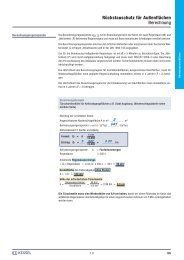
Technische Daten:<br />
Laufraddurchgang: max.10 mm<br />
Temperatur: kurzfristig max. 75°C<br />
im Dauerbetrieb max. 50°C<br />
bei tiefster Schwimmereinstellung<br />
Leistungsaufnahme<br />
Spannung Nennstrom<br />
P1 = 0,3 kW 230V~/50Hz 1,6 A<br />
Drehzahl Gewicht Kabellänge<br />
4.1 Anlagen - Daten:<br />
Leistungsdiagramm<br />
2800 U/min-1 10<br />
9<br />
8<br />
7<br />
6<br />
5<br />
4<br />
3<br />
2<br />
1<br />
7,3 kg 5 m<br />
0<br />
0 1 2 3 4 5 6 7 8 9 10<br />
Fördermenge Q (m³/h)<br />
Förderhöhe H (mWS)<br />
0 0,5 1 1,5 2 2,5<br />
Fördermenge Q (l/s)
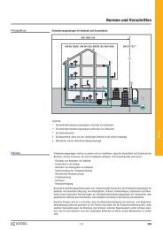
Inbetriebnahme, Inspektion/Wartung, Gewährleistung<br />
4.2 Hinweis<br />
- Die Installationen haben nach den geltenden<br />
Normen und Vorschriften zu erfolgen.<br />
- örtliche Vorschriften und Verordnungen sind<br />
zu beachten.<br />
- Die Druckrohrleitungen müssen über die<br />
örtlich festgelegten Rückstauebenen hochgeführt<br />
werden. Die Verbindungen der<br />
Druckleitung müssen längskraftschlüssig<br />
erfolgen.<br />
- Bevor die <strong>Minilift</strong> ® <strong>Hebeanlage</strong> in Betrieb<br />
genommen wird, muss fachmännisch überprüft<br />
werden, ob die Elektroinstallation den<br />
örtlichen EVU-Vorschriften entspricht. (EVU<br />
= Energie-Versorgungsunternehmer)<br />
- Die elektrische Steckvorrichtung ist vor Nässe<br />
zu schützen!<br />
5. Inspektion/Wartung<br />
5.1 Inspektion<br />
Die Anlage ist nach DIN EN 12056-4, monatlich<br />
vom Betreiber durch Inaugenscheinnahme<br />
auf Funktion und Dichtheit zu prüfen.<br />
5.2 Wartung<br />
Die Anlage ist nach DIN EN 12056-4 durch<br />
einen Fachkundigen zu warten:<br />
vierteljährlich bei Anlagen in gewerblichem<br />
Betrieb.<br />
halbjährlich bei Anlagen in Mehrfamilienhäusern.<br />
jährlich bei Anlagen in Einfamilienhäusern<br />
zusätzlich ist die Entlüftungsbohrung<br />
(siehe Kapitel 4) auf Verstopfung zu prüfen<br />
und ggf. zu reinigen.<br />
6. Gewährleistung<br />
1. Ist eine Lieferung oder Leistung mangelhaft,<br />
so hat <strong>KESSEL</strong> nach Ihrer Wahl den Mangel<br />
durch Nachbesserung zu beseitigen oder eine<br />
mangelfreie Sache zu liefern. Schlägt die<br />
Nachbesserung zweimal fehl oder ist sie wirtschaftlich<br />
nicht vertretbar, so hat der Käufer/Auftraggeber<br />
das Recht, vom Vertrag<br />
<strong>zur</strong>ückzutreten oder seine Zahlungspflicht<br />
entsprechend zu mindern. Die Feststellung<br />
von offensichtlichen Mängeln muss unverzüglich,<br />
bei nicht erkennbaren oder verdeckten<br />
Mängeln unverzüglich nach ihrer Erkennbarkeit<br />
schriftlich mitgeteilt werden. Für Nachbesserungen<br />
und Nachlieferungen haftet<br />
<strong>KESSEL</strong> in gleichem Umfang wie <strong>für</strong> den ursprünglichen<br />
Vertragsgegenstand. Für Neulieferungen<br />
beginnt die Gewährleistungsfrist<br />
neu zu laufen, jedoch nur im Umfang der<br />
11<br />
Neulieferung. Es wird nur <strong>für</strong> neu hergestellte<br />
Sachen eine Gewährleistung übernommen.<br />
Die Gewährleistungsfrist beträgt 24 Monate<br />
ab Auslieferung an unseren Vertragspartner.<br />
§ 377 HGB findet weiterhin Anwendung.<br />
<strong>Über</strong> die gesetzliche Regelung hinaus erhöht<br />
die <strong>KESSEL</strong> AG die Gewährleistungsfrist <strong>für</strong><br />
Leichtflüssigkeitsabscheider, Fettabscheider,<br />
Schächte, Kleinkläranlagen und Regenwasserzisternen<br />
auf 20 Jahre bezüglich Behälter.<br />
Dies bezieht sich auf die Dichtheit, Gebrauchstauglichkeit<br />
und statische Sicherheit.<br />
Voraussetzung hier<strong>für</strong> ist eine fachmännische<br />
Montage sowie ein bestimmungsgemäßer Betrieb<br />
entsprechend den aktuell gültigen Einbau-<br />
und Bedienungsanleitungen und den gültigen<br />
Normen.<br />
2. <strong>KESSEL</strong> stellt ausdrücklich klar, dass Verschleiß<br />
kein Mangel ist. Gleiches gilt <strong>für</strong><br />
Fehler, die aufgrund mangelhafter Wartung<br />
auftreten.<br />
Hinweis: Das Öffnen von versiegelten Komponenten<br />
oder Verschraubungen darf nur<br />
durch den Hersteller erfolgen. Andernfalls<br />
können Gewährleistungsansprüche ausgeschlossen<br />
sein.<br />
Stand 01. 06. 2010
❑ Rückstauverschlüsse<br />
❑ <strong>Hebeanlage</strong>n<br />
❑ Abläufe / Duschrinnen<br />
❑ Abscheider<br />
-Fettabscheider<br />
-Öl-/Benzin-/Koaleszenzabscheider<br />
-Stärkeabscheider<br />
-Sinkstoffabscheider<br />
❑ Kleinkläranlagen<br />
❑ Schächte<br />
❑ Regenwassernutzung
INSTALLATION AND OPERATING INSTRUCTIONS<br />
<strong>KESSEL</strong> - <strong>Minilift</strong> ® Greywater Pumping System<br />
For above or below ground installation<br />
Ill. 28 560<br />
Ill. 28 570<br />
The installation and service of this unit should be carried out<br />
by a licensed professional servicer<br />
Name/Sign Date Location Stamp company<br />
Art. nos. 28 560 / 28 570<br />
Product advantages<br />
Compact – easy installation<br />
Pumping height up to 6.5 meters (21 feet)<br />
Quick release mechanism for pump removal<br />
LGA<br />
Type-tested<br />
and monitored<br />
guaranteed with<br />
tested quality<br />
Approval no.: Z-53.3-387<br />
Edition: 06/2011<br />
ID number: 157-030<br />
Subject to technical amendments
Table of Contents<br />
1. General 1.1 Purpose ............................................................................................ Page 3<br />
1.2 Product description ........................................................................... Page 3<br />
1.2.1 Above floor / free standing installation .............................................. Page 3<br />
1.2.2 In the slab (below grade) installation ................................................ Page 3<br />
2. Applications 2.1 Permanent installations .................................................................... Page 4<br />
2.2 Removal of pump for use elsewhere ................................................ Page 4<br />
3. Installation 3.1 Installation in the slab (below grade) ................................................ Page 5/6<br />
3.2 Above floor / free standing installation .............................................. Page 7/8<br />
3.3 Tips ................................................................................................... Page 9<br />
4. Commissioning 4.1 Product information - data................................................................. Page 10<br />
4.2 Tips ................................................................................................... Page 11<br />
5. Inspection and maintenance 5.1 Inspection ......................................................................................... Page 11<br />
5.2 Maintenance ..................................................................................... Page 11<br />
6. Warranty .......................................................................................................... Page 11<br />
14
1.1 Application<br />
The <strong>Minilift</strong> ® is a wastewater lifting station<br />
designed for pumping sewage free wastewater<br />
(no WC connection) according to DIN<br />
EN 12056.<br />
1.2 Product description<br />
1.2.1.Above floor/free standing installation<br />
installed in a free standing / above grade<br />
area. The <strong>Minilift</strong> ® chamber is ventilated<br />
through an integrated activated charcoal filter<br />
which keeps any type of odor problems<br />
in the room of installation to a minimum. A<br />
separate (roof-exiting) ventilation pipe can<br />
be connected to the system if desired.<br />
The <strong>Minilift</strong> ® is an excellent choice for below<br />
grade renovations which include installations<br />
of showers, sinks, washing machines,<br />
etc. The newly installed fixtures can simply<br />
be plumbed into the <strong>Minilift</strong> ® which in turn<br />
will be connected to the existing buildingʼs<br />
wastewater piping (above the backwater<br />
level). Multiple inlets can be connected to<br />
the <strong>Minilift</strong> ® using the quickinstall <strong>KESSEL</strong><br />
inlet adaptors (Illustration 2).<br />
15<br />
1. General<br />
The pump is also equipped with a quickrelease<br />
lock (Illustration 1) for pump removal<br />
and use in other applications.<br />
1.2.2.In the slab (below grade) installation<br />
The <strong>Minilift</strong> ® for in the slab / below grade<br />
installations consists of a pumping chamber<br />
with cover and inlet grate. Multiple inlets can<br />
also be connected to the <strong>Minilift</strong> ® using the<br />
quick-install <strong>KESSEL</strong> inlet adaptors (Illustration<br />
2) and the pump can be removed using the<br />
quick-release lock (Illustration 1).<br />
Deeper installation depths can be accomodated<br />
by the use of a <strong>KESSEL</strong> variable height<br />
adjusting section which is available upon<br />
request. A separate ventilation pipe can be<br />
connected to the system if the inlet grate is<br />
removed and replaced with an available sealed<br />
cover.
2.1 Permanent installations<br />
- When the <strong>Minilift</strong> ® is permanently installed<br />
(as seen in the Illustration) it is important that<br />
only greywater is fed into the unit (showers,<br />
sinks, washing machines, etc.). Toilets, for<br />
example, are not to be plumbed into the <strong>Minilift</strong><br />
®.<br />
- The entire unit is of polymer construction for<br />
corrosion resistance. The <strong>Minilift</strong> ® pump is<br />
controlled by a float switch.<br />
- The <strong>Minilift</strong> ® is designed for connection to<br />
2. Applications<br />
standard household clothes washing machines.<br />
- The unit is delivered with a 5 meter (16.5 feet)<br />
power chord.<br />
- The <strong>Minilift</strong> ® can handle continuous wastewater<br />
at 50 C (122 deg F) and can handle up<br />
to 75 C (167 deg F) for short periods of time.<br />
2.2 Removal of pump for use elsewhere<br />
In cases that the <strong>Minilift</strong> ® pump is temporarily<br />
needed for another application, the pump can<br />
be quickly and easily removed by unlocking the<br />
quick-release lock. If removing the pump be<br />
sure not to remove the integrated backflow<br />
16<br />
flap. This flap assembly should remain attached<br />
to the Minilft chamber so that no wastewater<br />
in the outlet pressure pipe will flow back<br />
into the chamber. Also when removing the<br />
pump (if pump cable is run through an underground<br />
conduit) be sure to tie a string to the<br />
power chord plug so that the string will be pulled<br />
through the conduit and into the <strong>Minilift</strong> ®<br />
chamber. This will aid in guiding the plug back<br />
through the conduit and to the power source<br />
when re-installing the pump.<br />
TIP: By removing the black suction basket<br />
(#15) on the bottom of the pump, the suction<br />
height can be reduced. This can often be of<br />
help when the distance between the floor and<br />
the pumpʼs impeller needs to be as low as possible.<br />
Caution – before removing the black suction<br />
basket make sure the pump IS NOT connected<br />
to a power source.<br />
TIP: In cases where the pump is used to pump<br />
out swimming pools, small ponds or any area<br />
where people or animals may be present – be<br />
sure to follow all local and national electrical<br />
codes to ensure safety. This type of application<br />
must follow VDE 0100 Section 49d requirements.
3.1 Installation in the slab (below grade)<br />
Drainage points situated below public sewer level<br />
17<br />
3. Installation<br />
Before the <strong>Minilift</strong>® chamber is installed in the slab or floor area, the following must first be<br />
assembled (note all the (#) refer to the illustration on the following page):<br />
1. Place the flat gasket (#8) over the proper<br />
portion of the quick release mechanism<br />
(#6).<br />
2. Insert the interior rubber seal (#9) inside<br />
the other side of the quick release mechanism(#6).<br />
max. 45°<br />
3. Now insert the quick release mechanism<br />
from inside the <strong>Minilift</strong>® chamber through<br />
the pre-drilled hole so that it now sticks<br />
out of the exterior side of the chamber.<br />
4. From the exterior of the chamber, screw<br />
on the locking nut (#7) onto the threaded<br />
portion of the quick release mechanism<br />
which will securely fasten the entire fixt.<br />
5. Insert the <strong>Minilift</strong>® pump into the chamber<br />
and make sure that the base of the<br />
pump aligns and securely sits on the guiderails<br />
on the base of the chamber. Now<br />
move the pump forward so that the outlet<br />
of the pump (#4) securely inserts into the<br />
quick release mechanism (#6 & #9). Lock<br />
the pump in place by closing the locking<br />
lever (#5).<br />
CAUTION – Make sure that the pumpʼs<br />
power cable does not hinder the proper function<br />
/ movement of the pumpʼs float switch.<br />
6. Assemble the included DN 50 conduit adaptor<br />
into the pre-drilled hole (#13)<br />
7. If required, connect any additional inlets<br />
to the body of the <strong>Minilift</strong>® making sure<br />
that these inlets will not affect the function<br />
of the pumpʼs float switch.<br />
8. Place the chamber with pump into the<br />
prepared slab or floor opening. Connect<br />
the power cable conduit to the DN 50<br />
conduit adaptor. Connect all additional<br />
drainage pipe to the prepared inlets.
9. Making sure that these inlets will not affect<br />
the function of the pumpʼs float<br />
switch.<br />
10. Insert and glue the outgoing pressure<br />
pipe (DN 40) (according to DIN 8063) inside<br />
the outlet portion of the <strong>Minilift</strong> ® (#7<br />
& #6) (glue is supplied). Make sure that<br />
the outgoing pressure pipe is securely<br />
installed.<br />
CAUTION – Before pouring concrete, make<br />
sure to protect the solid cover (#2) and grated<br />
cover (#11) with a foil or plastic wrap so<br />
that these pieces stay clean.<br />
11. After all conduit and drainage pipe<br />
connections have been properly made<br />
pour concrete around <strong>Minilift</strong> ® and secure<br />
in place.<br />
11. If deeper installations are necessary,<br />
<strong>KESSEL</strong> extension section (Article<br />
#32500) can be used. Seal between the<br />
extension section and the <strong>Minilift</strong> ®<br />
chamber must be made with a standard<br />
flexible silicon caulk.<br />
3. Installation<br />
1. Chamber<br />
2. Cover and grate<br />
3. Pump<br />
4. Pump outlet<br />
5. Locking lever<br />
6. Quick release mechanism<br />
7. Locking nut<br />
8. Flat gasket<br />
9. Rubber seal<br />
10. O-ring<br />
11. Grated cover<br />
12. Pump power cable<br />
13. DN 50 hole<br />
14. Float switch<br />
15. Suction basket<br />
16. Float switch adjustment<br />
17. Back flow flap<br />
18
3.2 Above floor / free standing installation<br />
Drainage points situated below public sewer level<br />
19<br />
3. Installation<br />
Before installing the <strong>Minilift</strong> please make<br />
sure that the following steps are taken:<br />
1. Place the flat gasket (#8) over the proper<br />
portion of the quick release mechanism<br />
(#6).<br />
2. Insert the interior rubber seal (#9) inside<br />
the other side of the quick release mechanism<br />
(#6).<br />
3. Now insert the quick release mechanism<br />
from inside the <strong>Minilift</strong> ® chamber through<br />
the pre- drilled hole so that it now sticks<br />
out of the exterior side of the chamber.<br />
4. From the exterior of the chamber, screw<br />
on the locking nut (#7) onto the threaded<br />
portion of the quick release mechanism<br />
which will securely fasten the entire fixture.<br />
5. Insert the <strong>Minilift</strong> ® pump into the chamber<br />
and make sure that the base of the pump<br />
aligns and securely sits on the guiderails<br />
on the base of the chamber. Now move<br />
the pump forward so that the outlet of the<br />
pump (#4) securely inserts into the quick<br />
release mechanism (#6 & #9). Lock the
pump in place by closing the locking lever<br />
(#5).<br />
CAUTION – Make sure that the pumpʼs<br />
power cable does not hinder the proper function<br />
/ movement of the pumpʼs float switch.<br />
6. If required, connect any additional inlets<br />
to the body of the <strong>Minilift</strong> ® making sure<br />
that these inlets will not affect the function<br />
of the pumpʼs float switch.<br />
7. Insert and glue the outgoing pressure<br />
pipe (DN 40)(according to DIN 8063) inside<br />
the outlet portion of the <strong>Minilift</strong> ® (#7 &<br />
#6) (glue is supplied). Make sure that the<br />
outgoing pressure pipe is securely installed.<br />
8. The <strong>Minilift</strong> ® (art.no. 28560) is ventilated<br />
through the charcoal filter located on the<br />
<strong>Minilift</strong> ® cover. If desired, a separate ventilation<br />
pipe can also be run to the buildingʼs<br />
main ventilation pipe or directly to<br />
the roof.<br />
3. Installation<br />
1. Chamber<br />
2. Chamber cover<br />
3. Pump<br />
4. Pump outlet<br />
5. Locking lever<br />
6. Outlet connection.<br />
7. Locking nut<br />
8. Flat gasket<br />
9. Rubber seal<br />
10. Quick release mechanism<br />
11. Power cable seal (interior)<br />
12. Power cable seal (exterior)<br />
13. Cable port seal<br />
14. Fastening screw<br />
15. Activated charcoal filter<br />
16. Securing spring<br />
17. Rubber seal<br />
18. Cover gasket<br />
19. Rubber cushions<br />
20. Pump power chord<br />
21. Suction basket<br />
22. Float switch<br />
23. Cover fastening screws<br />
24. Cover fastening bolts<br />
20
3.3 Additional inlets<br />
Connection of lateral inlets or cable conduits<br />
(for concrete floor installation) size<br />
DN 50.<br />
Additional inlets can be connected to the<br />
chamber of the <strong>Minilift</strong> ® by cutting out precision<br />
DN 50 holes with the <strong>KESSEL</strong> drill<br />
attachment (Order # 50100). Please make<br />
sure that any additional inlets connected to<br />
the <strong>Minilift</strong> ® chamber do not interere with the<br />
functioning of the pumpʼs float switch. Please<br />
note that a minimum height of 60 mm<br />
should be maintained between the inlet<br />
level of all pipes and the bottom of the<br />
chamber.<br />
21<br />
3. Installation<br />
Please note: The float switch operation/<br />
movement should not be blocked by any<br />
additional lateral inlet (DN 50).<br />
Illustration of hole drilling and inlet connection for additional lateral<br />
inlet (DN 50).
4. Commissioning:<br />
Commissioning the <strong>Minilift</strong> ® takes place<br />
simply by plugging in the pumpʼs power<br />
chord after all installation procedures have<br />
been properly completed as stated in this<br />
manual. It is, however, important that the<br />
float switch is inspected to make sure that it<br />
has free movement and does not risk becoming<br />
jammed or tangled with an inlet pipe or<br />
the pumpʼs power chord.<br />
The float switch can be adjusted in order to<br />
specify the wastewater height which will<br />
cause the pump to turn on. For decreasing<br />
the wastewater height which will cause the<br />
pump to activate, unscrew the float switch<br />
cable attachment as seen in the diagram<br />
and shorten the distance between the cable<br />
fastening clamp and the float switch. To increase<br />
the wastewater height which will<br />
cause the pump to activate, lengthen the distance<br />
between the cable fastening clamp<br />
and the float switch.<br />
4. Commissioning<br />
Attention:<br />
If a low level lateral inlet has been added to<br />
the <strong>Minilift</strong> (inlet should be at least 60mm<br />
higher than the interior base of the Minilist)<br />
and it is desired to lower the wastewater activation<br />
level of the pump, the float switch<br />
cable should be connected to the lowest<br />
bracket (low suction height bracket). The<br />
length of the float switch should not be<br />
changed and should remain at the factory<br />
set 180 +/- 5mm length (measured from securing<br />
bracket to end of float switch).<br />
ventilation<br />
hole<br />
low height suction<br />
22<br />
4.1 Product information – data<br />
Power curve<br />
Förderhöhe H (mWS)<br />
Pumping height H (mWS)<br />
10<br />
9<br />
8<br />
7<br />
6<br />
5<br />
4<br />
3<br />
2<br />
1<br />
0<br />
0 1 2 3 4 5 6 7 8 9 10<br />
Pumping Fördermenge capacity Q (m³/h) Q (m3/h) 0 0,5 1 1,5 2 2,5<br />
Fördermenge Pumping capacity Q (l/s) Q<br />
Technical Information:<br />
Free passage thru impeller – max. 10 mm<br />
Continuous wastewater pumping at 50° C<br />
(122° F)<br />
Short term wastewater pumping at 75° C<br />
(167° F)<br />
Power Voltage Current<br />
P1 = 0,3 kW 230V~/50Hz 1,6 A<br />
Revolutions Weight cable length<br />
2800 U/min -1 7,3 kg 5 m
Commissioning, Inspection and Maintenance, Warranty<br />
4.2 Tips<br />
- Installation should meet the requirement of<br />
all local and national codes and standards.<br />
- The oultlet pressure pipe of the <strong>Minilift</strong>®<br />
should be plumbed above the locally defined<br />
backwater level and then into the buildingʼs<br />
main wastewater line.<br />
- Before the <strong>Minilift</strong> ® is placed into operation<br />
it should be inspected to certify that it is in<br />
compliance with all local and national electrical<br />
codes and standards.<br />
- The plug of the <strong>Minilift</strong> ® power chord (when<br />
plugged in or not) should be protected from<br />
moisture, water or any other fluid!<br />
- The <strong>Minilift</strong> ® must not be used to pump corrosive,<br />
flammable or explosive fluids!<br />
5. Inspection and Maintenance<br />
5.1 Inspection<br />
According to DIN 1986, Part 31, the <strong>Minilift</strong> ®<br />
unit is to be visually inspected for proper function<br />
and watertightness on a monthly basis.<br />
5.2 Maintenance<br />
According to DIN 1986, Pat 31, the <strong>Minilift</strong> ®<br />
unit is to be maintained by a trained<br />
tradesman at the following intervals:<br />
<strong>Minilift</strong>® units installed in commerical<br />
areas should be maintained on a quarterly<br />
basis.<br />
<strong>Minilift</strong>® units installed in multiple family<br />
homes or apartment buildings should be<br />
maintained on a semi-annual basis.<br />
<strong>Minilift</strong>® units installed in single family<br />
homes should be maintained on an annual<br />
basis.<br />
6. Warranty<br />
1. In the case that a <strong>KESSEL</strong> product is defective,<br />
<strong>KESSEL</strong> has the option of repairing or replacing<br />
the product. If the product remains defective<br />
after the second attempt to repair or replace<br />
the product or it is economically unfeasible<br />
to repair or replace the product, the<br />
customer has the right to cancel the order /<br />
contract or reduce payment accordingly. KES-<br />
SEL must be notified immediately in writing of<br />
defects in a product. In the case that the defect<br />
is not visible or difficult to detect, <strong>KESSEL</strong> must<br />
be notified immediately in writing of the defect<br />
as soon as it is discovered. If the product is repaired<br />
or replaced, the newly repaired or replaced<br />
product shall receive a new warranty<br />
identical to that which the original (defective)<br />
product was granted. The term defective product<br />
refers only to the product or part needing<br />
23<br />
repair or replacement and not necessarily to<br />
the entire product or unit. <strong>KESSEL</strong> products<br />
are warranted for a period of 24 month. This<br />
warranty period begins on the day the product<br />
is shipped form <strong>KESSEL</strong> to its customer. The<br />
warranty only applies to newly manufactured<br />
products. Additional information can be found<br />
in section 377 of the HGB.<br />
In addition to the standard warranty, <strong>KESSEL</strong><br />
offers an additional 20 year warranty on the<br />
polymer bodies of class I / II fuel separators,<br />
grease separators, inspection chambers, wastewater<br />
treatment systems and rainwater storage<br />
tanks. This additional warranty applies to<br />
the watertightness, usability and structural<br />
soundness of the product.<br />
A requirement of this additional warranty is that<br />
the product is properly installed and operated<br />
in accordance with the valid installation and<br />
user's manual as well as the corresponding<br />
norms / regulations.<br />
2. Wear and tear on a product will not be considered<br />
a defect. Problems with products resulting<br />
from improper installation, handling or<br />
maintenance will also not be considered a defect.<br />
Note: Only the manufacturer may open<br />
sealed components or screw connections.<br />
Otherwise, the warranty may become null and<br />
void. 01.06.2010
❑ Backwater protection<br />
❑ Lifting Stations and pumps<br />
❑ Drains and shower channels<br />
❑ Separators<br />
-Grease Separators<br />
-Oil-/Fuel-/Coalescence Separators<br />
-Starch Separators<br />
-SedimentSeparators<br />
❑ Septic Systems<br />
❑ Inspection Chambers<br />
❑ Rainwater Management Systems